3. Development Tutorial (Arduino)
After the program is successfully downloaded, the robot chassis will execute the movements in the following predefined sequence:
(1) Move Forward
(2) Move Backward
(3) Move Left or Right (Lateral Movement)
(4) Turn Left or Right in Place
(5) Move Left-Forward and Right-Backward (Diagonal Movement)
(6) Drift Left or Right in Place
Each action will be executed for 2 seconds.
There will be a 1-second interval between the execution of different actions.
3.1 Arduino Installation & Wiring
(1) Hardware Required for Arduino Development
(2) Motor Driver Installation
(3) Arduino Installation
(4) Wring
(5) Battery Installation & Wiring
3.2 Hardware Introduction
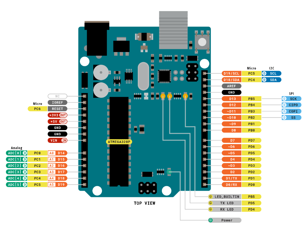
3.2.1 Arduino Uno
The Arduino Uno is a versatile and beginner-friendly open-source electronics prototyping platform. It features 14 digital input/output pins (6 of which can be used as PWM outputs), 6 analog input pins, a 16 MHz ceramic resonator (CSTCE16M0V53-R0), a USB connection, a power jack, an ICSP header, and a reset button.
Below is a schematic diagram of the Arduino Uno physical pins (please refer to your specific Arduino Uno board for accurate pinout details):
3.2.2 4-Channel Motor Driver
This motor driver module is designed to work with a microcontroller to drive TT motors or magnetic encoder motors. Each channel is equipped with a motor driver chip (YX-4055AM), with an operating voltage range of DC 3V-12V. The specific voltage should match the motor being connected. The pin layout is shown in the diagram below:
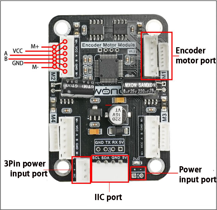
Interface Pin Description
| Encoder Motor Interface | GND | Hall power negative |
|---|---|---|
| A | Phase A pulse signal output | |
| B | Phase B pulse signal output | |
| VCC | Hall power positive | |
| M+ | Motor power positive | |
| M- | Motor power negative | |
| Note:The voltage between `VCC` and `GND` is determined by the power supply voltage of the microcontroller, typically 3.3V or 5V. When the motor shaft rotates clockwise, the A channel pulse signal precedes the B channel signal. When the shaft rotates counterclockwise, the A channel signal follows the B channel. The voltage between `M+` and `M-` depends on the motor voltage. |
||
| IIC | SCL | Clock line |
| SDA | Bidirectional data line | |
| GND | Ground | |
| 5V | 5V DC output | |
| 3Pin power interface | - | Power negative input |
| + | Power positive input | |
| NC | Not connected | |
| Power interface | + | Power positive input |
| - | Power negative | |
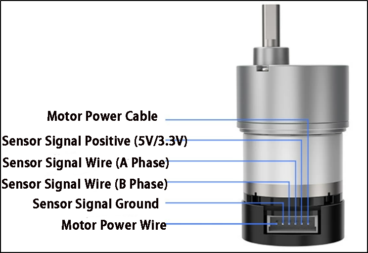
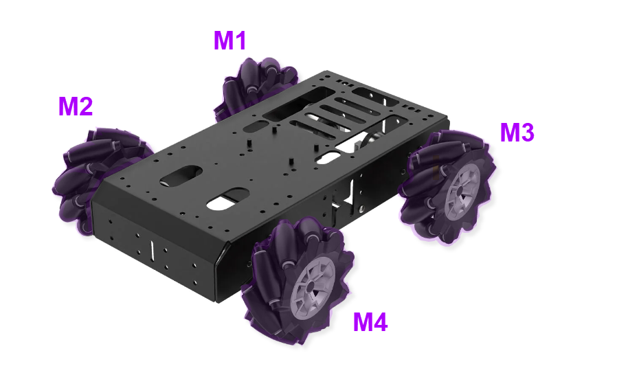
3.2.3 Encoder Reduction Motor
The chassis is equipped with a motor model JGB37-528R131-08. The designation details are as follows:
(1) J: DC motor
(2) GB: Offset output shaft
(3) 37: Gearbox diameter (mm)
(4) 528: Motor model number
(5) R131: Reduction ratio of 131:1
(6) 08: Rated voltage of 8V
The interface details are shown in the diagram below:
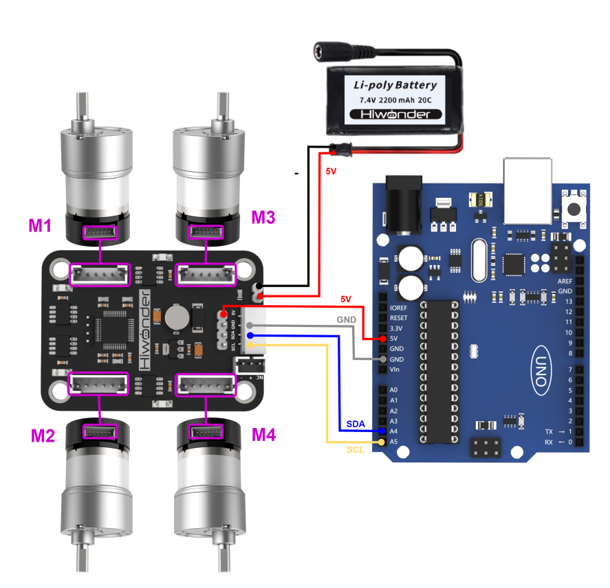
3.3 Wiring Instructions
Arduino Uno with 4-Channel Encoder Motor Driver Module, powered by a 7.4V 2200mAh lithium battery to drive the motors. The following is the general wiring diagram for Arduino Uno control:
3.4 Environment Configuration and Program Download
3.4.1 Environment Configuration
Prior to downloading, ensure that the Arduino IDE is installed on your computer. You can find the software package in the Appendix->Arduino Installation Package.
3.4.2 Program Running
Open the “car_move_demo.ino” program saved in Appendix->car_move_demo using Arduino IDE.
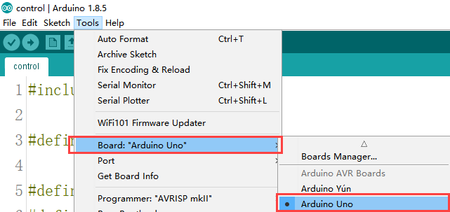
(1) Choose the Arduino development board type. In this case, select “Arduino UNO”
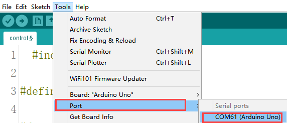
(2) Select the USB port the Arduino currently connecting to your computer. The IDE will detect it automatically; in this case, choose “COM61”.
(3) Connect Arduino UNO to the computer. Select “Arduino UNO” in the tool bar, and click-on  to download the program.
(4) The software will compile the program automatically. Please wait until the compilation process is successfully completed.
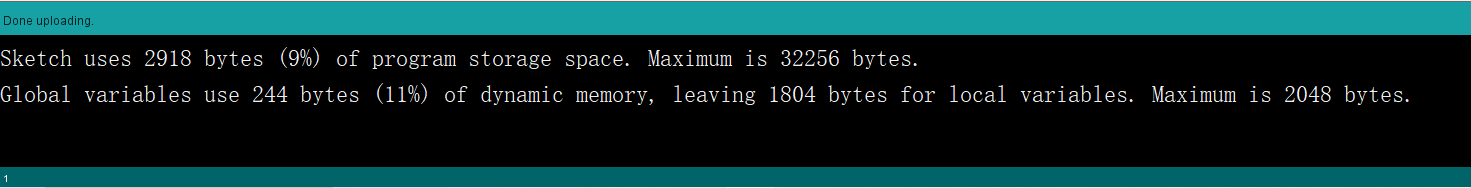
(5) Wait for the program to finish uploading.
3.4.3 Program Outcome
After downloading the program, the robot chassis will execute actions in the following predetermined order:
(1) Move forward
(2) Move backward
(3) Move left
(4) Move right
(4) Turn left
(5) Move backward left
(6) Turn right
(7) Move backward right
(8) Rotate left in place
(9) Rotate right in place
Each action will run for 2 seconds, with a 1-second interval between each action.
3.5 Sample Program Brief Analysis
Import Necessary Libraries
The required packages are built into the Arduino IDE. Go to “Project -> Load Libraries” to add them. These libraries contain methods for IIC communication, which are used to control the rotation of motors.
1 | #include <Wire.h>
|
Initialize Communication Address
Define macros for the IIC communication address and the addresses of various motor types to make future calls easier. The default IIC communication address for the driver board is 0x34, which can be left as default based on your hardware. Set the encoder motor type address MOTOR_TYPE_ADDR to 20. These numbers represent the address locations for writing parameters, not the actual parameter values, which depend on your hardware. Keep the defaults for now. For motor control, the address MOTOR_FIXED_SPEED_ADDR is set to 51, which is the address for speed control of the four encoder motors. If speed control for the chassis motors is needed in future, you can change this address during IIC interface writes, but for now, keep it as default.
3 4 5 6 7 8 9 10 11 12 13 14 15 16 17 18 19 20 21 | #define I2C_ADDR 0x34 #define ADC_BAT_ADDR 0 #define MOTOR_TYPE_ADDR 20 // Encoder motor type setting #define MOTOR_ENCODER_POLARITY_ADDR 21 // Set encoder direction polarity // If you find the motor speed is completely uncontrollable (either running at max speed or stopped), // you may need to reconfigure the value at this address // Range: 0 or 1, default is 0 #define MOTOR_FIXED_PWM_ADDR 31 // Fixed PWM control (open-loop control), range (-100~100) //#define SERVOS_ADDR_CMD 40 #define MOTOR_FIXED_SPEED_ADDR 51 // Fixed speed control (closed-loop control), // Unit: pulses per 10ms. Range depends on specific encoder motor (affected by encoder line count, // voltage, load, etc.), typically around ±50 #define MOTOR_ENCODER_TOTAL_ADDR 60 // Total pulse count for each of the 4 encoder motors // If the pulses per revolution (U) is known and wheel diameter (D) is known, // the travel distance can be calculated from pulse count: // For example, if motor 1's total pulse count is P, then travel distance = (P/U) * (3.14159*D) // For different motors, you can manually test U by rotating 10 turns and taking the average pulse count |
(2) Initialize Motor Type
The four-channel driver module supports various types of motors, including TTL, N20, and JGB motors. All motor types are defined as macros. In this development, we are using JGB motors, so the motor type macro is set to 3.
21 22 23 24 25 | // Motor type specific values #define MOTOR_TYPE_WITHOUT_ENCODER 0 #define MOTOR_TYPE_TT 1 #define MOTOR_TYPE_N20 2 #define MOTOR_TYPE_JGB 3 // Magnetic encoder (44 pulses per revolution), gear ratio: 131 (default) |
Motor and Control Setup
The lines MotorType = MOTOR_TYPE_JGB and MotorEncoderPolarity = 0 define the motor type and encoder polarity.
① MOTOR_TYPE_JGB is a predefined constant representing the JGB motor model.
② MotorEncoderPolarity = 0 sets the encoder polarity to the default configuration.
③ Wire.begin() starts the IIC bus communication and initializes it with this function.
④ The functions WireWriteDataArray(MOTOR_TYPE_ADDR, &MotorType, 1) and WireWriteDataArray(MOTOR_ENCODER_POLARITY_ADDR, &MotorEncoderPolarity, 1) send the motor type and encoder polarity to the specified addresses via the IIC protocol.
88 89 90 91 92 93 94 95 96 97 98 99 100 | uint8_t MotorType = MOTOR_TYPE_JGB; uint8_t MotorEncoderPolarity = 0; void setup() { Wire.begin(); delay(200); WireWriteDataArray(MOTOR_TYPE_ADDR,&MotorType,1); delay(5); WireWriteDataArray(MOTOR_ENCODER_POLARITY_ADDR,&MotorEncoderPolarity,1); delay(2000); } |
Movement Action Setup
In the code, various motion types are set, including the initial motor speed for each action. For example, car_forward[4] = {30, -30, -30, 30} defines the motor speeds for M1, M2, M3, and M4. Since the motors may be mounted in reverse, the initial direction for forward motion must be configured. The speed range is recommended to be [-50, 50].
102 103 104 105 106 107 108 109 110 111 112 113 114 115 116 117 118 119 120 121 122 123 124 125 126 | int8_t car_forward[4] = {30, -30, -30, 30}; // Forward movement int8_t car_back[4] = {-30, 30, 30, -30}; // Backward movement int8_t car_left_transform[4] = {-30, -30, -30, -30}; // Left strafe (sideways) int8_t car_right_transform[4] = {30, 30, 30, 30}; // Right strafe (sideways) int8_t car_turn_left[4] = {30, -30, -10, 10}; // Pivot turn left (forward arc) int8_t car_turn_right[4] = {10, -10, -30, 30}; // Pivot turn right (forward arc) int8_t car_turn_left_back[4] = {-30, 30, 10, -10}; // Reverse pivot turn left int8_t car_turn_right_back[4] = {-10, 10, 30, -30}; // Reverse pivot turn right int8_t car_turn_right_orin[4] = {-30, 30, -30, 30}; // In-place clockwise rotation int8_t car_turn_left_orin[4] = {30, -30, 30, -30}; // In-place counter-clockwise rotation int8_t car_Ob_translation_left_up[4] = {0, -30, -30, 0}; // Diagonal front-left movement int8_t car_Ob_translation_right_up[4] = {30, 0, 0, 30}; // Diagonal front-right movement int8_t car_Ob_translation_left_back[4] = {-30, 0, 0, -30}; // Diagonal rear-left movement int8_t car_Ob_translation_right_back[4] = {0, 30, 30, 0}; // Diagonal rear-right movement int8_t car_drift_left[4] = {-30, 0, -30, 0}; // Left drift int8_t car_drift_right[4] = {30, 0, 30, 0}; // Right drift int8_t car_stop[4] = {0, 0, 0, 0}; // Full stop |
Chassis Movement Execution Function
The Running function is used to execute the chassis movement. The running_mode[4] array stores the movement mode parameters, which correspond to previously defined actions. The WireWriteDataArray(MOTOR_FIXED_SPEED_ADDR, running_mode, 4) function writes the current motor speeds to control movement. After a delay of 2000 milliseconds (delay(2000)), the stop action car_stop is executed, with a duration of 1 second.
130 131 132 133 134 135 136 | void Running(int8_t running_mode[4]) { WireWriteDataArray(MOTOR_FIXED_SPEED_ADDR,running_mode,4); //Perform the corresponding action. delay(2000); WireWriteDataArray(MOTOR_FIXED_SPEED_ADDR,car_stop,4); // stop delay(1000); } |
Main Function
In the main function, the previously written Running function is called with the corresponding action parameters, resulting in different motion effects. The functions execute in sequence, and by changing the parameters passed to the action functions, different movement sequences can be achieved.
138 139 140 141 142 143 144 145 146 147 148 149 150 151 152 153 | void loop() { // Execute various movement patterns sequentially Running(car_forward); // Move forward Running(car_back); // Move backward Running(car_left_transform); // Strafe left Running(car_right_transform); // Strafe right Running(car_turn_left_orin); // Rotate left in place Running(car_turn_right_orin); // Rotate right in place Running(car_Ob_translation_left_up); // Diagonal front-left movement Running(car_Ob_translation_right_back); // Diagonal rear-right movement Running(car_drift_left); // Left drift maneuver Running(car_drift_right); // Right drift maneuver while(1){} // Infinite loop (halt execution after completing sequence) } |
3.6 Development Notes
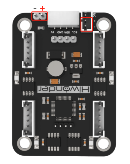
(1) The rated working voltage for the Arduino Uno is 5V, with an input voltage range of 7-12V. However, the IIC interface of the four-motor encoder driver module cannot be used directly to power the Arduino Uno, as the 5V on IIC only supports voltage input and not output. Since the Mecanum wheels do not have additional sensors or components, the 5V output from the IIC serial interface of the four-motor encoder driver module can be used to power the Arduino Uno.
(2) When developing independently, it is recommended not to directly connect the positive and negative power terminals of the four-motor encoder driver module to the main controller’s power supply terminals if no electrical protection circuit is available. This is to prevent damage to the main controller’s resistors, capacitors, or the main controller chip. The position is shown in the red box in the diagram below: