2. Bus Servo Controller Secondary Development
2.1 Bus Servo Controller Communication Protocol
Serial communication, baud rate: 9600
Command packet data type: Hexadecimal
Command Packet Format:
| Frame Header | Data Length | Command | Parameters |
|---|---|---|---|
| 0x55 0x55 | Length | Cmd | Prm 1…Prm N |
Frame Header: Two consecutive 0x55 bytes indicate the start of a data packet.
Data Length: The total length of the packet, calculated as the number of parameters (N) plus 2 bytes, 1 byte for the command and 1 byte for the length itself. The data length formula is Length = N + 2.
Command: Various control commands.
Parameters: Additional control information required by the command.
2.1.1 User-Initiated Data Transmission to the Controller
The user’s transmission data pin should be connected to the controller’s RX pin. Additionally, the user’s control system must share a common ground (GND) with the controller. If the data sent is incorrect, the blue LED2 will remain steadily lit without blinking, and the buzzer will sound twice (“beep beep”) to alert the user of the data transmission error.
(1) Command Name: CMD_SERVO_MOVE
Description: Controls the movement of any number of servos.
| Frame Header | Data Length | Command | Parameters |
|---|---|---|---|
| 0x55 0x55 | Number of servos * 3 + 5 | 3 | Prm 1…Prm N |
Parameter 1: Number of servos to control
Parameter 2: Time low byte
Parameter 3: Time high byte
Parameter 4: Servo ID
Parameter 5: Angle position low byte
Parameter 6: Angle position high byte
Subsequent parameters: Same format as parameters 4, 5, and 6, for controlling additional servos’ positions. Example:
① Control servo 1 to move to position 800 within 1000 ms:
| 0x55 0x55 | 0x08 | 0x03 | 0x01 0xE8 0x03 0x01 0x20 0x03 |
|---|---|---|---|
② Control servos 2 and 9 to move to position 800 within 800 ms:
| 0x55 0x55 | 0x0B | 0x03 | 0x02 0x20 0x03 0x02 0x20 0x03 0x09 0x20 0x03 |
|---|---|---|---|
(2) Command Name: CMD_ACTION_GROUP_RUN
Description: Controls the execution of an action group. Note that the action group must already be downloaded to the controller. You can set the number of times the action group runs. If you want it to run continuously, set the repeat count parameter to 0, which means infinite loops.
| Frame Header | Data Length | Command | Parameters |
|---|---|---|---|
| 0x55 0x55 | 5 | 6 | Prm 1 Prm 2 Prm 3 |
Parameter 1: The ID number of the action group to run.
Parameter 2: Lower 8 bits of the repeat count.
Parameter 3: Upper 8 bits of the repeat count.
Examples:
① Run action group 8 once:
| 0x55 0x55 | 0x05 | 0x06 | 0x08 0x01 0x00 |
|---|---|---|---|
② Run action group 2 infinitely:
| 0x55 0x55 | 0x05 | 0x06 | 0x02 0x00 0x00 |
|---|---|---|---|
(3) Command name: CMD_ACTION_GROUP_STOP
Description: Stop the currently running action group. If no action group is running, sending this command has no effect.
| Frame Header | Data Length | Command | Parameters |
|---|---|---|---|
| 0x55 0x55 | 2 | 7 | None |
Examples:
Stop the currently running action group:
| 0x55 0x55 | 0x02 | 0x07 |
|---|---|---|
(4) Command name: CMD_ACTION_GROUP_SPEED
Description: Controls the speed of the action group, expressed as a percentage. For example, to set the speed of action group 1 to twice the original speed, set the percentage value to 200, meaning 200%. If the action group number is 0xFF, it means adjusting the speed of all downloaded action groups.
Note
The adjusted speed parameter is not saved after power-off. Each time the device is powered on, the action groups will run at the default speed. If you need to adjust the speed, you must resend this command.
Servos have their own maximum speed limits. If the set speed exceeds the servo’s maximum speed, the adjustment will not take effect.
| Frame Header | Data Length | Command | Parameters |
|---|---|---|---|
| 0x55 0x55 | 5 | 11 | Prm 1 Prm 2 Prm 3 |
Parameter 1: Action group number to be adjusted
Parameter 2: Lower 8 bits of the speed percentage
Parameter 3: Higher 8 bits of the speed percentage
Examples:
① To set action group 8 to run at 50% speed:
| 0x55 0x55 | 0x05 | 0x0B | 0x08 0x32 0x00 |
|---|---|---|---|
② To set all downloaded action groups to run at 300% speed (3× original speed):
| 0x55 0x55 | 0x05 | 0x0B | 0xFF 0x2C 0x01 |
|---|---|---|---|
(5) Command name: CMD_GET_BATTERY_VOLTAGE
Description: Get the battery voltage of the controller, in millivolts (mV). After this command is sent, the controller will immediately return a data packet containing two parameters.
| Frame Header | Data Length | Command | Parameters |
|---|---|---|---|
| 0x55 0x55 | 2 | 15 | None |
Returned data packet from the controller:
| Frame Header | Data Length | Command | Parameters |
|---|---|---|---|
| 0x55 0x55 | 4 | 15 | Prm 1 Prm 2 |
Parameter 1: Lower 8 bits of the voltage value
Parameter 2: Higher 8 bits of the voltage value
Example: Get the controller’s battery voltage:
| 0x55 0x55 | 0x02 | 0x0F |
|---|---|---|
If the returned voltage value is 7500 mV:
| 0x55 0x55 | 0x04 | 0x0F | 0x4C 0x1D |
|---|---|---|---|
(6) Command name: CMD_MULT_SERVO_UNLOAD
Description: Used to power off multiple servos. Once this command is sent, the specified servos will lose holding torque and can be freely rotated by hand.
| Frame Header | Data Length | Command | Parameters |
|---|---|---|---|
| 0x55 0x55 | Number of servos to control + 3 | 20 | Prm 1…Prm N |
Parameter 1: Number of servos to control
Parameter 2: ID of servo a
Parameter 3: ID of servo b
Parameter …: ID of servo x
Example:
① Unload servos with IDs 1, 2, and 3.
| 0x55 0x55 | 0x06 | 0x14 | 0x03 0x01 0x02 0x03 |
|---|---|---|---|
② Unload servos with IDs 1, 2, 3, 4, 5, and 6.
| 0x55 0x55 | 0x09 | 0x14 | 0x06 0x01 0x02 0x03 0x04 0x05 0x06 |
|---|---|---|---|
(7) Command name: CMD_MULT_SERVO_POS_READ
Description: Reads the angle position values of multiple servos.
| Frame Header | Data Length | Command | Parameters |
|---|---|---|---|
| 0x55 0x55 | Number of servos to control + 3 | 21 | Prm 1…Prm N |
Parameter 1: Number of servos to read
Parameter 2: ID of servo a
Parameter 3: ID of servo b
Returned data packet from the controller:
| Frame Header | Data Length | Command | Parameters |
|---|---|---|---|
| 0x55 0x55 | Number of servos to read*3 + 3 | 21 | Prm 1…Prm N |
Parameter 1: Number of servos to read
Parameter 2: Servo ID
Parameter 3: Angle position low byte
Parameter 4: Angle position high byte
Parameters …: The format is the same as Parameters 2, 3, and 4, and is used to read the angle position of different servo IDs.
Examples:
Read the angle positions of servos with IDs 1, 2, 3, 4, 5, and 6:
| 0x55 0x55 | 0x09 | 0x15 | 0x06 0x01 0x02 0x03 0x04 0x05 0x06 |
|---|---|---|---|
For example, if all returned angle position values are 500:
| 0x55 0x55 | 0x15 | 0x15 | 0x06 0x01 0xF4 0x01 0x02 0xF4 0x01 0x03 0xF4 0x01 0x04 0xF4 0x01 0x05 0xF4 0x01 0x06 0xF4 0x01 |
|---|---|---|---|
2.1.2 Data Sent by the Controller
During operation, when the controller’s status changes, it will actively send data to the user via the serial port. For example, when an action group finishes running. There are multiple ways to operate the controller, such as using a PS2 controller, connecting via a Bluetooth module, or using the user’s custom serial interface. Hence, it is necessary for different control methods to be aware of the current status of the controller to facilitate proper management and operation. The following are the instructions that the controller returns to the user.
(1) Command name: CMD_ACTION_GROUP_RUN
Description: When the user sends a data packet to start running an action group, at the moment the action group starts running, the controller returns a data packet. The data format is exactly the same as the data packet sent by the user.
| Frame Header | Data Length | Command | Parameters |
|---|---|---|---|
| 0x55 0x55 | 5 | 6 | Prm 1 Prm 2 Prm 3 |
Parameter 1: The action group ID to be run.
Parameter 2: Low byte of the number of times to run the action group.
Parameter 3: High byte of the number of times to run the action group.
Example:
When action group 8 is running and is set to run once, the controller returns the following data packet to the user:
| 0x55 0x55 | 0x05 | 0x06 | 0x08 0x01 0x00 |
|---|---|---|---|
(2) Command name: CMD_ACTION_GROUP_STOP
Description: When a running action group is forcibly stopped by another method, for example, via the gamepad or by the user sending a stop command, this command is returned. The data packet format is the same as the one sent by the user when actively sending a stop command.
| Frame Header | Data Length | Command | Parameters |
|---|---|---|---|
| 0x55 0x55 | 2 | 7 | None |
Examples:
When an action group that is currently running is forcibly stopped, the following data is returned:
| 0x55 0x55 | 0x02 | 0x07 |
|---|---|---|
(3) Command name: CMD_ACTION_GROUP_COMPLETE
Description: When an action group finishes running naturally, not forcibly stopped, but completes on its own, this command is returned.
| Frame Header | Data Length | Command | Parameters |
|---|---|---|---|
| 0x55 0x55 | 5 | 8 | Prm 1 Prm 2 Prm 3 |
Parameter 1: The action group ID to be run.
Parameter 2: Low byte of the number of times to run the action group.
Parameter 3: High byte of the number of times to run the action group.
Example:
When action group No. 8 is set to run once and finishes naturally, the controller returns the following data to the user:
| 0x55 0x55 | 0x05 | 0x08 | 0x08 0x01 0x00 |
|---|---|---|---|
2.2 Arduino Development
2.2.1 Getting Started
Wiring Instruction
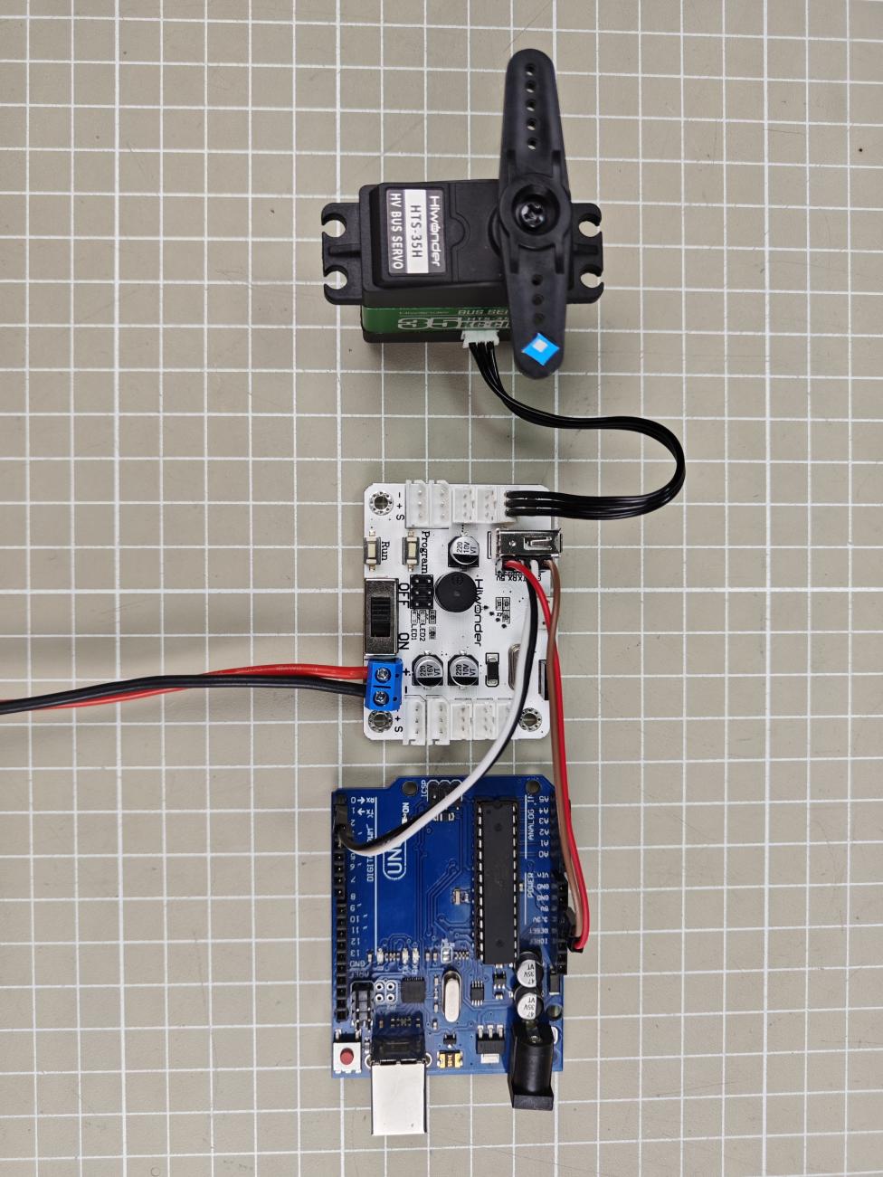
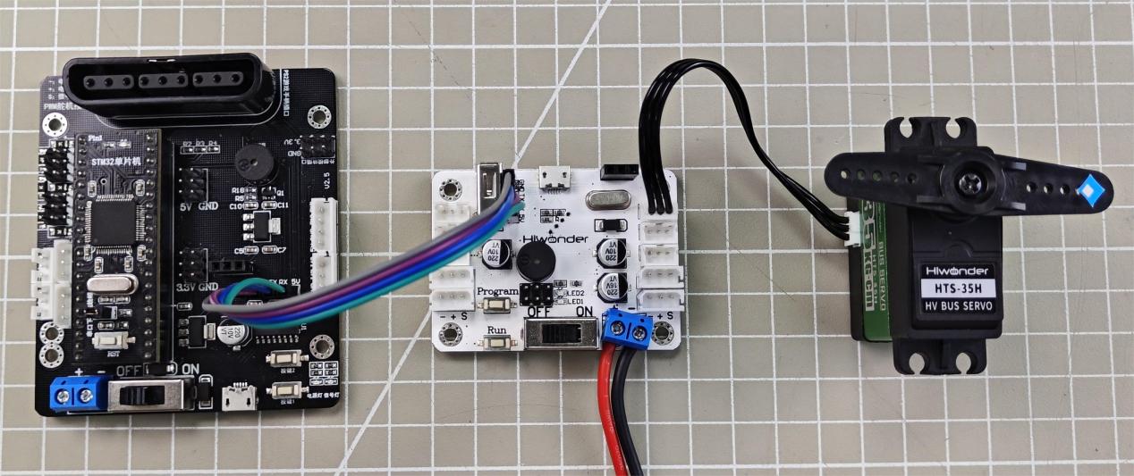
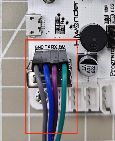
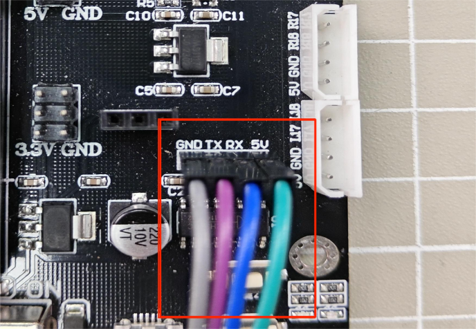
This example uses an Arduino development board and a bus servo controller, powered by a 7.4V 6000mAh lithium battery, or an 11.1V battery for high-voltage servos. Connect the serial port of the bus servo controller to the serial port of the open-source servo controller.

Note
When using Hiwonder’s lithium battery, connect the battery cable with the red wire to the positive (+) terminal and the black wire to the negative (–) terminal of the DC port.
Before connecting the battery cables, make sure they are not already attached to the lithium battery. This prevents the risk of a short circuit caused by accidental contact between the positive and negative wires.
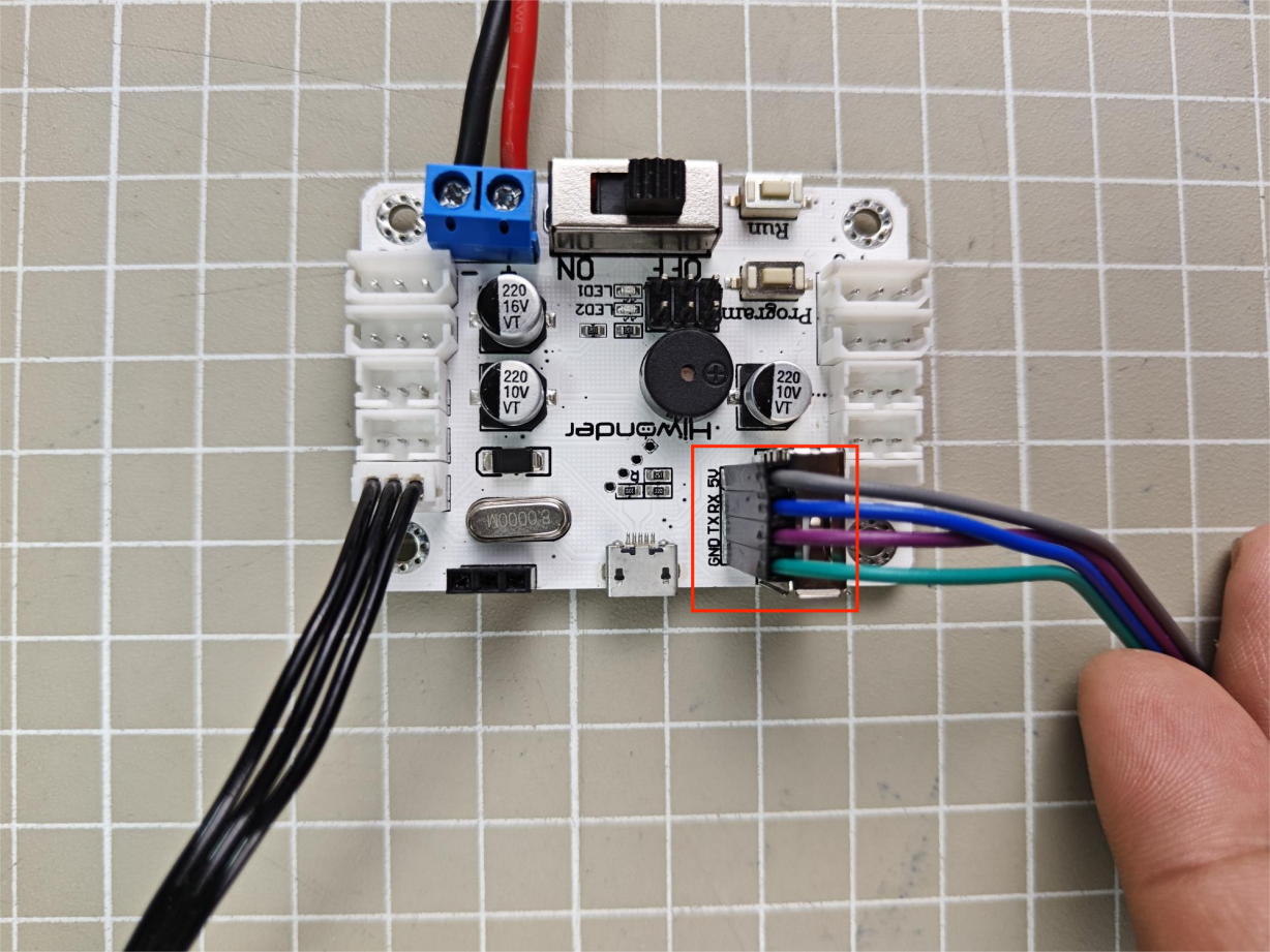
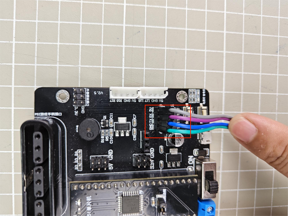
When connecting the serial ports, make sure to cross the RX and TX pins. As shown in the two diagrams above.
Environment Configuration
Install Arduino software on PC. The software package and installation instruction are stored in Appendix -> Arduino Installation Package.
2.2.2 Development Case
Case 1 Control a Single Servo
In this example, the serial port is used to send instructions to the bus servo controller, which then controls the servo to move.
Run Program
(1) Open the LobotServoController.ino program located at:
Case 1 Control a Single Servo\LobotServoController.
(2) After opening the program, go to Sketch → Include Library → Add .ZIP Library, and select the LobotServoController.zip file located in the same path to add it. If adding the library fails, please refer to the Arduino IDE user manual. 2.Bus_Servo_Controller_Secondary_Development.md (3) Connect the Arduino controller to your computer via a USB cable. In the toolbar, set the board type to Arduino UNO, and select the correct port.
Note
The port number is not fixed. The Arduino IDE will display the board model next to the corresponding port number.

(4) After connecting, click the icon  to upload. Once the upload is complete, turn on the bus servo controller’s power switch, and Servo ID 1 will start moving.
Note
If you see an upload failure message, try disconnecting the bus servo controller from the Arduino board before uploading. After the upload completes, reconnect it to the Arduino.
Project Outcome
After running the program, the servo will continuously swing back and forth between position 0 and position 1000, with a 1.5-second interval.
Program Brief Analysis
(1) Import Necessary Libraries
1 | #include <LobotServoController.h>
|
The library includes the necessary modules for communicating with the bus servo controller. You can use the predefined variables and functions in it to control the servo.
(2) UART Initialization
3 | LobotServoController myse; //Instantiate servo control object (实例化舵机控制对象) |
Create an instance of the servo control object and set the baud rate to 9600.
(3) Control Servo Movement
10 11 12 13 14 15 | void loop() { myse.moveServo(1,0,800); //Move servo 1 to position 0 in 800 ms (1号舵机800ms移动至0位置) delay(1500); myse.moveServo(1,1000,800); //Move servo 1 to position 1000 in 800 ms (1号舵机800ms移动至1000位置) delay(1500); } |
After the main program starts, it calls the moveServo() function to move Servo ID 1 from position 0 to 1000.
Case 2 Control a Single Servo’s Speed
In this example, the serial port is used to send instructions to the bus servo controller, which then controls the servo to move.
Run Program
(1) Open the LobotServoController.ino program located at:
Case 2 Control a Single Servo’s Speed\LobotServoController.
(2) After opening the program, go to Sketch → Include Library → Add .ZIP Library, and select the LobotServoController.zip file located in the same path to add it. If adding the library fails, please refer to the Arduino IDE user manual.
(3) Connect the Arduino controller to your computer via a USB cable.
In the toolbar, set the board type to Arduino UNO, and select the correct port.
Note
The port number is not fixed. The Arduino IDE will display the board model next to the corresponding port number.
(4) After connecting, click the icon  to upload. Once the upload is complete, turn on the bus servo controller’s power switch, and Servo ID 1 will start moving.
Note
If you see an upload failure message, try disconnecting the bus servo controller from the Arduino board before uploading. After the upload completes, reconnect it to the Arduino.
Project Outcome
After running the program, the servo will rotate from position 0 to position 1000 at a speed set to 800 ms, and then rotate back from position 1000 to position 0 at a speed set to 1200 ms.
Program Brief Analysis
(1) Import Necessary Libraries
1 | #include <LobotServoController.h>
|
The library includes the necessary modules for communicating with the bus servo controller. You can use the predefined variables and functions in it to control the servo.
(2) UART Initialization
3 4 5 6 7 8 9 | LobotServoController myse; //Instantiate the servo control object (实例化舵机控制的对象) void setup() { Serial.begin(9600); while(!Serial); } |
Create an instance of the servo control object and set the baud rate to 9600.
(3) Control Servo Movement
11 12 13 14 15 16 17 18 19 20 | void loop() { myse.moveServo(1,0,500); //Servo 1 moves to position 0 in 800 ms (1号舵机800ms移动至0位置) delay(1200); myse.moveServo(1,1000,500); //Servo 1 moves to position 1000 in 800 ms (1号舵机800ms移动至1000位置) delay(1200); myse.moveServo(1,0,1500); //Servo 1 moves to position 0 in 1200 ms (1号舵机1200ms移动至0位置) delay(2000); myse.moveServo(1,1000,1500); //Servo 1 moves to position 1000 in 1200 ms (1号舵机1200ms移动至1000位置) delay(2000); } |
After the main program starts, it calls the moveServo() function to control the position and movement time of Servo ID 1. By adjusting the movement time parameter, you can control the servo’s rotation speed.
Case 3 Control Multiple Servos
In this example, the serial port is used to send instructions to the bus servo controller, which then controls multiple servos to move.
Run Program
(1) Open the LobotServoController.ino program located at:
Case 3 Control Multiple Servos\LobotServoController.
(2) After opening the program, go to Sketch → Include Library → Add .ZIP Library, and select the LobotServoController.zip file located in the same path to add it. If adding the library fails, please refer to the Arduino IDE user manual.
(3) Connect the Arduino controller to your computer via a USB cable.
In the toolbar, set the board type to Arduino UNO, and select the correct port.
Note
The port number is not fixed. The Arduino IDE will display the board model next to the corresponding port number.
(4) After connecting, click the icon to upload. Once the upload is complete, turn on the bus servo controller’s power switch, and Servo ID 1 will start moving.
Note
If you see an upload failure message, try disconnecting the bus servo controller from the Arduino board before uploading. After the upload completes, reconnect it to the Arduino.
Project Outcome
After running the program, Servo 1 and Servo 2 will move back and forth between position 0 and position 1000, with an interval of 1.5 seconds. The number of servos you can control depends on the available ports on the controller. In this example, only two servos are used, but you can modify the code to control more servos.
Program Brief Analysis
(1) Import Necessary Libraries
1 | #include <LobotServoController.h>
|
The library includes the necessary modules for communicating with the bus servo controller. You can use the predefined variables and functions in it to control the servo.
(2) UART Initialization
3 4 5 6 7 8 | LobotServoController myse; //Instantiate the servo control object (实例化舵机控制对象) void setup() { Serial.begin(9600); while(!Serial); } |
Create an instance of the servo control object and set the baud rate to 9600.
(3) Control Servo Movement
10 11 12 13 14 15 16 17 18 19 20 21 22 23 24 25 | LobotServo servos[2]; // Servo ID and position structure array (舵机ID位置结构数组) void loop() { servos[0].ID = 1; //Servo 1 (1号舵机) servos[0].Position = 0; //Position 0 (0位置) servos[1].ID = 2; //Servo 2 (2号舵机) servos[1].Position = 0; //Position 0 (0位置) myse.moveServos(servos,2,800); //控制两个舵机,移动时间800ms,ID和位置由servos指定 delay(1500); servos[0].ID = 1; //Servo 1 (1号舵机) servos[0].Position = 1000; //Position 1000 (1000位置) servos[1].ID = 2; //Servo 2 (2号舵机) servos[1].Position = 1000; //Position 1000 (1000位置) myse.moveServos(servos,2,800); //Control two servos, move time 800 ms, ID and position specified by servos (控制两个舵机,移动时间800ms,ID和位置由servos指定) delay(1500); } |
Before the main program runs, you first define an array containing the servo IDs and target positions. Then, by calling the moveServos() function, the data in the array is sent to the servo controller, allowing you to control multiple servos at once.
Case 4 Central Position & Deviation Adjustment
In this example, the serial port is used to send instructions to the bus servo controller, which then controls the servo to move to central position and adjusts its deviation.
The central position is considered the initial position of the servo and serves as the zero point for rotating in both positive and negative directions. Therefore, the servo should be adjusted to its central position before attaching the servo horn.
Servo deviation is caused by the spacing of the splines on the servo arm—a mechanical limitation that can be corrected through software. In robotics, if this deviation is not addressed, it may restrict the movement of the robot and negatively impact certain motion behaviors.
Run Program
(1) Open the LobotServoController.ino program located at:
Case 4 Central Position & Deviation Adjustment\LobotServoController.
(2) After opening the program, go to Sketch → Include Library → Add .ZIP Library, and select the LobotServoController.zip file located in the same path to add it. If adding the library fails, please refer to the Arduino IDE user manual.
(3) Connect the Arduino controller to your computer via a USB cable.
In the toolbar, set the board type to Arduino UNO, and select the correct port.
Note
The port number is not fixed. The Arduino IDE will display the board model next to the corresponding port number.
(4) After connecting, click the icon to upload. Once the upload is complete, turn on the bus servo controller’s power switch, and Servo ID 1 will start moving.
Note
If you see an upload failure message, try disconnecting the bus servo controller from the Arduino board before uploading. After the upload completes, reconnect it to the Arduino.
Project Outcome
The servo first returns to the central position. After a short delay, it rotates to the specified deviation angle and holds that position.
Program Brief Analysis
(1) Import Necessary Libraries
1 | #include <LobotServoController.h>
|
The library includes the necessary modules for communicating with the bus servo controller. You can use the predefined variables and functions in it to control the servo.
(2) UART Initialization
2 3 4 5 6 7 | LobotServoController myse; //Instantiate the servo control object (实例化舵机控制对象) void setup() { Serial.begin(9600); while(!Serial); } |
Create an instance of the servo control object and set the baud rate to 9600.
(3) Control Servo Movement
10 11 12 13 14 15 16 17 | uint8_t deviation; //Deviation (偏差) void loop() { myse.moveServo(1,500,500); //Servo 1 moves to the central position in 500 ms (1号舵机500ms移动至中位) delay(2000); deviation = 200; myse.moveServo(1,500+deviation,200); //Servo 1 moves to the deviation position in 200 ms (1号舵机200ms移动至偏差位置) while(1); } |
Before the main program runs, define the servo deviation. First, move the servo to its central position and hold for 2 seconds. Then, based on this central position, apply an additional deviation to move the servo to the new target position, and keep it at this deviation angle.
2.3 C51 Development
2.3.1 Getting Started
Wiring Instruction
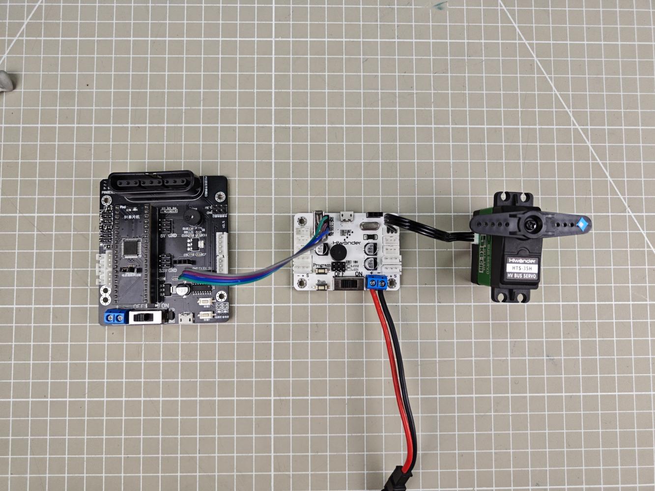
This section employs an open-source servo controller, STC15W4K32S4 microcontroller, and a bus servo controller for development, powered by a 7.4V 6000mAh lithium battery, or an 11.1V battery for high-voltage servos. Connect the serial port of the bus servo controller to the serial port of the open-source servo controller.
Note
When using Hiwonder’s lithium battery, connect the battery cable with the red wire to the positive (+) terminal and the black wire to the negative (–) terminal of the DC port.
Before connecting the battery cables, make sure they are not already attached to the lithium battery. This prevents the risk of a short circuit caused by accidental contact between the positive and negative wires.
When connecting the serial ports, make sure to cross the RX and TX pins. As shown in the two diagrams above.
Environment Configuration
Install Keil4 software on PC. The software package is stored in Appendix->C51 Software. For the detailed operations of Keil4, please refer to the relevant tutorials.
2.3.2 Development Case
Case 1 Control a Single Servo
In this example, the serial port is used to send instructions to the bus servo controller, which then controls the servo to move.
Run Program
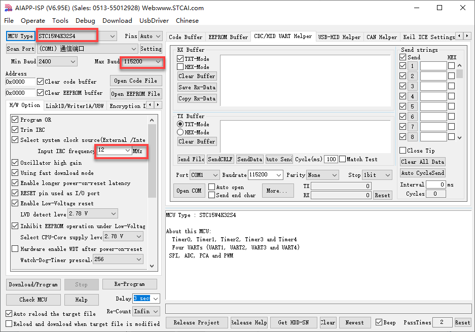
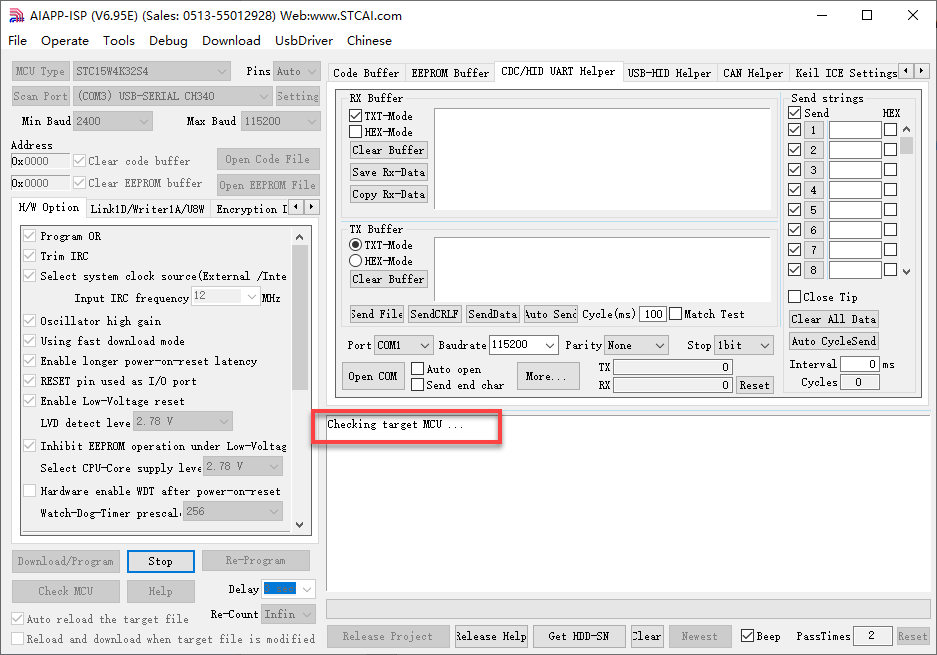
(1) Open the AIapp-ISP-v6.95E in Appendix->C51 Software.
The AIapp-ISP-v6.95E configuration is shown as follow:
| NO. | Actions | NO. | Actions |
|---|---|---|---|
| 1 | Stand: stand() |
10 | Sit:sit() |
| 2 | Move a step forward: forward() |
11 | Left/ right foot kick: kick_ball_left/right() |
| 3 | Step backwards: back() |
12 | Dance: moonwalk() |
| 4 | Turn left: turn_left() |
13 | Lie down: lie_down() |
| 5 | Turn right: turn_right() |
14 | Have a good stretch: temp() |
| 6 | Box: boxing() |
15 | Bow: bow() |
| 7 | Push up: push_up() |
16 | Kick red ball: kick_ball('red') |
| 8 | Handshake: shake_hands() |
17 | Trace red line: visual_patrol('red') |
| 9 | Nod: nod() |
18 |
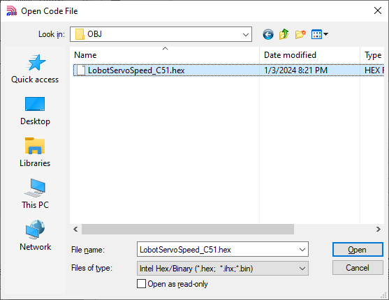
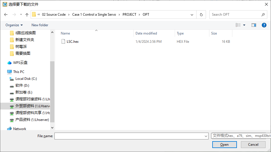
(2) Click “Open Code File” and find the hex file in Case 1 Control a Single Servo/OBJ/LobotServoTurn_C51.

(3) After opening the program file, click “Download/Program” to upload the code to the 51 microcontroller.
Note
Before uploading, remove the jumper cap from the 51 microcontroller. Once the AIapp-ISP-v6.95E tool in the lower-right corner shows that it is detecting the target device, reinsert the jumper cap. The upload process will begin automatically.
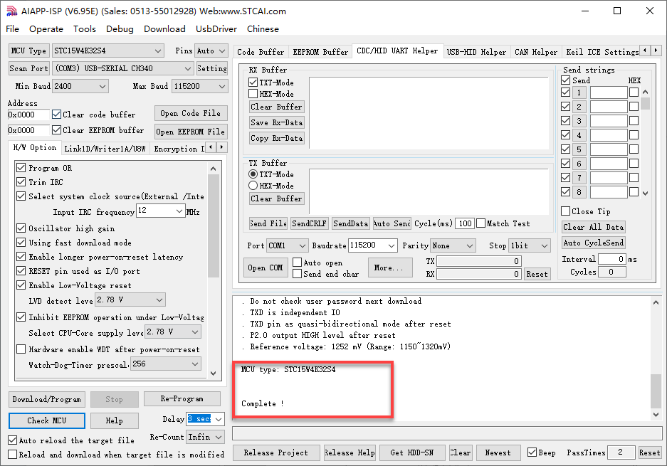
Once the upload is complete, turn on the bus servo controller’s power switch, and Servo ID 1 will start moving.
Project Outcome
After running the program, the servo will continuously swing back and forth between position 0 and position 1000, with a 1.5-second interval.
Program Brief Analysis
(1) Import Necessary Libraries
① Import the package in main.c program:
1 2 | #include "include.h" #include "lsc2d.h" |
② Import the package in include.h file:
4 5 6 7 | #include <STC15.h> #include <intrins.h> #include "typedef.h" #include "lsc2d.h" |
The library includes the necessary modules for communicating with the bus servo controller. You can use the predefined variables and functions in it to control the servo.
(2) UART Initialization
3 4 5 6 7 8 9 10 11 12 | void InitUart(void) { SCON = 0x50; AUXR = 0x16; AUXR |= 0x01; IE2 = 0x10; T2L = (65536 - (FOSC/4/UART4_BAUD)); //Set baud rate reload value T2H = (65536 - (FOSC/4/UART4_BAUD))>>8; } |
In the uart.c file, initialize the UART by enabling UART1 through the SCON register. The AUCR and IE2 registers are configured so that UART1 uses Timer 2 to generate the baud rate. Set the initial count values of T2L and T2H to configure the baud rate to 9600.
(3) Control Servo Movement
22 23 24 25 26 27 28 29 30 31 32 33 34 35 | int main(void) { InitUart(); EA = 1; while(1) { moveServo(1, 0, 800); //Servo 1, move to position 0, duration 800ms (1ºÅ¶æ»ú£¬×ª¶¯µ½Î»ÖÃ0£¬ÓÃʱ800ms) DelayMs(1500); //Delay function, here delay for 1500ms (ÑÓʱ³ÌÐò£¬ÕâÀïÑÓʱ1500ms) moveServo(1, 1000, 800); // Servo 1, move to position 1000, duration 800ms (1ºÅ¶æ»ú£¬×ª¶¯µ½Î»ÖÃ1000£¬ÓÃʱ800ms) DelayMs(1500); } } |
Before running the main program, call the InitUart() function to initialize the UART. Then, use functions from the lsc2d.c file to send data to the bus servo controller and control the servo’s movement.
Case 2 Control a Single Servo’s Speed
In this example, the serial port is used to send instructions to the bus servo controller, which then controls the servo to move.
Run Program
(1) Open the AIapp-ISP-v6.95E in Appendix->C51 Software:
The AIapp-ISP-v6.95E configuration is shown as follow:
(2) Click “Open Code File” and find the hex file in Case 2 Control a Single Servo’s Speed/LobotServoSpeed_C51/OBJ.
(3) After opening the program file, click “Download/Program” to upload the code to the 51 microcontroller.
Note
Before uploading, remove the jumper cap from the 51 microcontroller. Once the AIapp-ISP-v6.95E tool in the lower-right corner shows that it is detecting the target device, reinsert the jumper cap. The upload process will begin automatically.
Once the upload is complete, turn on the bus servo controller’s power switch, and Servo ID 1 will start moving.
Project Outcome
After running the program, the servo will rotate from position 0 to position 1000 at a speed set to 800 ms, and then rotate back from position 1000 to position 0 at a speed set to 1200 ms.
Program Brief Analysis
(1) Import Necessary Libraries
① Import the package in main.c program:
1 2 | #include "include.h" #include "lsc2d.h" |
② Import the package in include.h file:
4 5 6 7 | #include <STC15.h> #include <intrins.h> #include "typedef.h" #include "lsc2d.h" |
The library includes the necessary modules for communicating with the bus servo controller. You can use the predefined variables and functions in it to control the servo.
(2) UART Initialization
3 4 5 6 7 8 9 10 11 12 | void InitUart(void) { SCON = 0x50; AUXR = 0x16; AUXR |= 0x01; IE2 = 0x10; T2L = (65536 - (FOSC/4/UART4_BAUD)); //Set baud rate reload value T2H = (65536 - (FOSC/4/UART4_BAUD))>>8; } |
In the uart.c file, initialize the UART by enabling UART1 through the SCON register. The AUCR and IE2 registers are configured so that UART1 uses Timer 2 to generate the baud rate. Set the initial count values of T2L and T2H to configure the baud rate to 9600.
(3) Main Program
22 23 24 25 26 27 28 29 30 31 32 33 34 35 36 37 38 39 40 41 | int main(void) { InitUart(); EA = 1; while(1) { moveServo(1, 0, 800); //Servo 1, move to position 0, duration 800ms DelayMs(1500); moveServo(1, 1000, 800); //Servo 1, move to position 1000, duration 800ms DelayMs(1500); moveServo(1, 0, 1200); //Servo 1, move to position 0, duration 1200ms DelayMs(1500); moveServo(1, 1000, 1200); //Servo 1, move to position 1000, duration 1200ms DelayMs(1500); } } |
Before running the main program, call the InitUart() function to initialize the UART. Then, use functions from the lsc2d.c file to send data to the bus servo controller, enabling the servos to rotate at different speeds.
Case 3 Control Multiple Servos
In this example, the serial port is used to send instructions to the bus servo controller, which then controls multiple servos to move.
Run Program
(1) Open the AIapp-ISP-v6.95E in Appendix->C51 Software:
The AIapp-ISP-v6.95E configuration is shown as follow:
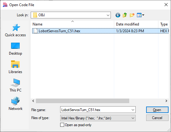
(2) Click “Open Code File” and find the hex file in Case 3 Control Multiple Servos/OBJ/LobotServosTurn_C51.
(3) After opening the program file, click “Download/Program” to upload the code to the 51 microcontroller.
Note
Before uploading, remove the jumper cap from the 51 microcontroller. Once the AIapp-ISP-v6.95E tool in the lower-right corner shows that it is detecting the target device, reinsert the jumper cap. The upload process will begin automatically.
Project Outcome
After running the program, Servo 1 and Servo 2 will move back and forth between position 0 and position 1000, with an interval of 1.5 seconds. The number of servos you can control depends on the available ports on the controller. In this example, only two servos are used, but you can modify the code to control more servos.
Program Brief Analysis
(1) Import Necessary Libraries
① Import the package in main.c program:
1 2 | #include "include.h" #include "lsc2d.h" |
② Import the package in include.h file:
4 5 6 7 | #include <STC15.h> #include <intrins.h> #include "typedef.h" #include "lsc2d.h" |
The library includes the necessary modules for communicating with the bus servo controller. You can use the predefined variables and functions in it to control the servo.
(2) UART Initialization
3 4 5 6 7 8 9 10 11 12 | void InitUart(void) { SCON = 0x50; AUXR = 0x16; AUXR |= 0x01; IE2 = 0x10; T2L = (65536 - (FOSC/4/UART4_BAUD)); //Set baud rate reload value T2H = (65536 - (FOSC/4/UART4_BAUD))>>8; } |
In the uart.c file, initialize the UART by enabling UART1 through the SCON register. The AUCR and IE2 registers are configured so that UART1 uses Timer 2 to generate the baud rate. Set the initial count values of T2L and T2H to configure the baud rate to 9600.
(3) Define Servo Structure
22 | LobotServo servos[3]; //Define servo structure array |
Store the servos to be controlled and their related information in the LobotServo structure, which is mainly used for controlling multiple servos.
(4) Control Servo Movement
24 25 26 27 28 29 30 31 32 33 34 35 36 37 38 39 40 41 42 43 44 45 46 47 48 49 50 51 | int main(void) { InitUart(); EA = 1; servos[0].ID = 1; //Set servo ID servos[1].ID = 2; servos[2].ID = 3; while(1) { servos[0].Position = 0; //Set servo position to 0 servos[1].Position = 0; servos[2].Position = 0; moveServosByArray(servos, 3, 800); //Move 3 servos to specified positions, run time 800ms DelayMs(1500); servos[0].Position = 1000; //Change position to 1000 servos[1].Position = 1000; servos[2].Position = 1000; moveServosByArray(servos, 3, 800); //Move 3 servos to position 1000, run time 800ms DelayMs(1500); } } |
The servo information stored in the structure is sent to the bus servo controller via the serial port. The controller parses the received commands and moves each corresponding servo to its specified position.
Case 4 Central Position & Deviation Adjustment
In this example, the serial port is used to send instructions to the bus servo controller, which then controls the servo to move to central position and adjusts its deviation.
The central position is considered the initial position of the servo and serves as the zero point for rotating in both positive and negative directions. Therefore, the servo should be adjusted to its central position before attaching the servo horn.
Servo deviation is caused by the spacing of the splines on the servo arm—a mechanical limitation that can be corrected through software. In robotics, if this deviation is not addressed, it may restrict the movement of the robot and negatively impact certain motion behaviors.
Run Program
(1) Open the AIapp-ISP-v6.95E in Software->C51 Software:
The AIapp-ISP-v6.95E configuration is shown as follow:
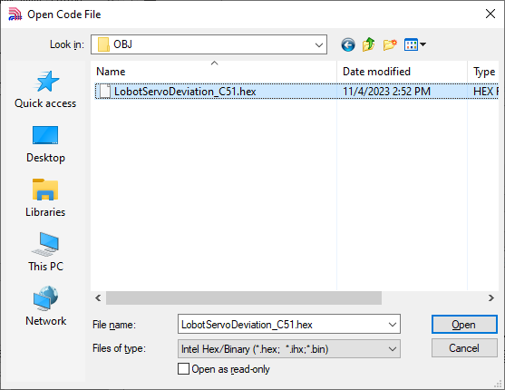
(2) Click “Open Code File” and find the hex file in Case 4 Central Position & Deviation Adjustment/LobotServosDeviation_C51/OBJ.
(3) After opening the program file, click “Download/Program” to upload the code to the 51 microcontroller.
Note
Before uploading, remove the jumper cap from the 51 microcontroller. Once the AIapp-ISP-v6.95E tool in the lower-right corner shows that it is detecting the target device, reinsert the jumper cap. The upload process will begin automatically.
Project Outcome
The servo first returns to the central position. After a short delay, it rotates to the specified deviation angle and holds that position.
Program Brief Analysis
(1) Import Necessary Libraries
① Import the package in main.c program:
1 2 | #include "include.h" #include "lsc2d.h" |
② Import the package in include.h file:
4 5 6 7 | #include <STC15.h> #include <intrins.h> #include "typedef.h" #include "lsc2d.h" |
The library includes the necessary modules for communicating with the bus servo controller. You can use the predefined variables and functions in it to control the servo.
(2) UART Initialization
3 4 5 6 7 8 9 10 11 12 | void InitUart(void) { SCON = 0x50; AUXR = 0x16; AUXR |= 0x01; IE2 = 0x10; T2L = (65536 - (FOSC/4/UART4_BAUD)); //Set baud rate reload value T2H = (65536 - (FOSC/4/UART4_BAUD))>>8; } |
In the uart.c file, initialize the UART by enabling UART1 through the SCON register. The AUCR and IE2 registers are configured so that UART1 uses Timer 2 to generate the baud rate. Set the initial count values of T2L and T2H to configure the baud rate to 9600.
(3) Control Servo Movement
22 23 24 25 26 27 28 29 30 31 32 33 34 35 36 37 38 39 40 | uint8 deviation; //Deviation int main(void) { InitUart(); EA = 1; while(1) { moveServo(1, 500, 500); //Servo 1, move to position 500, duration 500ms DelayMs(2000); //Delay program, here delay 2000ms deviation = 200; moveServo(1, 500+deviation, 200); //Servo 1, move to position 700, duration 200ms while(1); } } |
Before the main program runs, define the servo deviation. First, move the servo to its central position and hold for 2 seconds. Then, based on this central position, apply an additional deviation to move the servo to the new target position, and keep it at this deviation angle.
2.4 STM32 Development
2.4.1 Getting Started
Wiring Instruction
This section employs an open-source servo controller, STC15W4K32S4 microcontroller, and a bus servo controller for development, powered by a 7.4V 6000mAh lithium battery, or an 11.1V battery for high-voltage servos. Connect the serial port of the bus servo controller to the serial port of the open-source servo controller.
Note
When using Hiwonder’s lithium battery, connect the battery cable with the red wire to the positive (+) terminal and the black wire to the negative (–) terminal of the DC port.
Before connecting the battery cables, make sure they are not already attached to the lithium battery. This prevents the risk of a short circuit caused by accidental contact between the positive and negative wires.
When connecting the serial ports, make sure to cross the RX and TX pins. As shown in the two diagrams above.
Environment Configuration
Install Keil5 software on PC. The software package is stored in Appendix->STM32 Software. For the detailed operations of Keil5, please refer to the relevant tutorials.
2.4.2 Development Case
Case 1 Control a Single Servo
In this example, the serial port is used to send instructions to the bus servo controller, which then controls the servo to move.
Run Program
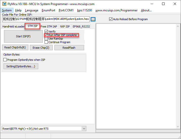
(1) Open the mcuisp download tool in Appendix->STM32 Software:

The mcuisp configuration is shown as follow:
(2) Click  , then find the hex file in the following folder:
Case 1 Control a Single Servo\PROJECT\OPT
(3) After opening the program file, click Start ISP(P) to download the program to the STM32 microcontroller.
Note
Before downloading, remove the jumper cap from the STM32 microcontroller and press the reset button. When “Mission Completed, Anything Ok!!!” appears in the bottom-right corner of mcuisp, the download is complete. Finally, reinsert the jumper cap back onto the STM32 microcontroller.
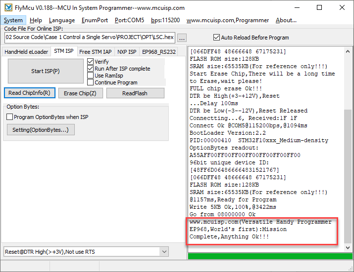
Once the upload is complete, turn on the bus servo controller’s power switch, then press the reset button on the STM32 microcontroller, and Servo ID 1 will start moving.
Project Outcome
After running the program, the servo will continuously swing back and forth between position 0 and position 1000, with a 1.5-second interval.
Program Brief Analysis
(1) Import Necessary Libraries
① Import the package in main.c program:
1 2 3 4 | #include "delay.h" #include "uart.h" #include "LobotServoController.h" #include "bool.h" |
The library includes the necessary modules for communicating with the bus servo controller. You can use the predefined variables and functions in it to control the servo.
6 7 8 9 10 | void delay_s(int s) { for(;s>0;s--) delay_ms(1000); } |
In the main.c file, there is a delay function used to create delays in seconds (s).
(2) UART Initialization
39 40 41 42 43 44 45 46 47 48 49 50 51 52 53 54 55 56 57 58 59 60 61 62 63 64 65 66 67 68 69 | void uartInit(u32 bound) { GPIO_InitTypeDef GPIO_InitStructure; USART_InitTypeDef USART_InitStructure; RCC_APB2PeriphClockCmd(RCC_APB2Periph_USART1 | RCC_APB2Periph_GPIOA | RCC_APB2Periph_AFIO, ENABLE); //USART1_TX PA9 GPIO_InitStructure.GPIO_Pin = GPIO_Pin_9; GPIO_InitStructure.GPIO_Speed = GPIO_Speed_50MHz; GPIO_InitStructure.GPIO_Mode = GPIO_Mode_AF_PP; GPIO_Init(GPIOA, &GPIO_InitStructure); //USART1_RX PA10 GPIO_InitStructure.GPIO_Pin = GPIO_Pin_10; GPIO_InitStructure.GPIO_Mode = GPIO_Mode_IN_FLOATING; GPIO_Init(GPIOA, &GPIO_InitStructure); //USART configuration (USART配置) USART_InitStructure.USART_BaudRate = bound;//Baud rate (波特率) USART_InitStructure.USART_WordLength = USART_WordLength_8b; //Data bits (数据位) USART_InitStructure.USART_StopBits = USART_StopBits_1; //Stop bit (停止位) USART_InitStructure.USART_Parity = USART_Parity_No; //Parity bit (校验位) USART_InitStructure.USART_HardwareFlowControl = USART_HardwareFlowControl_None; //Flow control (流控制) USART_InitStructure.USART_Mode = USART_Mode_Rx | USART_Mode_Tx; //Enable RX and TX (发送接收) USART_Init(USART1, &USART_InitStructure); uartNVICInit(); USART_ITConfig(USART1, USART_IT_RXNE, ENABLE); USART_Cmd(USART1, ENABLE); } |
In uart.c, the UART is initialized by configuring PA9 as TX (transmit) and PA10 as RX (receive). The USART is configured with 8 data bits, 1 stop bit, no parity, no flow control, and in read/write mode.
(3) Control Servo Movement
12 13 14 15 16 17 18 19 20 21 22 23 24 25 | int main(void) { SystemInit();//System clock and related initialization delay_init(72); //Initialize delay module NVIC_PriorityGroupConfig(NVIC_PriorityGroup_2);//Set NVIC interrupt priority grouping: 2 bits preemption priority, 2 bits subpriority uartInit(9600);//Initialize UART with baud rate 9600 while(1){ moveServo(1, 1000, 1200); //Move servo 1 to position 1000 delay_s(2); moveServo(1, 0, 1200); //Move servo 1 to position 0 delay_s(2); } } |
Before running the main program, call the SystemInit() function to initialize the system clock, call delay_init(72) to initialize the delay module, and initialize the NVIC interrupt controller, which uses the system clock to generate interrupts for providing precise delays. Finally, initialize the UART with a baud rate of 9600.
In the while loop, the moveServo() function is called to send data to the bus servo controller, controlling the servo’s movement.
Case 2 Control a Single Servo’s Speed
In this example, the serial port is used to send instructions to the bus servo controller, which then controls the servo to move.
Run Program
(1) Open the mcuisp download tool in Appendix->STM32 Software:

The mcuisp configuration is shown as follow:
(2) Click , then find the hex file in the following folder:
Case 2 Control a Single Servo’s Speed\PROJECT\OPT
(3) After opening the program file, click Start ISP(P) to download the program to the STM32 microcontroller.
Note
Before downloading, remove the jumper cap from the STM32 microcontroller and press the reset button. When “Mission Completed, Anything Ok!!!” appears in the bottom-right corner of mcuisp, the download is complete. Finally, reinsert the jumper cap back onto the STM32 microcontroller.
Once the upload is complete, turn on the bus servo controller’s power switch, then press the reset button on the STM32 microcontroller, and Servo ID 1 will start moving.
Project Outcome
After running the program, the servo will rotate from position 0 to position 1000 at a speed set to 1200 ms, and then rotate back from position 1000 to position 0 at a speed set to 500 ms.
Program Brief Analysis
(1) Import Necessary Libraries
① Import the package in main.c program:
1 2 3 4 | #include "delay.h" #include "uart.h" #include "LobotServoController.h" #include "bool.h" |
The library includes the necessary modules for communicating with the bus servo controller. You can use the predefined variables and functions in it to control the servo.
6 7 8 9 10 | void delay_s(int s) { for(;s>0;s--) delay_ms(1000); } |
In the main.c file, there is a delay function used to create delays in seconds (s).
(2) UART Initialization
39 40 41 42 43 44 45 46 47 48 49 50 51 52 53 54 55 56 57 58 59 60 61 62 63 64 65 66 67 68 69 | void uartInit(u32 bound) { GPIO_InitTypeDef GPIO_InitStructure; USART_InitTypeDef USART_InitStructure; RCC_APB2PeriphClockCmd(RCC_APB2Periph_USART1 | RCC_APB2Periph_GPIOA | RCC_APB2Periph_AFIO, ENABLE); //USART1_TX PA9 GPIO_InitStructure.GPIO_Pin = GPIO_Pin_9; GPIO_InitStructure.GPIO_Speed = GPIO_Speed_50MHz; GPIO_InitStructure.GPIO_Mode = GPIO_Mode_AF_PP; GPIO_Init(GPIOA, &GPIO_InitStructure); //USART1_RX PA10 GPIO_InitStructure.GPIO_Pin = GPIO_Pin_10; GPIO_InitStructure.GPIO_Mode = GPIO_Mode_IN_FLOATING; GPIO_Init(GPIOA, &GPIO_InitStructure); //USART configuration (USART配置) USART_InitStructure.USART_BaudRate = bound;//Baud rate (波特率) USART_InitStructure.USART_WordLength = USART_WordLength_8b; //Data bits (数据位) USART_InitStructure.USART_StopBits = USART_StopBits_1; //Stop bit (停止位) USART_InitStructure.USART_Parity = USART_Parity_No; //Parity bit (校验位) USART_InitStructure.USART_HardwareFlowControl = USART_HardwareFlowControl_None; //Flow control (流控制) USART_InitStructure.USART_Mode = USART_Mode_Rx | USART_Mode_Tx; //Enable RX and TX (发送接收) USART_Init(USART1, &USART_InitStructure); uartNVICInit(); USART_ITConfig(USART1, USART_IT_RXNE, ENABLE); USART_Cmd(USART1, ENABLE); } |
In uart.c, the UART is initialized by configuring PA9 as TX (transmit) and PA10 as RX (receive). The USART is configured with 8 data bits, 1 stop bit, no parity, no flow control, and in read/write mode.
(3) Main Program
12 13 14 15 16 17 18 19 20 21 22 23 24 25 26 27 28 29 30 | int main(void) { SystemInit();//System clock and other initialization delay_init(72); //Initialize delay function NVIC_PriorityGroupConfig(NVIC_PriorityGroup_2);//Set NVIC interrupt grouping to Group 2: 2 bits preemption priority, 2 bits subpriority uartInit(9600);//Initialize UART at 9600 baud rate while(1){ moveServo(1, 1000, 1200); //Move servo 1 to position 1000 delay_s(2); moveServo(1, 0, 1200); //Move servo 1 to position 0 delay_s(2); moveServo(1, 1000, 500); //Move servo 1 to position 1000 delay_s(1); moveServo(1, 0, 500); //Move servo 1 to position 0 delay_s(1); } } |
In the while loop, the moveServo() function is called to move Servo ID 1 to position 1000 in 1200 ms, and then back to position 0. Then, in the same way, move the servo to the desired position in 500 ms.
Case 3 Control Multiple Servos
In this example, the serial port is used to send instructions to the bus servo controller, which then controls multiple servos to move.
Run Program
(1) Open the mcuisp download tool in Appendix->STM32 Software:
The mcuisp configuration is shown as follow:
(2) Click , then find the hex file in the following folder:
Source Code\Case 3 Control Multiple Servos\PROJECT\OPT
(3) After opening the program file, click Start ISP(P) to download the program to the STM32 microcontroller.
Note
Before downloading, remove the jumper cap from the STM32 microcontroller and press the reset button. When “Mission Completed, Anything Ok!!!” appears in the bottom-right corner of mcuisp, the download is complete. Finally, reinsert the jumper cap back onto the STM32 microcontroller.
Once the upload is complete, turn on the bus servo controller’s power switch, then press the reset button on the STM32 microcontroller, and Servo ID 1 will start moving.
Project Outcome
After running the program, Servo 1, Servo 2 and Servo 3 will move back and forth between position 0 and position 1000, with an interval of 1.5 seconds. The number of servos you can control depends on the available ports on the controller. In this example, only two servos are used, but you can modify the code to control more servos.
Program Brief Analysis
(1) Import Necessary Libraries
① Import the package in main.c program:
1 2 3 4 | #include "delay.h" #include "uart.h" #include "LobotServoController.h" #include "bool.h" |
The library includes the necessary modules for communicating with the bus servo controller. You can use the predefined variables and functions in it to control the servo.
6 7 8 9 10 | void delay_s(int s) { for(;s>0;s--) delay_ms(1000); } |
In the main.c file, there is a delay function used to create delays in seconds (s).
(2) UART Initialization
39 40 41 42 43 44 45 46 47 48 49 50 51 52 53 54 55 56 57 58 59 60 61 62 63 64 65 66 67 68 69 | void uartInit(u32 bound) { GPIO_InitTypeDef GPIO_InitStructure; USART_InitTypeDef USART_InitStructure; RCC_APB2PeriphClockCmd(RCC_APB2Periph_USART1 | RCC_APB2Periph_GPIOA | RCC_APB2Periph_AFIO, ENABLE); //USART1_TX PA9 GPIO_InitStructure.GPIO_Pin = GPIO_Pin_9; GPIO_InitStructure.GPIO_Speed = GPIO_Speed_50MHz; GPIO_InitStructure.GPIO_Mode = GPIO_Mode_AF_PP; GPIO_Init(GPIOA, &GPIO_InitStructure); //USART1_RX PA10 GPIO_InitStructure.GPIO_Pin = GPIO_Pin_10; GPIO_InitStructure.GPIO_Mode = GPIO_Mode_IN_FLOATING; GPIO_Init(GPIOA, &GPIO_InitStructure); //USART configuration (USART配置) USART_InitStructure.USART_BaudRate = bound;//Baud rate (波特率) USART_InitStructure.USART_WordLength = USART_WordLength_8b; //Data bits (数据位) USART_InitStructure.USART_StopBits = USART_StopBits_1; //Stop bit (停止位) USART_InitStructure.USART_Parity = USART_Parity_No; //Parity bit (校验位) USART_InitStructure.USART_HardwareFlowControl = USART_HardwareFlowControl_None; //Flow control (流控制) USART_InitStructure.USART_Mode = USART_Mode_Rx | USART_Mode_Tx; //Enable RX and TX (发送接收) USART_Init(USART1, &USART_InitStructure); uartNVICInit(); USART_ITConfig(USART1, USART_IT_RXNE, ENABLE); USART_Cmd(USART1, ENABLE); } |
In uart.c, the UART is initialized by configuring PA9 as TX (transmit) and PA10 as RX (receive). The USART is configured with 8 data bits, 1 stop bit, no parity, no flow control, and in read/write mode.
(3) Define Servo Structure
12 | LobotServo servos[3]; |
Store the servos to be controlled and their related information in the LobotServo structure, which is mainly used for controlling multiple servos.
(4) Control Servo Movement
12 13 14 15 16 17 18 19 20 21 22 23 24 25 26 27 28 29 30 31 32 33 34 35 36 37 38 39 40 41 | LobotServo servos[3]; int main(void) { SystemInit();//System clock and other initialization delay_init(72); //Initialize delay function NVIC_PriorityGroupConfig(NVIC_PriorityGroup_2);// Set NVIC interrupt group 2: 2 bits preemption priority, 2 bits subpriority uartInit(9600);//Initialize UART at 9600 baud rate servos[0].ID = 1; //Set servo IDs servos[1].ID = 2; servos[2].ID = 3; while(1) { servos[0].Position = 0; //Set servo positions to 0 servos[1].Position = 0; servos[2].Position = 0; moveServosByArray(servos, 3, 1200); //Move 3 servos to specified positions with 1200ms duration delay_s(2); servos[0].Position = 1000; //Change positions to 1000 servos[1].Position = 1000; servos[2].Position = 1000; moveServosByArray(servos, 3, 1200); //Move 3 servos to position 1000 with 1200ms duration delay_s(2); } } |
The servo information stored in the structure is sent to the bus servo controller via the serial port. The controller parses the received commands and moves each corresponding servo to its specified position.
Case 4 Central Position & Deviation Adjustment
In this example, the serial port is used to send instructions to the bus servo controller, which then controls the servo to move to central position and adjusts its deviation.
The central position is considered the initial position of the servo and serves as the zero point for rotating in both positive and negative directions. Therefore, the servo should be adjusted to its central position before attaching the servo horn.
Servo deviation is caused by the spacing of the splines on the servo arm—a mechanical limitation that can be corrected through software. In robotics, if this deviation is not addressed, it may restrict the movement of the robot and negatively impact certain motion behaviors.
Run Program
(1) Open the mcuisp download tool in Appendix->STM32 Software:
The mcuisp configuration is shown as follow:
(2) Click , then find the hex file in the following folder:
Case 4 Central Position & Deviation Adjustment\PROJECT\OPT
(3) After opening the program file, click Start ISP(P) to download the program to the STM32 microcontroller.
Note
Before downloading, remove the jumper cap from the STM32 microcontroller and press the reset button. When “Mission Completed, Anything Ok!!!” appears in the bottom-right corner of mcuisp, the download is complete. Finally, reinsert the jumper cap back onto the STM32 microcontroller.
Once the upload is complete, turn on the bus servo controller’s power switch, then press the reset button on the STM32 microcontroller, and Servo ID 1 will start moving.
Project Outcome
The servo first returns to the central position. After a short delay, it rotates to the specified deviation angle and holds that position.
Program Brief Analysis
(1) Import Necessary Libraries
① Import the package in main.c program:
1 2 3 4 | #include "delay.h" #include "uart.h" #include "LobotServoController.h" #include "bool.h" |
The library includes the necessary modules for communicating with the bus servo controller. You can use the predefined variables and functions in it to control the servo.
6 7 8 9 10 | void delay_s(int s) { for(;s>0;s--) delay_ms(1000); } |
In the main.c file, there is a delay function used to create delays in seconds (s).
(2) UART Initialization
39 40 41 42 43 44 45 46 47 48 49 50 51 52 53 54 55 56 57 58 59 60 61 62 63 64 65 66 67 68 69 | void uartInit(u32 bound) { GPIO_InitTypeDef GPIO_InitStructure; USART_InitTypeDef USART_InitStructure; RCC_APB2PeriphClockCmd(RCC_APB2Periph_USART1 | RCC_APB2Periph_GPIOA | RCC_APB2Periph_AFIO, ENABLE); //USART1_TX PA9 GPIO_InitStructure.GPIO_Pin = GPIO_Pin_9; GPIO_InitStructure.GPIO_Speed = GPIO_Speed_50MHz; GPIO_InitStructure.GPIO_Mode = GPIO_Mode_AF_PP; GPIO_Init(GPIOA, &GPIO_InitStructure); //USART1_RX PA10 GPIO_InitStructure.GPIO_Pin = GPIO_Pin_10; GPIO_InitStructure.GPIO_Mode = GPIO_Mode_IN_FLOATING; GPIO_Init(GPIOA, &GPIO_InitStructure); //USART configuration (USART配置) USART_InitStructure.USART_BaudRate = bound;//Baud rate (波特率) USART_InitStructure.USART_WordLength = USART_WordLength_8b; //Data bits (数据位) USART_InitStructure.USART_StopBits = USART_StopBits_1; //Stop bit (停止位) USART_InitStructure.USART_Parity = USART_Parity_No; //Parity bit (校验位) USART_InitStructure.USART_HardwareFlowControl = USART_HardwareFlowControl_None; //Flow control (流控制) USART_InitStructure.USART_Mode = USART_Mode_Rx | USART_Mode_Tx; //Enable RX and TX (发送接收) USART_Init(USART1, &USART_InitStructure); uartNVICInit(); USART_ITConfig(USART1, USART_IT_RXNE, ENABLE); USART_Cmd(USART1, ENABLE); } |
In uart.c, the UART is initialized by configuring PA9 as TX (transmit) and PA10 as RX (receive). The USART is configured with 8 data bits, 1 stop bit, no parity, no flow control, and in read/write mode.
(3) Control Servo Movement
12 13 14 15 16 17 18 19 20 21 22 23 24 25 | int main(void) { int deviation; SystemInit();//System clock and other initialization delay_init(72); //Initialize delay function NVIC_PriorityGroupConfig(NVIC_PriorityGroup_2);//Set NVIC interrupt group 2: 2 bits preemption priority, 2 bits subpriority uartInit(9600);//Initialize UART at 9600 baud rate moveServo(1, 500, 500); // Servo 1 moves to position 500 in 500ms delay_s(2); //Delay for 2 seconds deviation = 80; moveServo(1, 500+deviation, 200); //Servo 1 moves to position 580 in 200ms while(1); } |
Before the main program runs, define the servo deviation. First, move the servo to its central position and hold for 2 seconds. Then, based on this central position, apply an additional deviation to move the servo to the new target position, and keep it at this deviation angle.
2.5 Raspberry Pi Development
2.5.1 Getting Started
Wiring Instruction
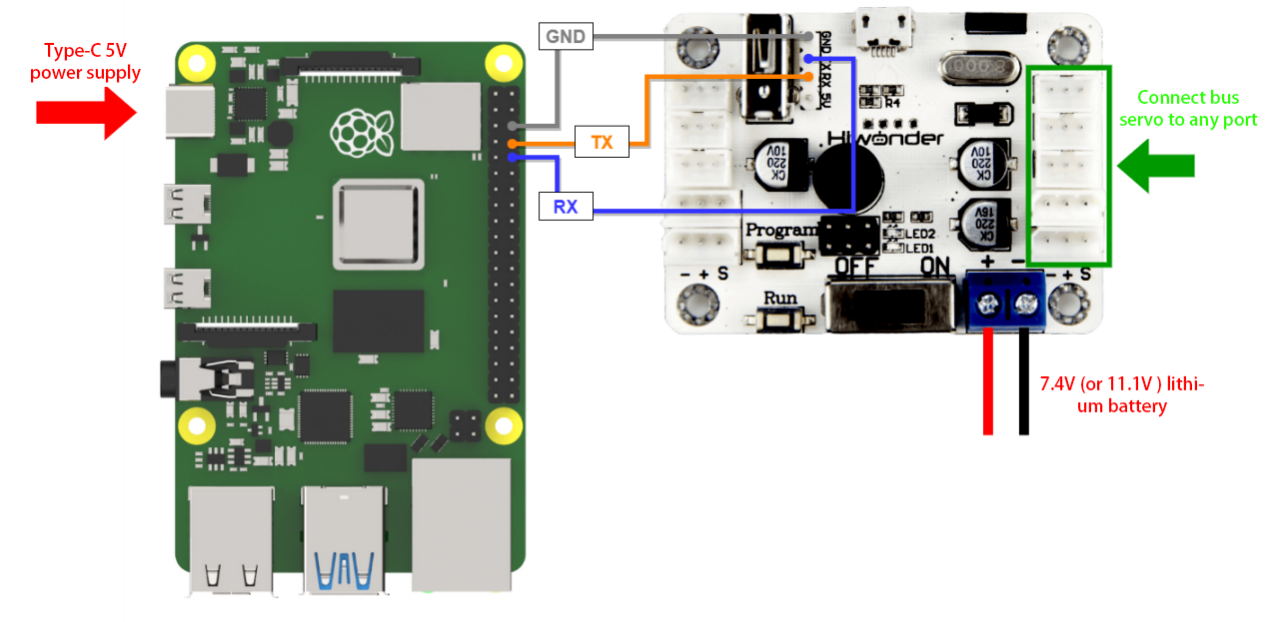
This example uses an Raspberry Pi controller and a bus servo controller, powered by a 11.1V 6000mAh lithium battery, or an 7.4V battery for low-voltage servos. Connect the serial port of the bus servo controller to the serial port of the open-source servo controller.
Note
When using Hiwonder’s lithium battery, connect the battery cable with the red wire to the positive (+) terminal and the black wire to the negative (–) terminal of the DC port.
Before connecting the battery cables, make sure they are not already attached to the lithium battery. This prevents the risk of a short circuit caused by accidental contact between the positive and negative wires.
When connecting the serial ports, make sure to cross the RX and TX pins.
Environment Configuration
Install NoMachine software on PC. The software package is stored in Appendix-> Remote Connection Software. For the detailed operations of NoMachine, please refer to the relevant tutorials.
Drag the program and SDK library files into the Raspberry Pi system image, using the desktop as an example.
Note
Make sure the library files are placed in the same directory as the program.
Open the command-line terminal and enter the following command to add execution permissions:
sudo chmod a+x Raspberry_BusServoControl_demo/
2.5.2 Development Case
Case 1 Control a Single Servo
In this example, the serial port is used to send instructions to the bus servo controller, which then controls the servo to move.
Run Program
(1) Open a new terminal and enter the following command to navigate to the program directory:
cd Raspberry_BusServoControl_demo/
(2) Run the program by entering:
python3 BusServoControl.py
Project Outcome
After running the program, the servo will continuously swing back and forth between position 0 and position 1000, with a 2-second interval.
Program Brief Analysis
(1) Import Necessary Libraries
1 | import ServoControl |
The library includes the necessary modules for communicating with the bus servo controller. You can use the predefined variables and functions in it to control the servo. In the ServoControl library file, the main method called is setBusServoMove().
① According to the communication protocol, the frame header, data length, command, and the number of servos to be controlled are first sent to the serial port.
13 14 15 16 17 18 19 20 21 22 23 24 25 26 27 28 29 30 31 32 33 34 35 | #Control single bus servo movement (控制单个总线舵机转动) def setBusServoMove(servo_id, servo_pulse, time): buf = bytearray(b'\x55\x55') #Frame header (帧头) buf.append(0x08) #Data length (数据长度) buf.append(LOBOT_CMD_SERVO_MOVE) #Command (指令) buf.append(0x01) #Number of servos to control (要控制的舵机个数) time = 0 if time < 0 else time time = 30000 if time > 30000 else time time_list = list(time.to_bytes(2, 'little')) #Time (时间) buf.append(time_list[0]) buf.append(time_list[1]) servo_id = 254 if (servo_id < 1 or servo_id > 254) else servo_id buf.append(servo_id) #id servo_pulse = 0 if servo_pulse < 0 else servo_pulse servo_pulse = 1000 if servo_pulse > 1000 else servo_pulse pulse_list = list(servo_pulse.to_bytes(2, 'little')) # buf.append(pulse_list[0]) buf.append(pulse_list[1]) serialHandle.write(buf) |
② Next, the time parameter passed in is filtered to ensure it falls within the range of (0, 30000). Values outside this range are clamped to 0 and 30000, respectively. This ensures that after the data is sent over the serial port, the controller can correctly recognize it. Then, the time parameter is split into high and low bytes using list(), where ‘little’ indicates low byte first. These two bytes are then sent to the serial port.
39 40 41 42 | buf = bytearray(b'\x55\x55') # Frame header (帧头) buf.append(0x08) #Data length (数据长度) buf.append(LOBOT_CMD_SERVO_MOVE) #Command (指令) buf.append(0x01) #要Number of servos to control (要控制的舵机个数) |
③ After that, the ID and position values are also filtered. If the incoming ID is less than 1 or greater than 254, it is clamped to 1 or 254, respectively. Note that 254 means “control all servos.” The position value is handled similarly: values below 0 are set to 0.
44 45 46 47 48 | time = 0 if time < 0 else time time = 30000 if time > 30000 else time time_list = list(time.to_bytes(2, 'little')) #Time (时间) buf.append(time_list[0]) buf.append(time_list[1]) |
④ Finally, the buf data is sent to the serial port using the write() method.
50 51 52 53 54 55 56 57 | servo_id = 254 if (servo_id < 1 or servo_id > 254) else servo_id buf.append(servo_id) #Servo ID (舵机ID) servo_pulse = 500 if servo_pulse < 500 else servo_pulse servo_pulse = 2500 if servo_pulse > 2500 else servo_pulse pulse_list = list(servo_pulse.to_bytes(2, 'little')) #Position (位置) buf.append(pulse_list[0]) buf.append(pulse_list[1]) |
35 | serialHandle.write(buf) |
(2) UART Initialization
59 | serialHandle.write(buf) |
Create an instance of the servo control object and set the baud rate to 9600.
(3) Control Servo Movement
4 5 6 7 8 9 | if __name__ == '__main__': while True: ServoControl.setBusServoMove(1, 0, 1000) time.sleep(2) ServoControl.setBusServoMove(1, 1000, 1000) time.sleep(2) |
After the main program runs in BusServoControl, it calls the setBusServoMove() function to control Servo ID 1 to move from position 0 to 1000.
Case 2 Control a Single Servo’s Speed
In this example, the serial port is used to send instructions to the bus servo controller, which then controls the servo to move.
Run Program
(1) Open a new terminal and enter the following command to navigate to the program directory:
cd Raspberry_BusServoControl_demo/
(2) Run the program by entering:
python3 BusServoSpeed.py
Project Outcome
After running the program, the servo will rotate from position 0 to position 1000 at a speed set to 800 ms, and then rotate back from position 1000 to position 0 at a speed set to 1200 ms.
Program Brief Analysis
(1) Import Necessary Libraries
1 | import ServoControl |
The library includes the necessary modules for communicating with the bus servo controller. You can use the predefined variables and functions in it to control the servo. In the ServoControl library, the main method used is setBusServoMove(), which changes the servo speed by adjusting the movement duration.
(2) UART Initialization
11 | serialHandle = serial.Serial("/dev/ttyAMA0", 9600) # Initialize serial port, baud rate 9600 (初始化串口,波特率为9600) |
Create an instance of the servo control object and set the baud rate to 9600.
(3) Control Servo Movement
3 4 5 6 7 8 9 10 11 12 | if __name__ == '__main__': while True: ServoControl.setBusServoMove(1, 0, 1200) time.sleep(2) ServoControl.setBusServoMove(1, 1000, 1200) time.sleep(2) ServoControl.setBusServoMove(1, 0, 400) time.sleep(1) ServoControl.setBusServoMove(1, 1000, 400) time.sleep(1) |
In the main program of BusServoControl, the setBusServoMove() function is first called to move Servo ID 1 from position 0 to 1000 over 1200 ms. Then, Servo ID 1 is moved back from position 1000 to 0 over 400 ms. When the rotation angle is the same, a shorter duration results in a higher speed.
Case 3 Control Multiple Servos
In this example, the serial port is used to send instructions to the bus servo controller, which then controls multiple servos to move.
Run Program
(1) Open a new terminal and enter the following command to navigate to the program directory:
cd Raspberry_BusServoControl_demo/
(2) Run the program by entering:
python3 BusServoMoveByArray.py
Project Outcome
After running the program, Servo 1 and Servo 2 will move back and forth between position 0 and position 1000, with an interval of 1.5 seconds. The number of servos you can control depends on the available ports on the controller. In this example, only two servos are used, but you can modify the code to control more servos.
Program Brief Analysis
(1) Import Necessary Libraries
1 | import ServoControl |
The library includes the necessary modules for communicating with the bus servo controller. You can use the predefined variables and functions in it to control the servo. In this example, the setBusServoMoveByArray() method is mainly used to control multiple servos.
① According to the communication protocol, the frame header, data length, command, and the number of servos to be controlled are first sent to the serial port.
13 14 15 16 17 18 19 20 21 22 23 24 25 26 27 28 29 30 31 32 33 34 35 | #Control single bus servo movement (控制单个总线舵机转动) def setBusServoMove(servo_id, servo_pulse, time): buf = bytearray(b'\x55\x55') # Frame header (帧头) buf.append(0x08) #Data length (数据长度) buf.append(LOBOT_CMD_SERVO_MOVE) #Command (指令) buf.append(0x01) #Number of servos to control (要控制的舵机个数) time = 0 if time < 0 else time time = 30000 if time > 30000 else time time_list = list(time.to_bytes(2, 'little')) #Time (时间) buf.append(time_list[0]) buf.append(time_list[1]) servo_id = 254 if (servo_id < 1 or servo_id > 254) else servo_id buf.append(servo_id) #id servo_pulse = 0 if servo_pulse < 0 else servo_pulse servo_pulse = 1000 if servo_pulse > 1000 else servo_pulse pulse_list = list(servo_pulse.to_bytes(2, 'little')) # buf.append(pulse_list[0]) buf.append(pulse_list[1]) serialHandle.write(buf) |
② Exception filtering for servo count and rotation time is performed to ensure that the bus servo controller can correctly recognize the data sent via the serial port.
39 40 41 | buf = bytearray(b'\x55\x55') # Frame header (帧头) buf.append(0x08) #Data length (数据长度) buf.append(LOBOT_CMD_SERVO_MOVE) #Command (指令) |
③ A for loop is used to send data from the servos list to the serial port. Set every two elements as one group: the first element is the servo ID, and the second is the target position. For example: list = [1, 500, 2, 300] means that servo ID 1 will move to position 500, and servo ID 2 will move to position 300. Finally, the buf data is sent to the serial port using the write() method.
67 68 69 70 71 72 73 74 75 | servos_count = 1 if servos_count < 1 else servos_count servos_count = 254 if servos_count > 254 else servos_count buf.append(servos_count) #Number of servos to control (要控制的舵机个数) time = 0 if time < 0 else time time = 30000 if time > 30000 else time time_list = list(time.to_bytes(2, 'little')) buf.append(time_list[0]) #Time (时间) buf.append(time_list[1]) |
77 78 79 80 81 82 83 84 | for i in range(servos_count): buf.append(servos[i*2]) #Servo ID (舵机ID) pos = servos[i*2+1] pos = 0 if pos < 0 else pos pos = 1000 if pos > 1000 else pos pos_list = list(pos.to_bytes(2, 'little')) buf.append(pos_list[0]) #Position (位置) buf.append(pos_list[1]) |
(2) UART Initialization
11 | serialHandle = serial.Serial("/dev/ttyAMA0", 9600) # Initialize serial port, baud rate 9600 (初始化串口,波特率为9600) |
Create an instance of the servo control object and set the baud rate to 9600.
(3) Control Servo Movement
3 4 5 6 7 8 9 10 | if __name__ == '__main__': while True: servos = [1, 1000, 2, 0] ServoControl.setMoreBusServoMove(servos, 2, 1000) time.sleep(2) servos = [1, 0, 2, 1000] ServoControl.setMoreBusServoMove(servos, 2, 1000) time.sleep(2) |
In the main program of ServoControl, a servos queue is first created to set servo ID 1 to position 1000 and servo ID 2 to position 0. Then, the setBusServoMoveByArray() function is called to move these two servos to their target positions within 1000 ms. After a 2-second delay, servo ID 1 is set to position 0 and servo ID 2 to position 1000. Then, the setBusServoMoveByArray() function is called again to move the servos, also with a duration of 1000 ms.
Case 4 Central Position & Deviation Adjustment
In this example, the serial port is used to send instructions to the bus servo controller, which then controls the servo to move to central position and adjusts its deviation.
The central position is considered the initial position of the servo and serves as the zero point for rotating in both positive and negative directions. Therefore, the servo should be adjusted to its central position before attaching the servo horn.
Servo deviation is caused by the spacing of the splines on the servo arm—a mechanical limitation that can be corrected through software. In robotics, if this deviation is not addressed, it may restrict the movement of the robot and negatively impact certain motion behaviors.
Run Program
(1) Open a new terminal and enter the following command to navigate to the program directory:
cd Raspberry_BusServoControl_demo/
(2) Run the program by entering:
python3 BusServoMedAndBias.py
Project Outcome
The servo first returns to the central position. After a short delay, it rotates to the specified deviation angle and holds that position.
Program Brief Analysis
(1) Import Necessary Libraries
1 | import ServoControl |
The library includes the necessary modules for communicating with the bus servo controller. You can use the predefined variables and functions in it to control the servo. In the ServoControl library file, the main method called is setBusServoMove().
(2) UART Initialization
11 | serialHandle = serial.Serial("/dev/ttyAMA0", 9600) # Initialize serial port, baud rate 9600 (初始化串口,波特率为9600) |
Create an instance of the servo control object and set the baud rate to 9600.
(3) Control Servo Movement
4 5 6 7 8 9 10 | if __name__ == '__main__': deviation = 30 ServoControl.setBusServoMove(1, 500, 800) time.sleep(2) ServoControl.setBusServoMove(1, 500+deviation, 800) while True: time.sleep(1) |
In the main program of BusServoControl, a variable named deviation is first created to store the deviation value. The setBusServoMove() function is initially called to move servo ID 1 to position 500 within 800 ms. After a 2-second delay, the servo is moved again based on its previous position (500) plus the deviation value, thereby achieving a software-based deviation adjustment.
2.6 Jetson Development
2.6.1 Getting Started
Wiring Instruction
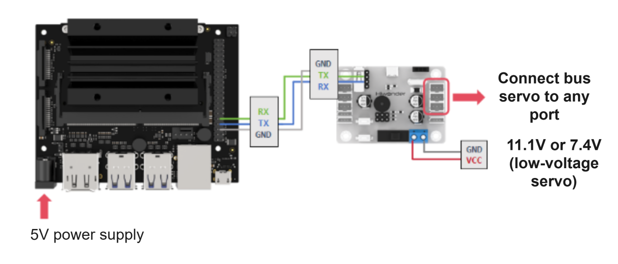
This example uses an Jetson Nano controller and a bus servo controller, powered by a 11.1V 6000mAh lithium battery, or an 7.4V battery for low-voltage servos. Connect the serial port of the bus servo controller to the serial port of the open-source servo controller.
Note
When using Hiwonder’s lithium battery, connect the battery cable with the red wire to the positive (+) terminal and the black wire to the negative (–) terminal of the DC port.
Before connecting the battery cables, make sure they are not already attached to the lithium battery. This prevents the risk of a short circuit caused by accidental contact between the positive and negative wires.
When connecting the serial ports, make sure to cross the RX and TX pins.
Environment Configuration
Install NoMachine software on PC. The software package is stored in Appendix-> Remote Connection Software . For the detailed operations of NoMachine, please refer to the relevant tutorials.
Drag the program and the SDK library files into the Raspberry Pi system image. This example places the file in the /home/hiwonder/Desktop/Jetson_BusServoControl_demo directory.
Note
Make sure the library files are placed in the same directory as the program.
Open the command-line terminal and enter the following command to add execution permissions:
sudo find /home/hiwonder/Desktop/Jetson_BusServoControl_demo -type f -name "*.py" -exec chmod a+x {} \
Note
Replace the directory in the command with the root directory of your own example folder.
2.6.2 Development Case
Case 1 Control a Single Servo
In this example, the serial port is used to send instructions to the bus servo controller, which then controls the servo to move.
Run Program
(1) Open a new terminal and enter the following command to navigate to the program directory:
cd /home/hiwonder/Desktop/Jetson_BusServoControl_demo/single_servo_control_turn
(2) Run the program by entering:
sudo python3 BusServoControl.py
Project Outcome
After running the program, the servo will continuously swing back and forth between position 0 and position 1000, with a 2-second interval.
Program Brief Analysis
(1) Import Necessary Libraries
1 2 | from ServoControl import setBusServoMove import time |
The library includes the necessary modules for communicating with the bus servo controller. You can use the predefined variables and functions in it to control the servo. In the ServoControl library file, the main method called is setBusServoMove(). The time parameter is used to control the delay.
① According to the communication protocol, the frame header, data length, command, and the number of servos to be controlled are first sent to the serial port.
12 13 14 15 16 17 18 19 20 21 22 23 24 25 26 27 28 29 30 31 32 33 34 35 36 37 38 39 40 41 42 43 44 45 46 47 48 49 50 51 52 53 54 55 56 57 58 | #Control single bus servo movement (控制单个总线舵机转动) def setBusServoMove(servo_id, servo_pulse, time): buf = bytearray(b'\x55\x55') # Frame header (帧头) buf.append(0x08) #Data length (数据长度) buf.append(LOBOT_CMD_SERVO_MOVE) #Command (指令) buf.append(0x01) #Number of servos to control (要控制的舵机个数) time = 0 if time < 0 else time time = 30000 if time > 30000 else time time_list = list(time.to_bytes(2, 'little')) #Time (时间) buf.append(time_list[0]) buf.append(time_list[1]) servo_id = 254 if (servo_id < 1 or servo_id > 254) else servo_id buf.append(servo_id) #id servo_pulse = 0 if servo_pulse < 0 else servo_pulse servo_pulse = 1000 if servo_pulse > 1000 else servo_pulse pulse_list = list(servo_pulse.to_bytes(2, 'little')) # buf.append(pulse_list[0]) buf.append(pulse_list[1]) serialHandle.write(buf) #Control single PWM servo movement (控制单个PWM舵机转动) def setPWMServoMove(servo_id, servo_pulse, time): buf = bytearray(b'\x55\x55') # Frame header (帧头) buf.append(0x08) #Data length (数据长度) buf.append(LOBOT_CMD_SERVO_MOVE) #Command (指令) buf.append(0x01) #Number of servos to control (要控制的舵机个数) time = 0 if time < 0 else time time = 30000 if time > 30000 else time time_list = list(time.to_bytes(2, 'little')) #Time (时间) buf.append(time_list[0]) buf.append(time_list[1]) servo_id = 254 if (servo_id < 1 or servo_id > 254) else servo_id buf.append(servo_id) #舵机ID servo_pulse = 500 if servo_pulse < 500 else servo_pulse servo_pulse = 2500 if servo_pulse > 2500 else servo_pulse pulse_list = list(servo_pulse.to_bytes(2, 'little')) #Position (位置) buf.append(pulse_list[0]) buf.append(pulse_list[1]) serialHandle.write(buf) |
② Next, the time parameter passed in is filtered to ensure it falls within the range of (0, 30000). Values outside this range are clamped to 0 and 30000, respectively. This ensures that after the data is sent over the serial port, the controller can correctly recognize it. Then, the time parameter is split into high and low bytes using list(), where ‘little’ indicates low byte first. These two bytes are then sent to the serial port.
62 63 64 | buf = bytearray(b'\x55\x55') # Frame header (帧头) buf.append(servos_count*3+5) #Data length (数据长度) buf.append(LOBOT_CMD_SERVO_MOVE) #Command (指令) |
③ After that, the ID and position values are also filtered. If the incoming ID is less than 1 or greater than 254, it is clamped to 1 or 254, respectively. Note that 254 means “control all servos.” The position value is handled similarly: values below 0 are set to 0.
70 71 72 73 74 | time = 0 if time < 0 else time time = 30000 if time > 30000 else time time_list = list(time.to_bytes(2, 'little')) buf.append(time_list[0]) #Time (时间) buf.append(time_list[1]) |
④ Finally, the buf data is sent to the serial port using the write() method.
49 50 51 52 53 54 55 56 | servo_id = 254 if (servo_id < 1 or servo_id > 254) else servo_id buf.append(servo_id) #舵机ID servo_pulse = 500 if servo_pulse < 500 else servo_pulse servo_pulse = 2500 if servo_pulse > 2500 else servo_pulse pulse_list = list(servo_pulse.to_bytes(2, 'little')) #Position (位置) buf.append(pulse_list[0]) buf.append(pulse_list[1]) |
58 | serialHandle.write(buf) |
(2) UART Initialization
10 | serialHandle = serial.Serial("/dev/ttyTHS1", 9600) # Initialize serial port, baud rate 9600 (初始化串口,波特率为9600) |
Create an instance of the servo control object and set the baud rate to 9600.
(3) Control Servo Movement
4 5 6 7 8 9 | if __name__ == '__main__': while True: setBusServoMove(1, 0, 1000) time.sleep(2) setBusServoMove(1, 1000, 1000) time.sleep(2) |
After the main program runs in BusServoControl, it calls the setBusServoMove() function to control Servo ID 1 to move from position 0 to 1000.
Case 2 Control a Single Servo’s Speed
In this example, the serial port is used to send instructions to the bus servo controller, which then controls the servo to move.
Run Program
(1) Open a new terminal and enter the following command to navigate to the program directory:
cd /home/hiwonder/Desktop/Jetson_BusServoControl_demo/single_servo_control_speed
(2) Run the program by entering:
sudo python3 BusServoSpeed.py
Project Outcome
After running the program, the servo will rotate from position 0 to position 1000 at a duration set to 1200 ms, and then rotate back from position 1000 to position 0 at a duration set to 2000 ms.
Program Brief Analysis
(1) Import Necessary Libraries
1 2 | from ServoControl import setBusServoMove import time |
The library includes the necessary modules for communicating with the bus servo controller. You can use the predefined variables and functions in it to control the servo. In the ServoControl library, the main method used is setBusServoMove(), which changes the servo speed by adjusting the movement duration. The time parameter is used to control the delay.
(2) UART Initialization
10 | serialHandle = serial.Serial("/dev/ttyTHS1", 9600) # Initialize serial port, baud rate 9600 (初始化串口,波特率为9600) |
Create an instance of the servo control object and set the baud rate to 9600.
(3) Control Servo Movement
3 4 5 6 7 8 9 10 11 12 | if __name__ == '__main__': while True: setBusServoMove(1, 0, 1200) time.sleep(2) setBusServoMove(1, 1000, 1200) time.sleep(2) setBusServoMove(1, 0, 2000) time.sleep(4) setBusServoMove(1, 1000, 2000) time.sleep(4) |
In the main program of BusServoControl, the setBusServoMove() function is first called to move Servo ID 1 from position 0 to 1000 over 1200 ms. Then, Servo ID 1 is moved back from position 1000 to 0 over 2000 ms. When the rotation angle is the same, a shorter duration results in a higher speed.
Case 3 Control Multiple Servos
In this example, the serial port is used to send instructions to the bus servo controller, which then controls multiple servos to move.
Run Program
(1) Open a new terminal and enter the following command to navigate to the program directory:
cd /home/hiwonder/Desktop/Jetson_BusServoControl_demo/multi_servo_control
(2) Run the program by entering:
sudo python3 BusServoMoveByArray.py
Project Outcome
After running the program, Servo 1 and Servo 2 will move back and forth between position 0 and position 1000, with an interval of 1.5 seconds. The number of servos you can control depends on the available ports on the controller. In this example, only two servos are used, but you can modify the code to control more servos.
Program Brief Analysis
(1) Import Necessary Libraries
1 2 | from ServoControl import setMoreBusServoMove import time |
The library includes the necessary modules for communicating with the bus servo controller. You can use the predefined variables and functions in it to control the servo. In this example, the setBusServoMoveByArray() method is mainly used to control multiple servos. The time parameter is used to control the delay.
① According to the communication protocol, the frame header, data length, command, and the number of servos to be controlled are first sent to the serial port.
12 13 14 15 16 17 18 19 20 21 22 23 24 25 26 27 28 29 30 31 32 33 34 35 36 37 38 39 40 41 42 43 44 45 46 47 48 49 50 51 52 53 54 55 56 57 58 | #Control single bus servo movement (控制单个总线舵机转动) def setBusServoMove(servo_id, servo_pulse, time): buf = bytearray(b'\x55\x55') # Frame header (帧头) buf.append(0x08) #Data length (数据长度) buf.append(LOBOT_CMD_SERVO_MOVE) #Command (指令) buf.append(0x01) #Number of servos to control (要控制的舵机个数) time = 0 if time < 0 else time time = 30000 if time > 30000 else time time_list = list(time.to_bytes(2, 'little')) #Time (时间) buf.append(time_list[0]) buf.append(time_list[1]) servo_id = 254 if (servo_id < 1 or servo_id > 254) else servo_id buf.append(servo_id) #id servo_pulse = 0 if servo_pulse < 0 else servo_pulse servo_pulse = 1000 if servo_pulse > 1000 else servo_pulse pulse_list = list(servo_pulse.to_bytes(2, 'little')) # buf.append(pulse_list[0]) buf.append(pulse_list[1]) serialHandle.write(buf) #Control single PWM servo movement (控制单个PWM舵机转动) def setPWMServoMove(servo_id, servo_pulse, time): buf = bytearray(b'\x55\x55') # Frame header (帧头) buf.append(0x08) #Data length (数据长度) buf.append(LOBOT_CMD_SERVO_MOVE) #Command (指令) buf.append(0x01) #Number of servos to control (要控制的舵机个数) time = 0 if time < 0 else time time = 30000 if time > 30000 else time time_list = list(time.to_bytes(2, 'little')) #Time (时间) buf.append(time_list[0]) buf.append(time_list[1]) servo_id = 254 if (servo_id < 1 or servo_id > 254) else servo_id buf.append(servo_id) #舵机ID servo_pulse = 500 if servo_pulse < 500 else servo_pulse servo_pulse = 2500 if servo_pulse > 2500 else servo_pulse pulse_list = list(servo_pulse.to_bytes(2, 'little')) #Position (位置) buf.append(pulse_list[0]) buf.append(pulse_list[1]) serialHandle.write(buf) |
② Exception filtering for servo count and rotation time is performed to ensure that the bus servo controller can correctly recognize the data sent via the serial port.
39 40 41 42 | buf = bytearray(b'\x55\x55') # Frame header (帧头) buf.append(0x08) #Data length (数据长度) buf.append(LOBOT_CMD_SERVO_MOVE) #Command (指令) buf.append(0x01) #Number of servos to control (要控制的舵机个数) |
③ A for loop is used to send data from the servos list to the serial port. Set every two elements as one group: the first element is the servo ID, and the second is the target position. For example: list = [1, 500, 2, 300] means that servo ID 1 will move to position 500, and servo ID 2 will move to position 300. Finally, the buf data is sent to the serial port using the write() method.
93 94 95 96 97 98 99 100 101 | servos_count = 1 if servos_count < 1 else servos_count servos_count = 254 if servos_count > 254 else servos_count buf.append(servos_count) #Number of servos to control (要控制的舵机个数) time = 0 if time < 0 else time time = 30000 if time > 30000 else time time_list = list(time.to_bytes(2, 'little')) buf.append(time_list[0]) #Time (时间) buf.append(time_list[1]) |
103 104 105 106 107 108 109 110 111 112 113 | for i in range(servos_count): buf.append(servos[i*2]) #Servo ID (舵机ID) pos = servos[i*2+1] pos = 500 if pos < 500 else pos pos = 2500 if pos > 2500 else pos pos_list = list(pos.to_bytes(2, 'little')) buf.append(pos_list[0]) #Position (位置) buf.append(pos_list[1]) serialHandle.write(buf) |
(2) UART Initialization
10 | serialHandle = serial.Serial("/dev/ttyTHS1", 9600) # Initialize serial port, baud rate 9600 (初始化串口,波特率为9600) |
Create an instance of the servo control object and set the baud rate to 9600.
(3) Control Servo Movement
4 5 6 7 8 9 10 11 | if __name__ == '__main__': while True: servos = [1, 1000, 4, 300] setMoreBusServoMove(servos, 2, 1000) time.sleep(2) servos = [1, 0, 4, 700] setMoreBusServoMove(servos, 2, 1000) time.sleep(2) |
In the main program of ServoControl, a servos queue is first created to set servo ID 1 to position 1000 and servo ID 4 to position 300. Then, the setBusServoMoveByArray() function is called to move these two servos to their target positions within 1000 ms. After a 2-second delay, servo ID 1 is set to position 0 and servo ID 2 to position 700. Then, the setBusServoMoveByArray() function is called again to move the servos, also with a duration of 1000 ms.
Case 4 Central Position & Deviation Adjustment
In this example, the serial port is used to send instructions to the bus servo controller, which then controls the servo to move to central position and adjusts its deviation.
The central position is considered the initial position of the servo and serves as the zero point for rotating in both positive and negative directions. Therefore, the servo should be adjusted to its central position before attaching the servo horn.
Servo deviation is caused by the spacing of the splines on the servo arm—a mechanical limitation that can be corrected through software. In robotics, if this deviation is not addressed, it may restrict the movement of the robot and negatively impact certain motion behaviors.
Run Program
(1) Open a new terminal and enter the following command to navigate to the program directory:
cd /home/hiwonder/Desktop/Jetson_BusServoControl_demo/servo_adjust
(2) Run the program by entering:
sudo python3 BusServoMedAndBias.py
Project Outcome
The servo first returns to the central position. After a short delay, it rotates to the specified deviation angle and holds that position.
Program Brief Analysis
(1) Import Necessary Libraries
1 2 | from ServoControl import setBusServoMove import time |
The library includes the necessary modules for communicating with the bus servo controller. You can use the predefined variables and functions in it to control the servo. In the ServoControl library file, the main method called is setBusServoMove(). The time parameter is used to control the delay.
(2) UART Initialization
10 | serialHandle = serial.Serial("/dev/ttyTHS1", 9600) # Initialize serial port, baud rate 9600 (初始化串口,波特率为9600) |
Create an instance of the servo control object and set the baud rate to 9600.
(3) Control Servo Movement
4 5 6 7 8 9 10 | if __name__ == '__main__': deviation = 30 setBusServoMove(1, 500, 800) time.sleep(2) setBusServoMove(1, 500+deviation, 800) while True: time.sleep(1) |
In the main program of BusServoControl, a variable named deviation is first created to store the deviation value. The setBusServoMove() function is initially called to move servo ID 1 to position 500 within 800 ms. After a 2-second delay, the servo is moved again based on its previous position (500) plus the deviation value, thereby achieving a software-based deviation adjustment.