2. GPS Routine Analysis
2.1 STC51 Parsing Routine
This procedure utilizes the STC51 series chip development board, which will be referred to as C51 for demonstration purposes. The necessary equipment includes Win10 or Win11 computers, GPS modules (with wired data interface), micro-USB data cables, CH340 modules, and DuPont cables.
2.1.1 Preparation
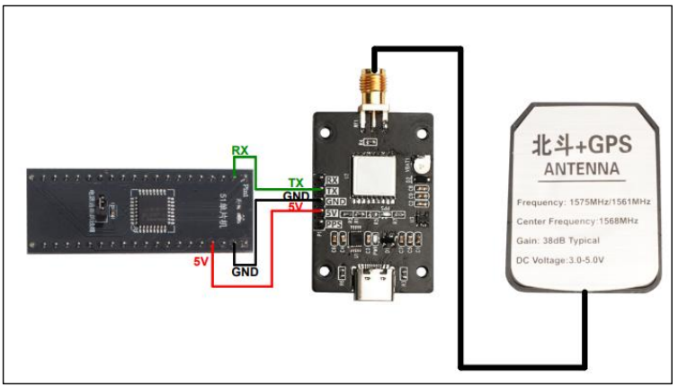
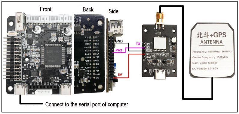
The GPS module supports UART and USB communication, and the UART port of C51 board will be used to retrieve the information. Connect the TX pin to the P3.0 pin of the C51 board, VCC to 5V, and GND to GND. Additionally, connect the STM32 controller to the computer’s USB port using the micro-USB data cable to provide power.
2.1.2 Case Development
In this procedure, the baud rate for serial port printing is set to 9600bps, and the baud rate for the serial port connection between GPS and STC51 is also set to 9600bps.
Initialize the serial port and data array
15 16 17 18 19 20 21 22 23 | void main() { unsigned char i = 0; Uart_Init(); Delay_ms(10); UartPrintf("Welcome to use!"); clrStruct(); |
Read and parse the received data
45 46 47 48 49 50 51 52 53 54 55 56 57 58 59 60 61 62 63 64 65 66 67 68 69 70 71 72 73 74 75 76 77 78 79 80 81 82 83 84 85 86 87 88 89 90 91 92 93 94 | void parseGpsBuffer() { char *subString; char *subStringNext; char i = 0; if (Save_Data.isGetData) { Save_Data.isGetData = false; UartPrintf("**************\r\n"); UartPrintf(Save_Data.GPS_Buffer); for (i = 0 ; i <= 6 ; i++) { if (i == 0) { if ((subString = strstr(Save_Data.GPS_Buffer, ",")) == NULL) errorLog(1); } else { subString++; if ((subStringNext = strstr(subString, ",")) != NULL) { char usefullBuffer[2]; switch(i) { case 1:memcpy(Save_Data.UTCTime, subString, subStringNext - subString);break; case 2:memcpy(usefullBuffer, subString, subStringNext - subString);break; case 3:memcpy(Save_Data.latitude, subString, subStringNext - subString);break; case 4:memcpy(Save_Data.N_S, subString, subStringNext - subString);break; case 5:memcpy(Save_Data.longitude, subString, subStringNext - subString);break; case 6:memcpy(Save_Data.E_W, subString, subStringNext - subString);break; default:break; } subString = subStringNext; Save_Data.isParseData = true; if(usefullBuffer[0] == 'A') Save_Data.isUsefull = true; else if(usefullBuffer[0] == 'V') Save_Data.isUsefull = false; } else { errorLog(2); } } |
Print the received data through serial port
101 102 103 104 105 106 107 108 109 110 111 112 113 114 115 116 117 118 119 120 121 122 123 124 125 126 127 128 129 130 131 132 133 134 135 136 137 | void printGpsBuffer() { if (Save_Data.isParseData) { Save_Data.isParseData = false; UartPrintf("Save_Data.UTCTime = "); UartPrintf(Save_Data.UTCTime); UartPrintf("\r\n"); if(Save_Data.isUsefull) { Save_Data.isUsefull = false; UartPrintf("Save_Data.latitude = "); UartPrintf(Save_Data.latitude); UartPrintf("\r\n"); UartPrintf("Save_Data.N_S = "); UartPrintf(Save_Data.N_S); UartPrintf("\r\n"); UartPrintf("Save_Data.longitude = "); UartPrintf(Save_Data.longitude); UartPrintf("\r\n"); UartPrintf("Save_Data.E_W = "); UartPrintf(Save_Data.E_W); UartPrintf("\r\n"); } else { UartPrintf("GPS DATA is not usefull!\r\n"); } } } |
2.1.3 Program Outcome
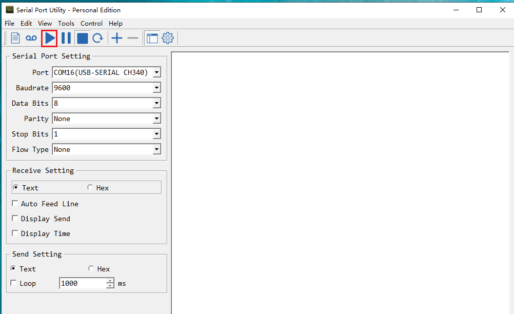
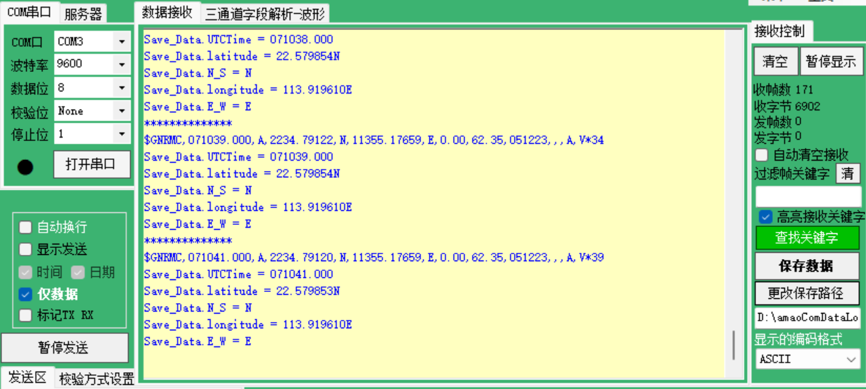
After the module is powered on, it takes approximately 32 seconds to initialize. Subsequently, the serial port printing status light on the module will continuously flash, indicating normal data reception. Once the program is downloaded and executed, open the serial port software and configure the baud rate to 9600. The serial port will then continuously print the current position information in a loop.
Note
For optimal performance, ensure that the module antenna is positioned outdoors. Inadequate signal reception may occur if the antenna is not placed outdoors.
2.2 STM32 Parsing Routine
This procedure utilizes the STM32F103C8T6 chip development board, referred to as STM32 for demonstration purposes. The required equipment includes Win10 or Win11 computers, GPS modules (with pre-wired data interface), micro-USB data cable, CH340 module, and several DuPont cables.
2.2.1 Preparation
The GPS module utilizes UART and USB communication. In this setup, the UART port of the STM32 is employed to retrieve information. Specifically, the module’s TXD is connected to the PA10 pin of the STM32F103C8T6 board, while VCC and GND are connected to the 5V and GND pins of the STM32F103C8T6 board, respectively. Additionally, the GND and RXD of the TTL module are connected to the GND and PA9 pins of the STM32, respectively.
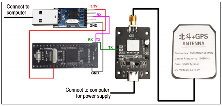
To connect the STM32 to the TTL serial port assistant, you only need to make the following connections:
STM32 GPS
PA10 <—— TXD
STM32USB-TTL module
3.3V ——> 3.3V
GND ——> GND
PA9 ——> RXD
2.2.2 Case Development
In this procedure, the baud rate for serial port printing is set to 9600bps, and the baud rate for the serial port connection between GPS and STM32 is also set to 9600bps.
Initialize the serial port and data array
30 | uart_init(9600); |
Read and parse the received data
53 54 55 56 57 58 59 60 61 62 63 64 65 66 67 68 69 70 71 72 73 74 75 76 77 78 79 80 81 82 83 84 85 86 87 88 89 90 91 92 93 94 95 96 97 98 99 100 101 102 | void parseGpsBuffer() { char *subString; char *subStringNext; char i = 0; if (Save_Data.isGetData) { Save_Data.isGetData = false; printf("**************\r\n"); printf(Save_Data.GPS_Buffer); for (i = 0 ; i <= 6 ; i++) { if (i == 0) { if ((subString = strstr(Save_Data.GPS_Buffer, ",")) == NULL) errorLog(1); } else { subString++; if ((subStringNext = strstr(subString, ",")) != NULL) { char usefullBuffer[2]; switch(i) { case 1:memcpy(Save_Data.UTCTime, subString, subStringNext - subString);break; case 2:memcpy(usefullBuffer, subString, subStringNext - subString);break; case 3:memcpy(Save_Data.latitude, subString, subStringNext - subString);break; case 4:memcpy(Save_Data.N_S, subString, subStringNext - subString);break; case 5:memcpy(Save_Data.longitude, subString, subStringNext - subString);break; case 6:memcpy(Save_Data.E_W, subString, subStringNext - subString);break; default:break; } subString = subStringNext; Save_Data.isParseData = true; if(usefullBuffer[0] == 'A') Save_Data.isUsefull = true; else if(usefullBuffer[0] == 'V') Save_Data.isUsefull = false; } else { errorLog(2); } } |
Convert the latitude and longitude information into degrees
108 109 110 111 112 113 114 115 116 | double Convert_to_degrees(char* data) { double temp_data = atof(data); int degree = (int)(temp_data / 100); double f_degree = (temp_data / 100.0 - degree)*100/60.0; double result = degree + f_degree; return result; } |
Print the received data through serial port
118 119 120 121 122 123 124 125 126 127 128 129 130 131 132 133 134 135 136 137 138 139 140 141 142 143 144 145 146 147 148 149 150 151 152 153 154 155 156 157 158 159 160 161 | void printGpsBuffer() { double f_latitude = 0.0; double f_longitude = 0.0; if (Save_Data.isParseData) { Save_Data.isParseData = false; printf("Save_Data.UTCTime = "); printf(Save_Data.UTCTime); printf("\r\n"); if(Save_Data.isUsefull) { Save_Data.isUsefull = false; printf("Save_Data.latitude = "); // printf(Save_Data.latitude); // printf("--"); f_latitude = Convert_to_degrees(Save_Data.latitude); printf("%lf%s", f_latitude, Save_Data.N_S); printf("\r\n"); printf("Save_Data.N_S = "); printf(Save_Data.N_S); printf("\r\n"); printf("Save_Data.longitude = "); // printf(Save_Data.longitude); // printf("--"); f_longitude = Convert_to_degrees(Save_Data.longitude); printf("%lf%s", f_longitude, Save_Data.E_W); printf("\r\n"); printf("Save_Data.E_W = "); printf(Save_Data.E_W); printf("\r\n"); } else { printf("GPS DATA is not usefull!\r\n"); } } |
2.2.3 Program Outcome
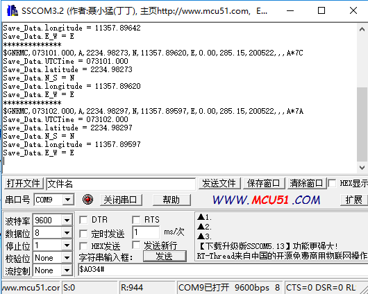
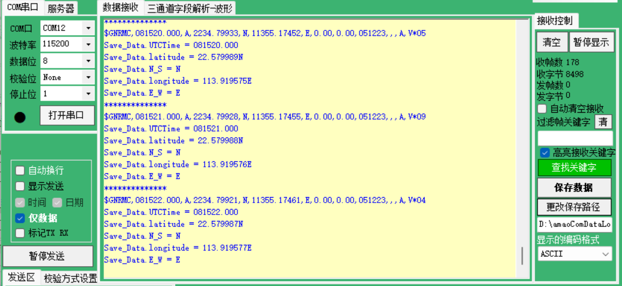
After the module is powered on, it takes approximately 32 seconds to initialize. Subsequently, the serial port printing status light on the module will continue to flash, indicating normal data reception. Once the program is downloaded and executed, open the serial port software, set the baud rate to 9600, and the serial port will continuously print the current location information in a loop.
F103
F407
Note
For optimal performance, ensure that the module antenna is positioned outdoors. Inadequate signal reception may occur if the antenna is not placed outdoors.
2.3 Arduino Reading Routine
This procedure utilizes the Arduino UNO development board, referred to as Arduino for demonstration purposes. The required equipment includes Win10 or Win11 computers, GPS modules (with pre-wired data interface), micro-USB data cables, CH340 modules, and DuPont cables.
2.3.1 Preparation
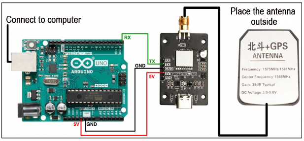
The GPS module utilizes UART and USB communication. In this setup, the UART port of the Arduino UNO is used to read information, with the module’s TX connected to the DO pin of the Arduino UNO board. Additionally, VCC and GND are connected to the 5V and GND pins, respectively, of the Arduino UNO board.
2.3.2 Case Development
Program Analysis
In this procedure, the baud rate for serial port printing is set to 9600bps, and the baud rate for the serial port connection between GPS and Arduino is also set to 9600bps.
(1) Initialize the serial port and data array
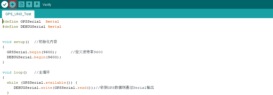
5 6 7 8 9 | void setup() { GPSSerial.begin(9600); DEBUGSerial.begin(9600); } |
(2) Print the received data
11 12 13 14 15 | void loop() { while (GPSSerial.available()) { DEBUGSerial.write(GPSSerial.read()); } |
Compile the Downloaded Program
(1) To compile the program, we require the Arduino IDE software. Open the file using the Arduino IDE, then navigate to the menu bar and click on  . Wait until you see the message “Compilation Successful” appear in the lower left corner.

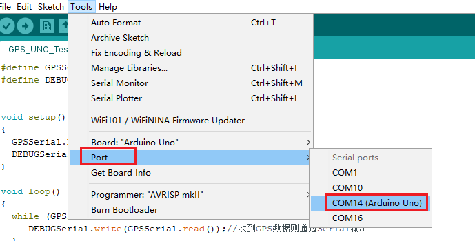
(2) In the menu bar of the Arduino IDE, navigate to [Tools] -> [Port](), and then select the port number that corresponds to the one displayed in the device manager, as illustrated in the following figure:
(3) After selection, click-on  to upload the code to the UNO board. When the programs are uploaded successfully, you will receive the prompt at the lower left corner.
2.3.3 Program Outcome
After the module is powered on, it takes approximately 32 seconds to initialize. Subsequently, the PPS (pulse per second) blue indicator light on the module will continue to flash, indicating normal data reception.
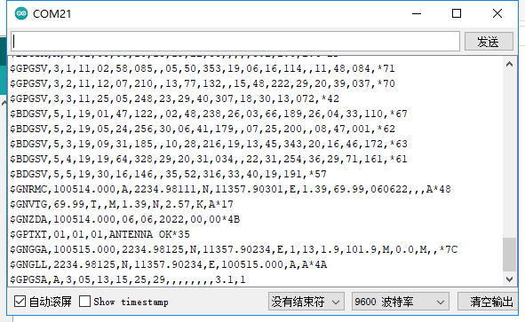
Once the program is downloaded and executed, open the serial port monitoring window and the serial port software. Set the baud rate to 9600. The serial port will then cyclically print the current position information.
It’s important to note that this information is unprocessed original data. For further details, you can refer to the CASIC multi-mode satellite receiver protocol specification document.

Note
For optimal performance, ensure that the module antenna is positioned outdoors. Inadequate signal reception may occur if the antenna is not placed outdoors.
2.4 Arduino Parsing Routine
This procedure utilizes the Arduino UNO development board, which will be referred to as Arduino for convenience. The required equipment includes Win10 or Win11 computers, GPS modules (with pre-wired data interface), micro-USB data cables, CH340 modules, and DuPont cables.
2.4.1 Preparation
The GPS module utilizes UART and USB communication. In this setup, the UART port of the Arduino UNO is used to read information, with the module’s TX connected to the digital output (DO) pin of the Arduino UNO board. Additionally, VCC and GND are connected to the 5V and GND pins, respectively, of the Arduino UNO board.
2.4.2 Case Development
Program Analysis
In this procedure, the baud rate for serial port printing is set to 9600bps, and the baud rate for the serial port connection between GPS and Arduino is also set to 9600bps.
(1) Initialize the serial port and data array
24 25 26 27 28 29 30 31 32 | void setup() { GpsSerial.begin(9600); DebugSerial.begin(9600); Save_Data.isGetData = false; Save_Data.isParseData = false; Save_Data.isUsefull = false; } |
(2) Read the date of serial port
140 141 142 143 144 145 146 147 148 149 150 151 152 153 154 155 156 157 158 159 160 | void gpsRead() { while (GpsSerial.available()) { gpsRxBuffer[ii++] = GpsSerial.read(); if (ii == gpsRxBufferLength)clrGpsRxBuffer(); } char* GPS_BufferHead; char* GPS_BufferTail; if ((GPS_BufferHead = strstr(gpsRxBuffer, "$GPRMC,")) != NULL || (GPS_BufferHead = strstr(gpsRxBuffer, "$GNRMC,")) != NULL ) { if (((GPS_BufferTail = strstr(GPS_BufferHead, "\r\n")) != NULL) && (GPS_BufferTail > GPS_BufferHead)) { memcpy(Save_Data.GPS_Buffer, GPS_BufferHead, GPS_BufferTail - GPS_BufferHead); Save_Data.isGetData = true; clrGpsRxBuffer(); } } } |
(3) Parse the serial port data
84 85 86 87 88 89 90 91 92 93 94 95 96 97 98 99 100 101 102 103 104 105 106 107 108 109 110 111 112 113 114 115 116 117 118 119 120 121 122 123 124 125 126 | void parseGpsBuffer() { char *subString; char *subStringNext; if (Save_Data.isGetData) { Save_Data.isGetData = false; DebugSerial.println("**************"); DebugSerial.println(Save_Data.GPS_Buffer); for (int i = 0 ; i <= 6 ; i++) { if (i == 0) { if ((subString = strstr(Save_Data.GPS_Buffer, ",")) == NULL) errorLog(1); } else { subString++; if ((subStringNext = strstr(subString, ",")) != NULL) { char usefullBuffer[2]; switch(i) { case 1:memcpy(Save_Data.UTCTime, subString, subStringNext - subString);break; case 2:memcpy(usefullBuffer, subString, subStringNext - subString);break; case 3:memcpy(Save_Data.latitude, subString, subStringNext - subString);break; case 4:memcpy(Save_Data.N_S, subString, subStringNext - subString);break; case 5:memcpy(Save_Data.longitude, subString, subStringNext - subString);break; case 6:memcpy(Save_Data.E_W, subString, subStringNext - subString);break; default:break; } subString = subStringNext; Save_Data.isParseData = true; if(usefullBuffer[0] == 'A') Save_Data.isUsefull = true; else if(usefullBuffer[0] == 'V') Save_Data.isUsefull = false; |
(4) Print the parsed position info
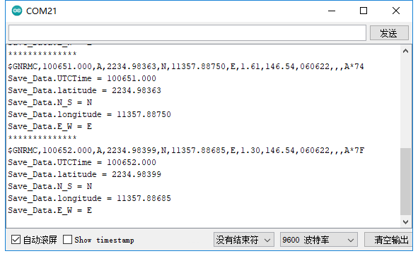
55 56 57 58 59 60 61 62 63 64 65 66 67 68 69 70 71 72 73 74 75 76 77 78 79 80 81 82 | void printGpsBuffer() { if (Save_Data.isParseData) { Save_Data.isParseData = false; DebugSerial.print("Save_Data.UTCTime = "); DebugSerial.println(Save_Data.UTCTime); if(Save_Data.isUsefull) { Save_Data.isUsefull = false; DebugSerial.print("Save_Data.latitude = "); DebugSerial.println(Save_Data.latitude); DebugSerial.print("Save_Data.N_S = "); DebugSerial.println(Save_Data.N_S); DebugSerial.print("Save_Data.longitude = "); DebugSerial.println(Save_Data.longitude); DebugSerial.print("Save_Data.E_W = "); DebugSerial.println(Save_Data.E_W); } else { DebugSerial.println("GPS DATA is not usefull!"); } } } |
(1) Compile the Downloaded Program
① To compile the program, we require the Arduino IDE software. Open the file using the Arduino IDE, then navigate to the menu bar and click on . Wait until you see the message “Compilation Successful” appear in the lower left corner.
② In the menu bar of the Arduino IDE, navigate to [Tools] -> [Port](), and then select the port number that corresponds to the one displayed in the device manager, as illustrated in the following figure:
③ After selection, click-on to upload the code to the UNO board. When the programs are uploaded successfully, you will receive the prompt at the lower left corner.
2.4.3 Program Outcome
After the module is powered on, it takes approximately 32 seconds to initialize. Subsequently, the PPS (pulse per second) blue indicator light on the module will continue to flash, indicating normal data reception.
Once the program is downloaded and executed, open the serial port monitoring window and the serial port software. Set the baud rate to 9600. The serial port will then cyclically print parsed real-time location information.
Note
For optimal performance, ensure that the module antenna is positioned outdoors. Inadequate signal reception may occur if the antenna is not placed outdoors.
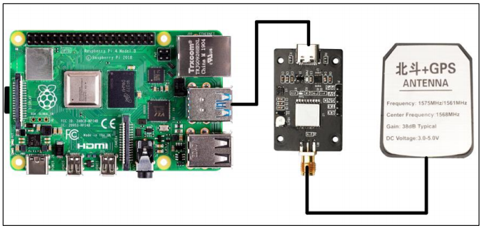
2.5 Raspberry Pi Parsing Routine
This routine utilizes Raspberry Pi and GPS module to read and parse location info.
You need to prepare the following stuffs: Win10 or Win11 computer, IMU module, Type-C data cable and Raspberry Pi development kit.
2.5.1 Preparation
The GPS module supports both UART and USB communication. Here, we’ll use USB communication as an example. As depicted in the figure below, connect the Raspberry Pi and GPS module using a Type-C cable:
Run the command:
ls /dev | grep 'ttyUSB'
you will find that the GPS module is detected as ttyUSB0.
2.5.2 Case Development
In this procedure, the baud rate for serial port printing is set to 9600bps.
Initialize USB
20 | ser = serial.Serial("/dev/ttyUSB0", 9600) |
Retrieve position information and parse function
Extract the position info starting with GNGGA, then parse the data and save them to each global variable.
28 29 30 31 32 33 34 35 36 37 38 39 40 41 42 43 | def Convert_to_degrees(in_data1, in_data2): len_data1 = len(in_data1) str_data2 = "%05d" % int(in_data2) temp_data = int(in_data1) symbol = 1 if temp_data < 0: symbol = -1 degree = int(temp_data / 100.0) str_decimal = str(in_data1[len_data1-2]) + str(in_data1[len_data1-1]) + str(str_data2) f_degree = int(str_decimal)/60.0/100000.0 # print("f_degree:", f_degree) if symbol > 0: result = degree + f_degree else: result = degree - f_degree return result |
46 47 48 49 50 51 52 53 54 55 56 57 58 59 60 61 62 63 64 65 66 67 68 69 70 71 72 73 74 75 76 77 | def GPS_read(): global utctime global lat global ulat global lon global ulon global numSv global msl global cogt global cogm global sog global kph global gps_t if ser.inWaiting(): if ser.read(1) == b'G': if ser.inWaiting(): if ser.read(1) == b'N': if ser.inWaiting(): choice = ser.read(1) if choice == b'G': if ser.inWaiting(): if ser.read(1) == b'G': if ser.inWaiting(): if ser.read(1) == b'A': #utctime = ser.read(7) GGA = ser.read(70) GGA_g = re.findall(r"\w+(?=,)|(?<=,)\w+", str(GGA)) # print(GGA_g) if len(GGA_g) < 13: print("GPS no found") gps_t = 0 return 0 |
Obtain and parse the heading information using the same method
91 92 93 94 95 96 97 98 99 100 101 102 103 104 105 106 107 | elif choice == b'V': if ser.inWaiting(): if ser.read(1) == b'T': if ser.inWaiting(): if ser.read(1) == b'G': if gps_t == 1: VTG = ser.read(40) VTG_g = re.findall(r"\w+(?=,)|(?<=,)\w+", str(VTG)) cogt = VTG_g[0]+'.'+VTG_g[1]+'T' if VTG_g[3] == 'M': cogm = '0.00' sog = VTG_g[4]+'.'+VTG_g[5] kph = VTG_g[7]+'.'+VTG_g[8] elif VTG_g[3] != 'M': cogm = VTG_g[3]+'.'+VTG_g[4] sog = VTG_g[6]+'.'+VTG_g[7] kph = VTG_g[9]+'.'+VTG_g[10] |
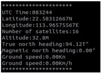
Print the parsed data in a loop
110 111 112 113 114 115 116 117 118 119 120 121 122 123 | try: while True: if GPS_read(): print("*********************") print('UTC Time:'+utctime) print('Latitude:'+lat+ulat) print('Longitude:'+lon+ulon) print('Number of satellites:'+numSv) print('Altitude:'+msl) print('True north heading:'+cogt+'°') print('Magnetic north heading:'+cogm+'°') print('Ground speed:'+sog+'Kn') print('Ground speed:'+kph+'Km/h') print("*********************") |
Run the command to initiate the program
sudo python3 GPS.py
2.5.3 Program Outcome
After the module is powered on, it takes approximately 32 seconds to initialize. Subsequently, the serial port printing status light on the module will continuously flash, indicating normal data reception. Once the program is downloaded and executed, open the serial port software and configure the baud rate to 9600. The serial port will then continuously print the current position information in a loop.
Press Ctrl+C to exit message reading mode.
Note
The antenna must be placed outdoors. Otherwise, the GPS signal cannot be detected, and the terminal will display ‘GPS no found’.
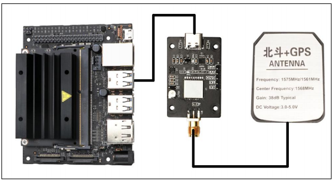
2.6 Jetson Nano Parsing Routine
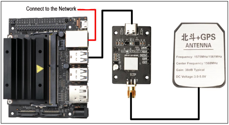
This procedure utilizes the Jetson Nano and GPS module to read and parse the position info. The necessary equipment includes Win10 or Win11 computers, GPS modules, Type-C data cables, and Jetson Nano development kit.
2.6.1 Preparation
The GPS module utilizes either UART communication or USB communication. In this instance, we demonstrate USB communication. Connect the Jetson Nano and the GPS module using a Type-C cable.
Run the command:
ls /dev | grep 'ttyUSB'
and we can found that the GPS module is detected as ttyUSB0.
2.6.2 Case Development
In this procedure, the baud rate for serial port printing is set to 9600bps.
Initialize USB
20 | ser = serial.Serial("/dev/ttyUSB0", 9600) |
Retrieve position information and parse function
Extract the position info starting with GNGGA, then parse the data and save them to each global variable.
28 29 30 31 32 33 34 35 36 37 38 39 40 41 42 43 | def Convert_to_degrees(in_data1, in_data2): len_data1 = len(in_data1) str_data2 = "%05d" % int(in_data2) temp_data = int(in_data1) symbol = 1 if temp_data < 0: symbol = -1 degree = int(temp_data / 100.0) str_decimal = str(in_data1[len_data1-2]) + str(in_data1[len_data1-1]) + str(str_data2) f_degree = int(str_decimal)/60.0/100000.0 # print("f_degree:", f_degree) if symbol > 0: result = degree + f_degree else: result = degree - f_degree return result |
46 47 48 49 50 51 52 53 54 55 56 57 58 59 60 61 62 63 64 65 66 67 68 69 70 71 72 73 74 75 76 77 | def GPS_read(): global utctime global lat global ulat global lon global ulon global numSv global msl global cogt global cogm global sog global kph global gps_t if ser.inWaiting(): if ser.read(1) == b'G': if ser.inWaiting(): if ser.read(1) == b'N': if ser.inWaiting(): choice = ser.read(1) if choice == b'G': if ser.inWaiting(): if ser.read(1) == b'G': if ser.inWaiting(): if ser.read(1) == b'A': #utctime = ser.read(7) GGA = ser.read(70) GGA_g = re.findall(r"\w+(?=,)|(?<=,)\w+", str(GGA)) # print(GGA_g) if len(GGA_g) < 13: print("GPS no found") gps_t = 0 return 0 |
Obtain and parse the heading information of GNVTG using the same method
91 92 93 94 95 96 97 98 99 100 101 102 103 104 105 106 107 | elif choice == b'V': if ser.inWaiting(): if ser.read(1) == b'T': if ser.inWaiting(): if ser.read(1) == b'G': if gps_t == 1: VTG = ser.read(40) VTG_g = re.findall(r"\w+(?=,)|(?<=,)\w+", str(VTG)) cogt = VTG_g[0]+'.'+VTG_g[1]+'T' if VTG_g[3] == 'M': cogm = '0.00' sog = VTG_g[4]+'.'+VTG_g[5] kph = VTG_g[7]+'.'+VTG_g[8] elif VTG_g[3] != 'M': cogm = VTG_g[3]+'.'+VTG_g[4] sog = VTG_g[6]+'.'+VTG_g[7] kph = VTG_g[9]+'.'+VTG_g[10] |
Print the parsed information in a loop
110 111 112 113 114 115 116 117 118 119 120 121 122 123 | try: while True: if GPS_read(): print("*********************") print('UTC Time:'+utctime) print('Latitude:'+lat+ulat) print('Longitude:'+lon+ulon) print('Number of satellites:'+numSv) print('Altitude:'+msl) print('True north heading:'+cogt+'°') print('Magnetic north heading:'+cogm+'°') print('Ground speed:'+sog+'Kn') print('Ground speed:'+kph+'Km/h') print("*********************") |
Execute the command to launch the program
sudo python3 GPS.py
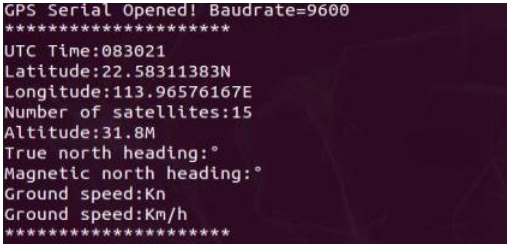
2.6.3 Program Outcome
After the module is powered on, it takes approximately 32 seconds to initialize. Subsequently, the serial port printing status light on the module will continuously flash, indicating normal data reception.
After the program initiates, it begins initializing the USB. If the initialization is successful, it will display “GPS Serial Opened! Baudrate=9600”. Otherwise, it will display “GPS Serial Open Failed!” indicating an error that needs to be investigated. To troubleshoot, please check the cable or USB port. Once resolved, the program will cycle through printing position and heading information.
Press Ctrl+C to exit information reading mode.
Note
The antenna must be placed outdoors. Otherwise, the GPS signal cannot be detected, and the terminal will display ‘GPS no found’.
2.7 ROS Application Routine
2.7.1 Preparation
Note
During compilation, you may encounter the following error: “ImportError: No module named geographiclib.geodesic.” To resolve this, you need to install the corresponding library file using the command:
pip2 install geographiclib.If you encounter compilation times error, you may see the following message: “CMake Error at /opt/ros/melodic/share/catkin/cmake/catkinConfig.cmake:83 (find_package).” To address this, please install the missing
move_base_msgspackage by executing the following commands:
sudo apt-get update
sudo apt-get install ros-melodic-move-base-msgs
When running the program, you might encounter the error: “ImportError: No module named gps_common.msg.” To resolve this issue, execute the following command:
sudo apt-get update
sudo apt-get install ros-melodic-gps-common
GPS Module Compilation Explanation
(1) Use the command to create the workspace.
mkdir gps_ws
(2) After creating the workspace, copy the ‘src’ directory contents of the ‘gps_src’ folder into the workspace directory named ‘gps_ws’.
(3) Then, use ‘catkin_make’ to compile the workspace. If the compilation completes without errors, it passes.
(4) Add source ~/gps_ws/devel/setup.sh to the folder named ~/.zshrc. Execute the command sudo vim ~/.zshrc first,
(5) Then run the command source ~/.zshrc.
(6) Function package content description:
① nmea_navsat_driver: Manages GPS module initialization, reads GPS module data, and handles GPS data visualization.
② nmea_msgs-master: Contains message files storing various GPS messages.
③ imu_gps_localization-master: Implements the fusion of IMU and GPS data for localization purposes.
④ gps_goal: Converts latitude and longitude data into move_base target navigation data.
Bind GPS Port (Optional)
The GPS module is connected to the computer or main controller via the serial port. Therefore, it’s essential to bind the port to the GPS device to avoid recognition issues caused by conflicting port numbers.
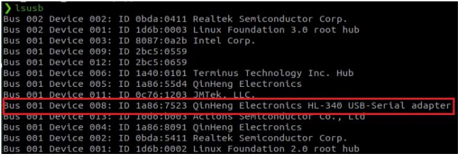
(1) To identify the connected USB device and locate the GPS module, enter ‘lsusb’ in the terminal to find the device’s ID number associated with the GPS module. Refer to the figure below to locate the device identification ID for the GPS module.
lsusb
(2) Once you’ve identified the device number ID, proceed to write the rules file and bind the port. Open the terminal and enter the following commands:
Write the rules file:
sudo vim /etc/udev/rules.d/gps.rules
Copy the following content into the file:
KERNEL=="ttyUSB*", ATTRS{idVendor}=="1a86", ATTRS{idProduct}=="7523", MODE:="0777", SYMLINK+="gps_serial"
Save and exit the file, and give execution permissions:
sudo chmod 777 /etc/udev/rules.d/gps.rules
(3) Replug the GPS module and enter the following command in the terminal to verify if the binding was successful. If you see the expected output on the screen, it indicates that the binding process was successful.
ls -l /dev/gps_serial

Port Distinction (Must Read)
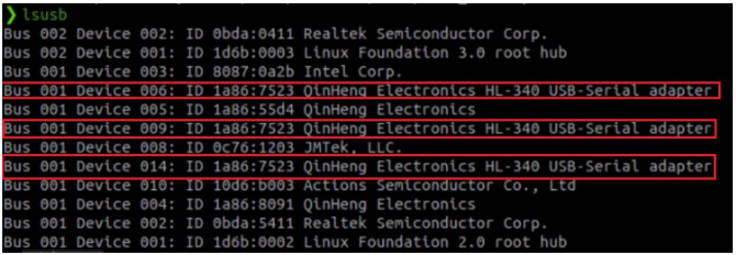
(1) Enter lsusb in the terminal to find multiple device ID numbers. As shown in the figure below, you will notice that the ID numbers of the three devices are the same.
lsusb
(2) Run the command:
ll /dev/ttyUSB*

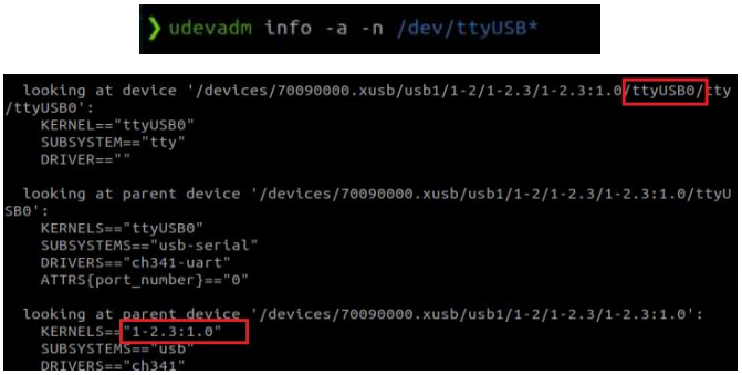
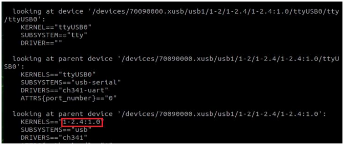
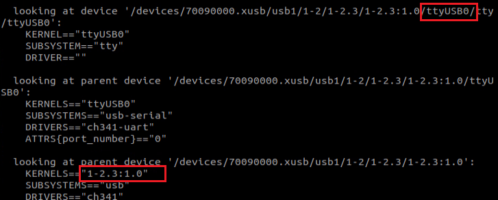
(3) Take note for further differentiation: plug in only the GPS module and execute the command. As illustrated below, you will observe the unique device identification number for the GPS module on this robot, which is “1-2.3:1.0”.
udevadm info -a -n /dev/ttyUSB*
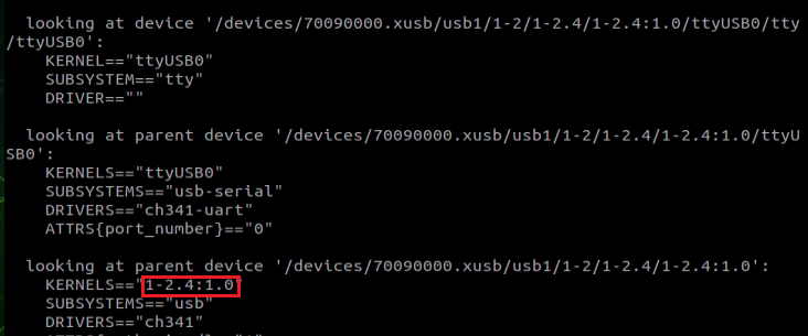
(4) Disconnect the USB cable from the GPS module, insert the USB cable of the Lidar module, and execute the command. You will observe that the unique identifier of the device at this time is “1-2.4:1.0”. Similarly, the newly added module can be identified by querying its unique identification ID.
udevadm info -a -n /dev/ttyUSB*
(5) Include the device identification for differentiation in the ‘gps.rules’ file. Enter the command and add the following content to the document:
sudo vim /etc/udev/rules.d/gps.rules
SUBSYSTEM=="tty",KERNELS=="1-2.1.2:1.0",MODE:="0777",
SYMLINK+="gps_serial"

(6) Include the device identification for differentiation in the ‘lidar.rules’ file. Enter the command and add the following content to the document:
sudo vim /etc/udev/rules.d/lidar.rules
SUBSYSTEM=="tty", KERNELS=="1-2.1.4:1.0",MODE:="0777", SYMLINK+="lidar"

The newly added module can be configured using the same method.
(7) Save the changes and close the file. Then, grant execution permission to the file. Execute the following two commands in the terminal:
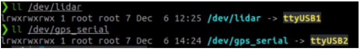
sudo chmod 777 /dev/gps_serial
sudo chmod 777 /dev/lidar
(8) After making the modifications, execute the command to update the .rules file. Then, reload it to verify the changes.
sudo udevadm control --reload-rules
(9) Reconnect the USB cable of all modules to verify:
Unplug the GPS module to verify:
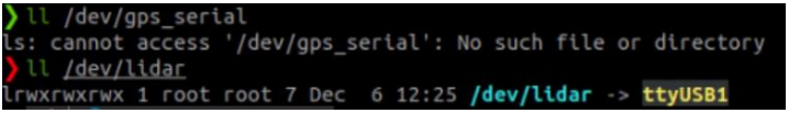
After verifying the changes, proceed to the following steps.
2.7.2 Read the Data of GPS Module
This function is designed to retrieve GPS module data via the terminal and analyze it to extract longitude, latitude, and altitude information.
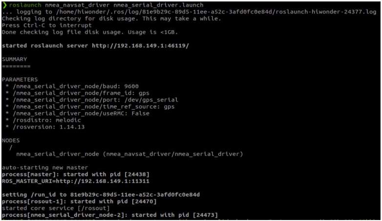
Read GPS Data via Terminal
Run the following command on the terminal.
roslaunch nmea_navsat_driver nmea_serial_driver.launch
Next, we examine the topic data by entering the following command in the terminal.
rostopic list

| Topic | Type | Description |
|---|---|---|
| /extend fix | gps_common/GPSFix | GPSFix messages include GPS satellite status and positioning information |
| /fix | sensor_msgs/NavSatFix | GPS localization information |
| /time reference | sensor_msgs/TimeReferencd | GPS time information |
| /vel | geometry_msgs/TwistStamped | GPS speed information |
Regarding the data on the GPS topics, here is an explanation:
For each topic message type, please refer to the official documentation at the following website addresses:
gps_common/GPSFix Documentation (ros.org)
sensor_msgs/NavSatFix Documentation (ros.org)
sensor_msgs/TimeReference Documentation (ros.org)
geometry_msgs/TwistStamped Documentation (ros.org)
To print out these topic messages in the terminal and obtain GPS data, take the ‘print /fix’ topic as an example. Enter:
rostopic echo /fix
The terminal will display the following data:
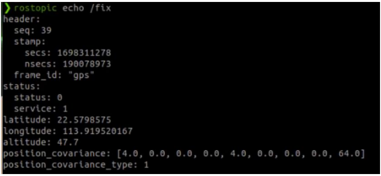
Among them, latitude, longitude, and altitude represent latitude, longitude, and altitude, respectively.
Read Latitude, Longitude and Altitude of GPS
Run the following command on the terminal:
roslaunch nmea_navsat_driver nmea_serial_driver.launch
rosrun nmea_navsat_driver read_lat_long.py
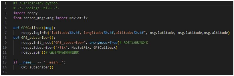
The data printed by the terminal represents the longitude, latitude, and altitude of the current GPS module. Please review the source code in read_lat_long.py for further details.
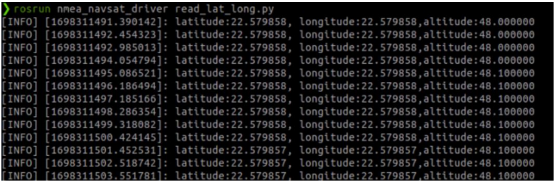
The program subscribes to the data from the /fix topic, processes it within the callback function, and ultimately prints the parsed data to the terminal.
2.7.3 Draw GPS Trajectory
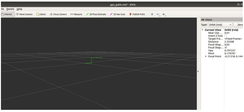
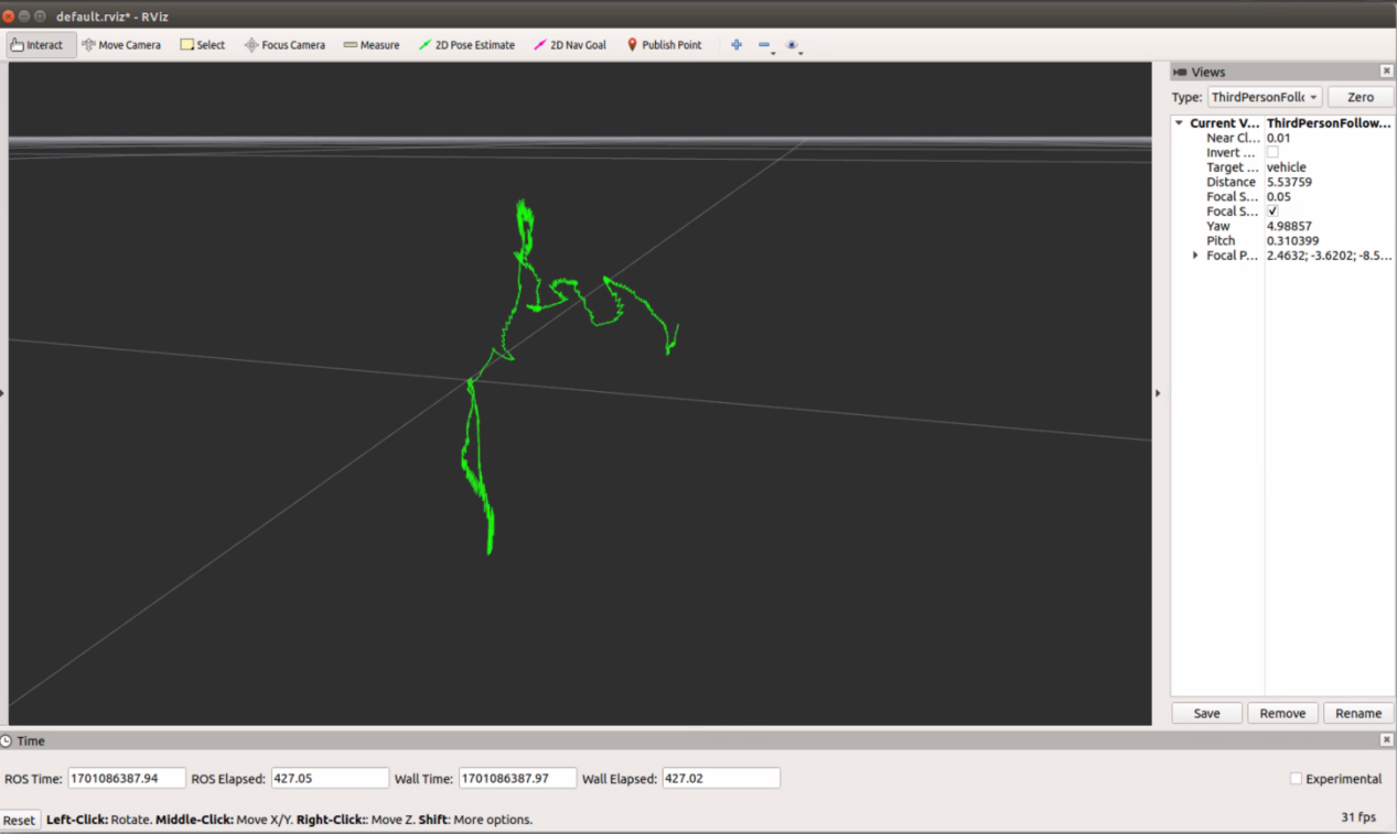
This function visualizes real-time GPS data and displays it in RViz.
Program Logic
It is not possible to directly visualize GPS information. We need to convert the coordinate system from longitude and latitude WGS-84 coordinates to the real-world XYZ coordinate system. With XYZ coordinates in the real world, we can use RViz to display the path and simulate the GPS trajectory. To create the trajectory, we accumulate the position of each GPS coordinate relative to the first coordinate, resulting in the trajectory.
Startup Instructions
Execute the command:
roslaunch nmea_navsat_driver gps_path_to_rviz.launch
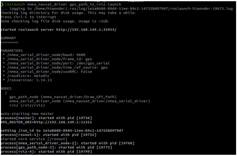
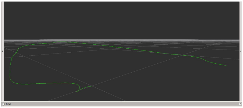
In the RViz interface, you can observe a slowly extending green line, as depicted in the figure below.
launch Code Analysis
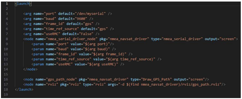
Three nodes are launched: nmea_serial_driver_node to read GPS data, gps_path_node to plot GPS data tracks, and rviz nodes for visualization.
The source code for the gps_path_node, namely GPS_Path.cpp, can be found in nmea_navsat_driver/src directory. Feel free to review it at your convenience.
2.7.4 Integration of imu and GPS
This function combines IMU and GPS data and presents the fused data in RViz.
IMU and GPS Data Fusion Operation
Copy the ‘gps.bag’ from the course directory to the ‘/home’ directory. This data package is intended for demonstration purposes only. In the terminal, enter:
roslaunch imu_gps_localization imu_gps_localization.launch
rosbag play gps.bag
Once executed, as the data packet is played, the green trajectory in RViz will continue to extend, representing the fused position.
In this instance, we utilize the data package within the folder for demonstration purposes. However, during actual development, it’s essential to employ the rosbag tool to record IMU and GPS data. You can examine the contents of this data packet by executing:
rosbag info gps.bag
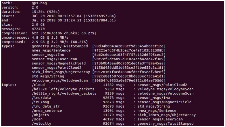
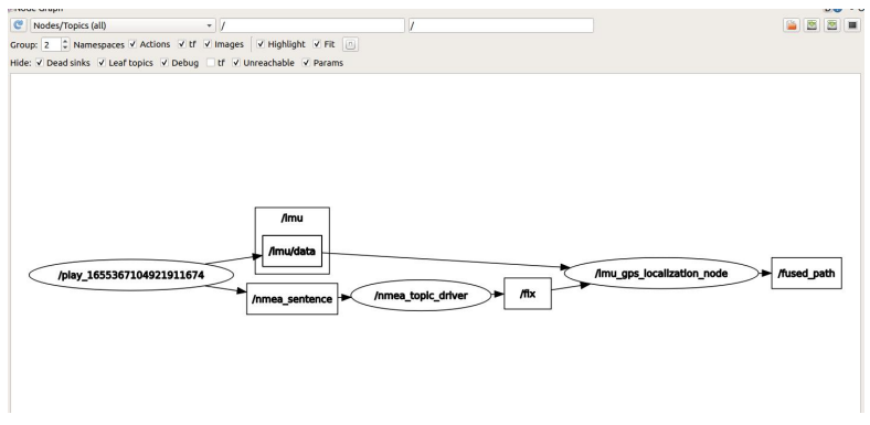
The topic section of this data packet comprises recorded topics, notably including IMU (/imu/data and /imu/mag) and GPS (/nmea_sentence) data. Throughout operation, we can visualize the node graph to observe topic transmission among nodes. You can do so by entering the following into the terminal.
rosrun rqt_graph rqt_graph
launch File
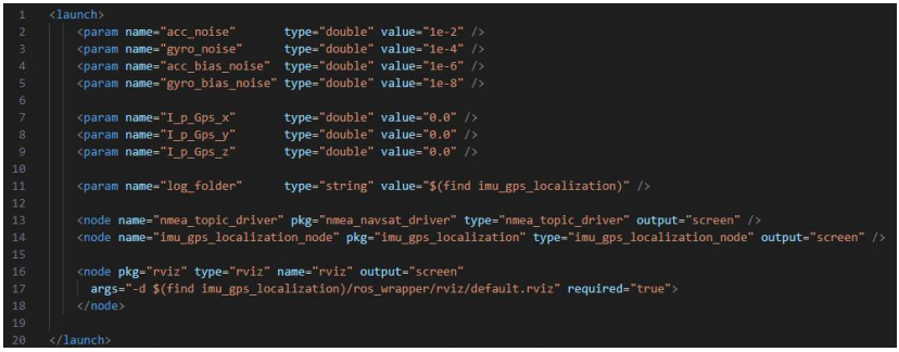
The imu_gps_localization_node plays a crucial role in integrating IMU and GPS data. Its source code resides in imu_gps_localization-master/ros_wrapper/src, with particular attention to localization_wrapper.cpp. This file manages topic subscription, data fusion, and publication. If you’re inclined, you’re welcome to explore it further.
Integrate IMU and GPS Data
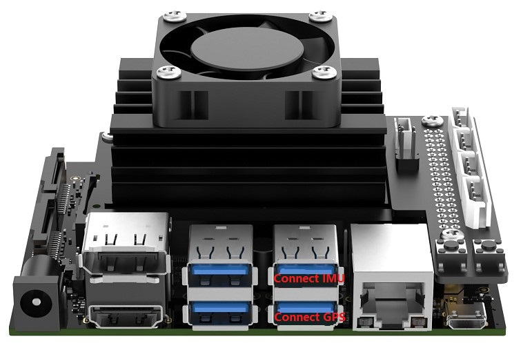
(1) Module Connection
This example uses the Jetson Nano as the controller. If you are using a PC virtual machine or a Raspberry Pi, you will need to check and adjust the corresponding device identifier numbers accordingly.
(2) Port Identification
① First, import the gps_ws and imu_ws packages onto the Jetson Nano desktop.
② Open the terminal and enter the command lsusb to list connected USB devices and find the GPS and IMU modules’ device IDs.
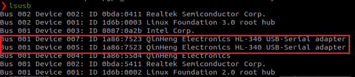
③ As shown in the figure below, you may see that both modules share the same device ID. To distinguish them, you will use the USB bus address of each device. Start by connecting only the IMU module, then run command “udevadm info -a -n /dev/ttyUSB*”. You will see a unique identifier for the IMU module, “1-2.3:1.0” in this example.
udevadm info -a -n /dev/ttyUSB*
④ Next, disconnect the IMU and connect the GPS module. Run the same command again: udevadm info -a -n /dev/ttyUSB* You should now see a different unique identifier, such as “1-2.4:1.0”.
udevadm info -a -n /dev/ttyUSB*
⑤ Add device identification rules in the imu_usb.rules file. Enter the command “sudo vim /etc/udev/rules.d/imu_usb.rules” to edit the file. Then, enter the following content into the file:
SUBSYSTEM=="tty", KERNELS=="1-2.3:1.0", MODE:="0666",
SYMLINK+="imu_usb"

⑥ Add device identification rules in the gps.rules file. Enter the command “sudo vim /etc/udev/rules.d/gps.rules” to edit the file. Then, enter the following content into the file:
SUBSYSTEM=="tty", KERNELS=="1-2.4:1.0", MODE:="0666",
SYMLINK+="gps_serial"

⑦ After making the changes, enter the following two commands to reload the udev rules and trigger the devices to be re-recognized:
sudo udevadm control --reload-rules
sudo udevadm trigger
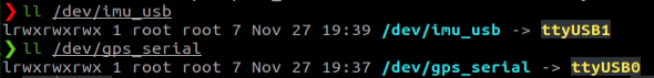
Connect both the IMU and GPS modules to verify:
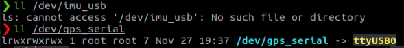
Unplug the IMU module to verify:
Once everything is verified to be working correctly, proceed with the following steps.
(3) Compile the Workspace
① Place both gps_ws and imu_ws workspaces in your home directory. Then, navigate to each workspace and compile using the following command:
catkin_make
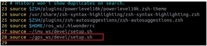
② After compilation, add the following lines to your ~/.zshrc file:
source ~/imu_ws/devel/setup.sh
source ~/gps_ws/devel/setup.sh
③ Finally, refresh the environment variables: source ~/.zshrc
(4) IMU and GPS Data Fusion
This section demonstrates how to fuse IMU and GPS data, and visualize the result in RViz. Important Notes:
① Make sure both the IMU and GPS modules are connected to the controller via two separate data cables.
② Two separate workspaces are required: gps_ws and imu_ws. Their source folders (gps_src and imu_src) are located in the current directory. After extracting gps_src, copy the contents inside its src folder into the src folder of gps_ws, then run catkin_make to compile. Similarly, after extracting imu_src, copy its src contents into the src folder of imu_ws, and compile it using catkin_make. You can refer to the gps_ws and imu_ws workspaces provided in the virtual machine for reference.
③ The default baud rate for both IMU and GPS modules is 9600. Data fusion requires data from two topics: /imu/data and /fix. These topics can be obtained by launching the IMU and GPS modules. To start the fusion process, run the following command: roslaunch imu_gps_localization imu_gps_test.launch
④ After launching, you may initially see a warning indicating that there’s not enough IMU data. Just wait a few moments — the warning will disappear, and soon you’ll see the fused path being printed. An example of the output is shown below:
⑤ The launch file includes the following components:
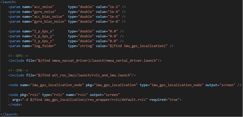
nmea_serial_driver.launch: Retrieves GPS data and publishes it to the /fix topic. rviz_and_imu.launch: Retrieves IMU data and publishes it to the /imu/data topic. imu_gps_localization_node: Subscribes to both /fix and /imu/data, performs the fusion process, and publishes the result to the /fused_path topic. You can check the list of active topics with rostopic list, or visualize the node connections using rosrun rqt_graph rqt_graph. A diagram of the topic relationships is shown below:

2.7.5 GPS and move_base Navigation
Note
If you encounter the error “ImportError: No module named geographiclib.geodesic” when executing the command, you will need to install the corresponding library file using the command: pip2 install geographiclib.
If you intend to specify a longitude and latitude and then utilize Move_Base for navigation to that point, directly inputting the target point is not feasible. Consequently, the longitude and latitude coordinates must be converted into xy data for the Move_Base target point. This section elucidates the process of implementing this data conversion.
Startup
Before initiating, ensure that move_base is successfully activated and that a blank map is imported. It is crucial to verify that the longitude and latitude coordinates of the desired point are within the boundaries of the map. Otherwise, the program may issue a warning stating, “The goal sent to the navfn planner is off the global costmap. Planning will always fail to this goal,” indicating that the path planning cannot reach the specified location.
(1) The demonstration provided here utilizes our robot’s image. Please enter the command:
roslaunch hiwonder_navigation navigation.launch map:=map_01

(2) Execute the command to view the navigation effect using rviz:
roslaunch hiwonder_navigation rviz_navigation.launch
(3) Run the move_base program, then input the command on the terminal:
roslaunch gps_goal gps_goal.launch
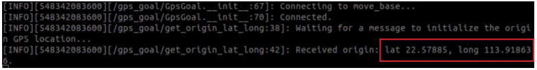
(4) Given the initial location longitude and latitude, enter the following command in the command terminal:
rostopic pub /local_xy_origin geometry_msgs/PoseStamped '{ header: { frame_id: "/map" }, pose: { position: { x: 22.578850, y: 113.918636 } } }' -1
Here, a message is published to the topic named /local_xy_origin. The data following consist of reference values for x and y, which must be assigned based on the actual scenario. Upon execution, the terminal will display “Received origin: lat -79.379, long 43.658”.
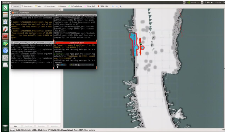
(5) Given the location longitude and latitude of the target point, enter the following command in the command terminal:
rostopic pub /gps_goal_fix sensor_msgs/NavSatFix "{latitude: 22.578850, longitude: 113.918640}" -1
① The data published to the /gps_goal_fix topic message is provided here. The latitude and longitude data within are for reference purposes only, and their values should be adjusted according to the specific circumstances. Upon execution, the terminal will display the following message:

② Upon printing the message, it is evident that the calculated distance between the two points is 0.411 meters (owing to the significant disparity in longitude and latitude provided), with an azimuth angle of 90 degrees. Subsequent conversion yields the coordinates (5.51315297, 0.41135133), representing the xy value of the target point on the map within move_base. However, this value notably exceeds the map’s scope, rendering path planning impossible to reach this point. As previously mentioned, it’s imperative to ensure that the longitude and latitude of both origin and target points fall within the map boundaries. Following the calculation of xy values, the data is packaged and transmitted to move_base for path planning. The image below illustrates the outcome:
Program Source Code gps_goal.py
path: workspace src/gps_goal/src/gps_goal/gps_goal.py
The code is simple and we can directly check cli_main function.
143 144 145 146 147 | gpsGoal = GpsGoal(); # Check for degrees, minutes, seconds format and convert to decimal lat, long = DMS_to_decimal_format(lat, long) gpsGoal.do_gps_goal(lat, long, roll=roll, pitch=pitch, yaw=yaw) |
do_gps_goal Function
78 79 80 81 82 83 84 | def do_gps_goal(self, goal_lat, goal_long, z=0, yaw=0, roll=0, pitch=0): # Calculate goal x and y in the frame_id given the frame's origin GPS and a goal GPS location x, y = calc_goal(self.origin_lat, self.origin_long, goal_lat, goal_long) print("Goal x: ",x) print("Goal y: ",y) # Create move_base goal self.publish_goal(x=x, y=y, z=z, yaw=yaw, roll=roll, pitch=pitch) |
The calc_goal function computes the xy value using the longitude and latitude of the origin, along with those of the target point.
The publish_goal function encapsulates the xy value into MoveBaseGoal() type data and transmits it.
2.8 AGNSS Assistant Localization
Leverage Jetson Nano, the GPS module, and an AGNSS server to attain position reading and parsing, particularly in conditions of weak signal.
2.8.1 AGNSS Description
Why do we use AGNSS:
(1) The prerequisites for autonomous GNSS receiver positioning entail:
① Acquiring and tracking satellite signals while resolving time
② Receiving messages from satellites
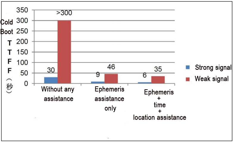
(2) In robust signal conditions, an autonomous GNSS receiver can accomplish cold-start positioning within approximately 30 seconds. Conversely, in environments with weak signals, a receiver lacking external assistance struggles to capture satellites promptly and obtain satellite messages. Consequently, positioning in such conditions is prolonged and may even fail to occur.
(3) AGNSS plays a pivotal role by furnishing the receiver with essential auxiliary information for positioning, including messages, approximate position, and time. Whether operating in strong or weak signal environments, this information substantially reduces the time required for initial positioning.
AGNSS Solution
(1) The AGNSS server acquires and oversees AGNSS assistance information sourced from various GNSS data outlets. Continuously monitoring, it promptly responds to client AGNSS requests, which necessitate username and password authentication.
(2) Users retrieve auxiliary information from the AGNSS server via the TCP/IP protocol. This auxiliary data can be directly relayed to the GNSS receiver.
(3) Users also have the option to establish their own proxy servers.
AGNSS Request Parameter
(1) The client forwards a request to the AGNSS server in the following format:
The request statement comprises multiple groups of key=value pairs, structured as: key=value; key=value;
(2) Example:
user=pm@hiwonder.com; pwd=hiwonder; cmd=full; gnss=gps+bd; lat=60.0; lon=55.0; alt=0;
(3) The key and value definitions are outlined as follows:
| Keyword | Value | Mandatory/ Optional | Note |
|---|---|---|---|
| User | Character string | Mandatory | Username: It is strongly recommended that the username be a valid email address, as important AGNSS server maintenance information will be sent to it. |
| pwd | Character string | Mandatory | User password |
| gnss | Character string | Optional | A comma-separated list of currently supported GNSS for GPS.Valid values include: gps, bds, glo."gnss=gps;" signifies a request for GPS assistance information."gnss=gps,bds;" indicates a request for GPS and BDS assistance information.Additional Information; |
| cmd | Character string | Optional | Options for requested information:"full": Full information, encompassing ephemeris, estimated time, and location."eph": Provides solely ephemeris information."aid": Includes auxiliary time, location, and other relevant data.If left unspecified, the default option is "full" |
| at | value | Optional | An estimation of the user's latitude. Single latitude bit, measured in degrees. Valid range: -90° to 90°. Auxiliary format for both longitude and latitude, either in high position format or ECEF format. Valid format for latitude and longitude high position auxiliary is "lat=30; lon=120.3; alt=100;". All three fields must be complete. |
| pacc | value | Optional | User position estimated in the ECEF coordinate system. Unit: meters. Valid ECEF location auxiliary format is "x=30000; y=1111120.3; z=3345100;". All fields must be complete. |
| user | value | Optional | Estimated user position in the ECEF coordinate system, measured in meters. |
| pwd | value | Optional | Estimated user position in the ECEF coordinate system, measured in meters. |
| gnss | Character string | Optional | Estimated user position accuracy, measured in meters. |
Server Returns Information
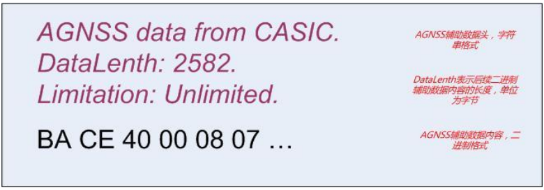
(1) An example of data returned by the AGNSS server comprises a data header followed by auxiliary data content.
(2) Binary data, essential for GNSS receivers, includes data verification and adheres to the receiver protocol specification provided by Zhongke Micro.
(3) Transmitting the data header alongside the auxiliary data to the GNSS receiver does not affect its functionality.
Comparison Between AGNSS Performance
Precautions
(1) Rough position assistance requires users to obtain it through alternative means, such as:
GSM/GPRS/3G communication modules, which can utilize CELL ID to acquire current rough positions.
Other wireless modules like WiFi can also provide rough positioning.
(2) The accuracy requirement for rough positions is within 15km. Erroneous position assistance can impact the receiver’s performance.
(3) If unable to obtain rough positions, omit the position fields (lat, lon, alt, x, y, z) in the AGNSS request statement. The receiver will automatically select valid positions from historical data.
(4) It is unnecessary to use positions outputted by the GNSS receiver itself as rough positions.
When do We Need AGNSS
(1) It’s unnecessary to download from the server every time the device boots up, conserving data usage.
The icofchina chips have built-in battery-backed SRAM and permanent backup FLASH, capable of automatically storing received ephemeris data.
During regular operation, the chip continuously downloads the latest ephemeris data from satellites.
(2) Determine whether to download AGNSS data from the server by querying the receiver’s status.
The receiver can output status messages (disabled by default, configuration required for activation).
Introduction to Message Status Statements
Example:
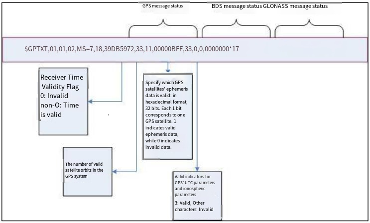
$GPTXT, 01,01,02, MS = 7,18,39 DB5972, 33,11,00000 BFF, 33,0,00000000 * 17
7: Time validity sign.
0 is invalid, 2 is an external input, and 7 is valid. 18: The number of valid GPS satellites in the ephemeris.
39DB5972: GPS satellite ephemeris valid marker (unsigned integer, hexadecimal display). Each satellite occupies one position, with the lowest position being Satellite 1, and so on. 1 indicates valid, 0 indicates invalid.
33: GPS UTC and ION information valid flag (unsigned short integer, hexadecimal display.) The first digit is the UTC information valid flag, and the second digit is the I0N information valid flag.
11: The number of BDS satellites valid in the ephemeris. 3 indicates valid, 2 indicates expired, 1 indicates unhealthy, and 0 indicates invalid.
00000BFF: BDS satellite ephemeris valid marker (unsigned integer, hexadecimal display). Each satellite occupies one position, with the lowest position being Satellite 1, and so on. 1 indicates valid, 0 indicates invalid.
33: The UTC and ION information of BDS is valid. The information regulation is the same as the UTC and ION information validity markers of GPS.
0: The number of valid GLN satellites in the ephemeris.
00000000: Valid marker for GLN satellite ephemeris. Consistent with the valid marker of the GPS satellite ephemeris.
(1) This statement outputs the current time and message status within the receiver.
(2) You can send the command $PCAS03,,,,,,,,,,,1*1F to output message status statements every second.
(3) Sending the command $PCAS03,,,,,,,,,,,0*1E stops the output of message status statements.
(4) Note: Each statement must end with \r\n (0x0D,0x0A), and the statement contains 11 commas.
(5) If the time flag is valid (non-zero) and there are many valid ephemerides (more than 8), there is no need to download AGNSS ephemerides.
2.8.2 Wiring Preparation
The GPS module utilizes UART or USB communication. Here, USB communication is exemplified. Connect the Jetson Nano (or Raspberry Pi) and the GPS module using a Type-C cable.
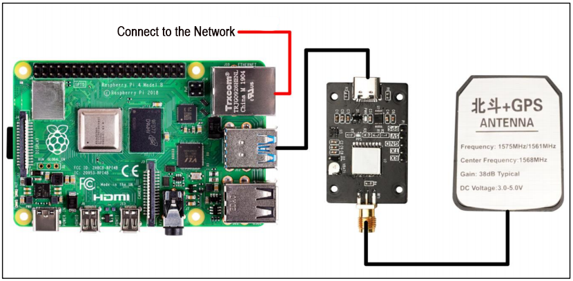
Run the command:
ls /dev | grep 'ttyUSB'
It can be seen that the GPS module is recognized as USB0.
