4. Offline Speech Function
4.1 Function Overview
4.1.1 Common Concept Explanation
Note
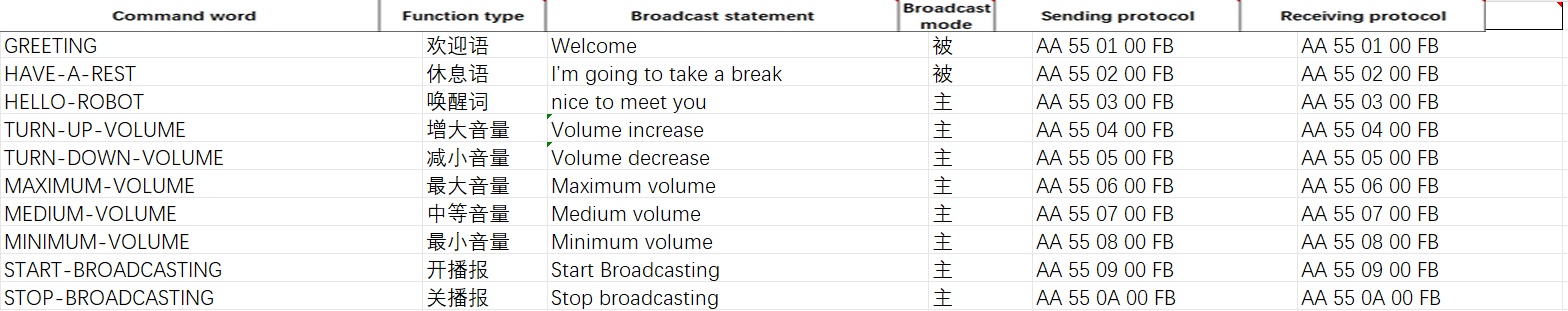
For a better understanding, it is recommended to study the “Command Word Broadcast Protocol List” file in “Appendix/05 Command Word Broadcast Protocol List”.
For detailed explanations of the “Command Word Broadcast Protocol List”, please refer to 4.10 Command Word Broadcast Speech ID Analysis.
In WonderLLM’s offline speech function, three types of entries can be processed: (1) Functional entries (2) Command word type entries (3) Broadcast word type entries.
Functional entries and Command word type entries can be recognized by the module’s offline speech feature. When the entry is spoken, the module can recognize it on its own. Functional entries are recognized by the module, which then executes the corresponding underlying functions, such as adjusting the module’s broadcast volume. Command word type entries are recognized by the module, and the recognition result can be read by an external controller for custom operations.
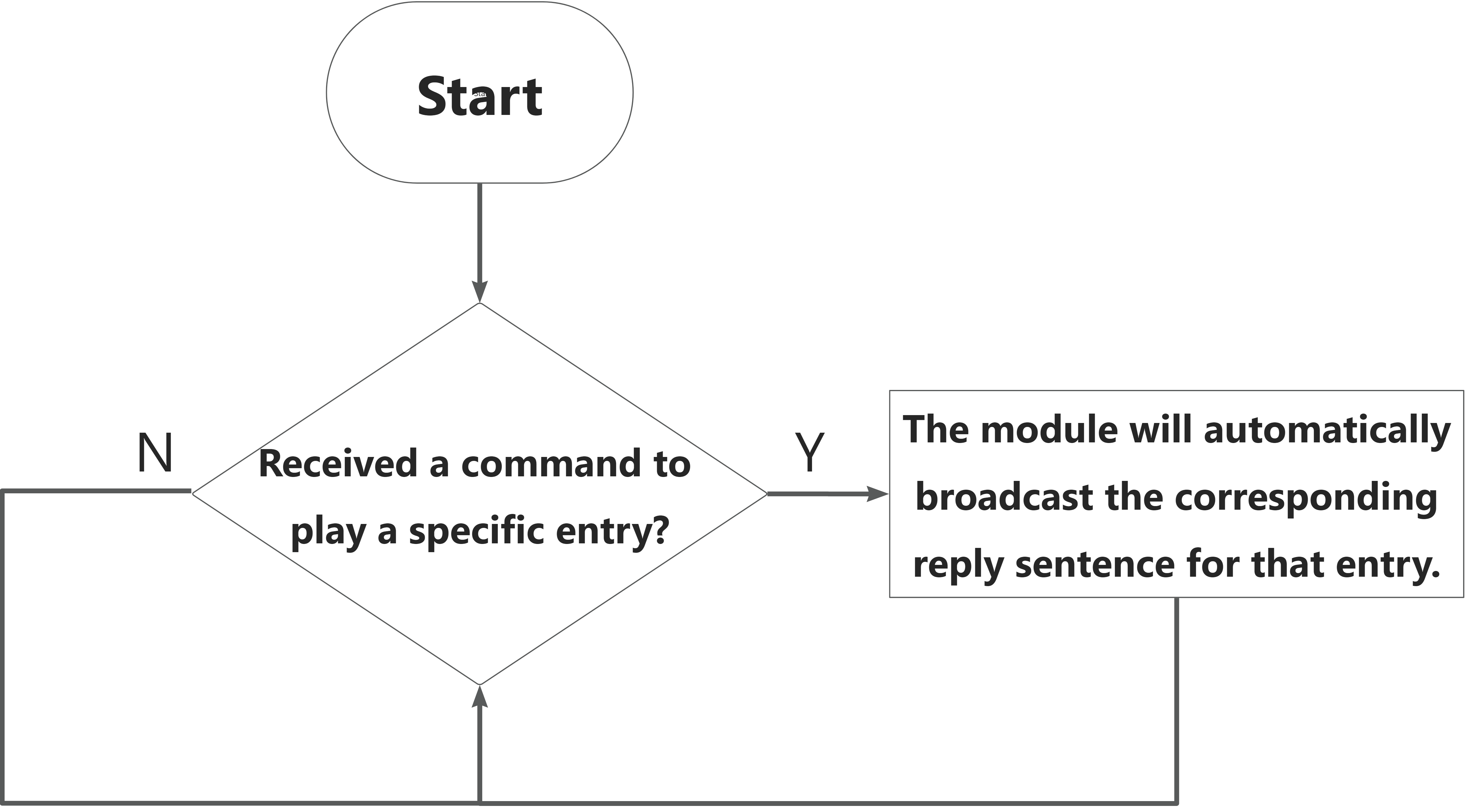
Broadcast word type entries cannot be recognized by the module’s speech recognition system. They are used to trigger one of the entries under this category by an external controller. Upon receiving the command, the module will broadcast the corresponding response statement.
All entries can have a broadcast type, divided into: (1) Active broadcast (2) Passive broadcast.
Note
If active broadcast is selected, the entry will be recognized by the module after being spoken, and the corresponding response statement will be broadcast automatically. If passive broadcast is selected, the corresponding response statement can only be triggered by a command sent from an external controller.
Broadcast word type entries are not supported by the module’s speech recognition and can only be set to “passive broadcast.”
Entries that support “active broadcast” also support “passive broadcast” by default, but the reverse is not true.
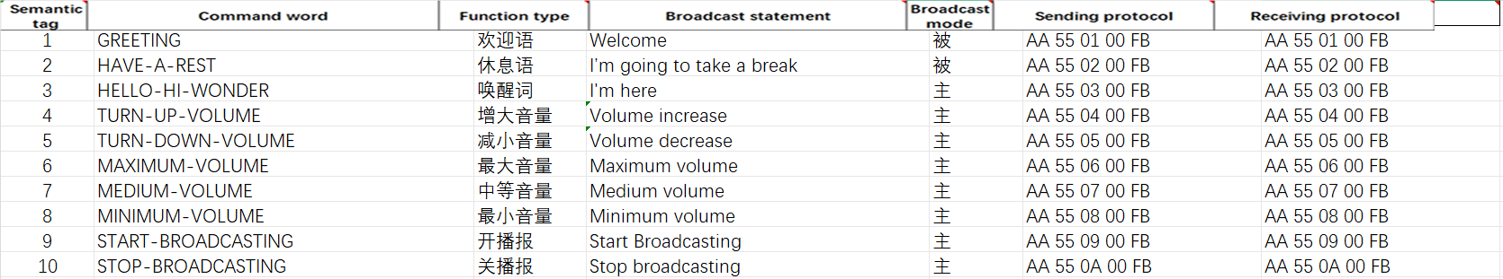
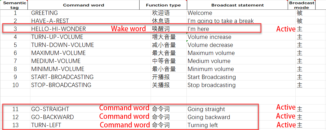
Functional entries include: (1) Welcome message (2) Rest message (3) Wake word (4) Increase volume (5) Decrease volume (6) Maximum volume (7) Medium volume (8) Minimum volume (9) Turn on broadcast (10) Turn off broadcast.
Note
The above 10 functional entries correspond to entries 1-10 in the “Command Word Protocol List” file.
(!!Important) Functional entries are only used to adjust the module’s operation. The speech recognition results for these entries cannot be queried, but they can control the module to broadcast the corresponding response statement.
“Welcome message” is the entry that the module automatically broadcasts after power-on. “Rest message” is the entry that the module broadcasts automatically when it enters sleep mode after not detecting any valid entries for a long time. In the factory firmware, these two entries are set to passive broadcast by default.
“Wake word” is used to activate the module, exit sleep mode, and start actively recognizing “functional entries” and “command word type entries.”
If the “Turn off broadcast” type entry is issued, entries with “active broadcast” will no longer automatically broadcast the corresponding response statement once recognized by the module. The effect of “Turn on broadcast” works in the opposite way.
4.1.2 Communication Structure and Functional Division
The WonderLLM module integrates the CI1302 speech chip and the ESP32S3 controller. The ESP32S3 controller can unidirectionally receive serial data from the CI1302, which refers to the entry recognition results.
In the offline speech function, both components are responsible for different parts of the speech interaction functions, as shown in the diagram below:
Note
If there is a need to develop custom entries, refer to this diagram to understand the category of the entries that need modification, as well as the chips involved in implementing the functions of each entry, in order to create the corresponding firmware for the chips.
4.1.3 Module Usage Process
Note
Before using the module’s offline speech function, refer to 4.2 Firmware Flashing Tutorial to flash the CI1302 firmware and the ESP32S3 firmware for the module.
Functional entries / Command word type entries
Speech Recognition Workflow
External Controller Communication Process
Broadcast word type entries
External Controller Communication Process
4.2 Firmware Flashing Tutorial
Note
This section uses the factory firmware as an example to explain how to flash the CI1302 firmware and ESP32S3 firmware to the WonderLLM module, enabling the module to run the offline speech function.
4.2.1 CI1302 Firmware Flashing
First, connect the Type-C interface at the bottom of the WonderLLM module to the computer using a USB data cable.

Open the “Appendix/01 CI1302 Firmware Flashing Tool” path and run the PACK_UPDATE_TOOL.exe file. Select the CI1302 chip and then click Firmware Upgrade.
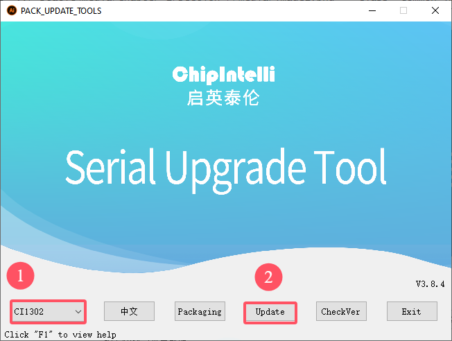
Note
This example uses flashing the English firmware (wake word: hello hiwonder).
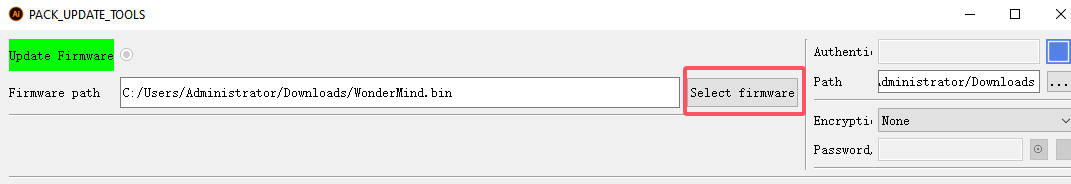
Click Select firmware, and find the CI1302 factory firmware in the “Appendix/02 CI1302 Factory Firmware” path.
Locate the appropriate serial port and click to select it.
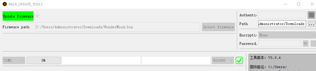
Then press both the left and right buttons on the WonderLLM module simultaneously to begin the flashing process. Wait for the flashing to complete successfully.


Wake Word Test
After flashing the firmware, restart the module and wait for it to complete network configuration. Once it enters the expression interface, say the new wake word. If the module’s buzzer sounds once and the module enters the chat interface, replying with a greeting, this indicates the wake word modification was successful.
4.2.2 ESP32S3 Firmware Flashing
Device Connection
Connect the WonderLLM model module’s Type-C interface to the computer using a USB cable, as shown in the image below.

Operation Process
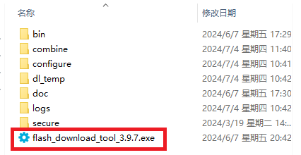
Please open the “Appendix/04 ESP32 Firmware Flashing Tool/flash_download_tool_3.9.7” path and run the flash_download_tool_3.9.7.exe file.
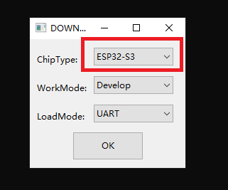
Select ESP32-S3 as the Chip Type, leave the other settings as default, and then click OK.
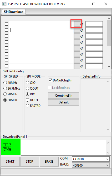
After opening the tool, click “…” to select the program bin file to be flashed which stored in the path: “Appendix/03 ESP32S3 Firmware”.

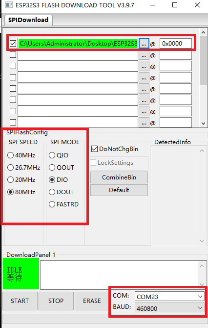
On the left side, check the box, and configure the remaining settings as shown in the diagram. Select the COM port number corresponding to the module’s assigned port.
Note
If the SPI MODE is set to DIO as shown in the diagram, the module may not function properly after flashing. Please try setting the SPI MODE to DOUT and flashing the firmware again.
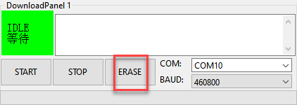
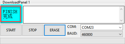
First, click ERASE to erase the previously downloaded firmware. This step is necessary! Then wait for the status bar to display FINISH.
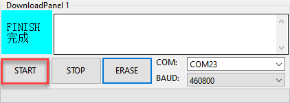
Click START to download the newly selected firmware. Wait for the progress bar to complete, and the firmware download will be finished.
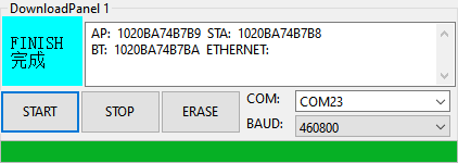
After the download is complete, unplug and reconnect the data cable. Once the device powers on again, it will start operating according to the new firmware program.
4.3 Modify Wake Words
The CI1302 factory firmware provided by Hiwonder has a self-learning feature, allowing it to learn the custom wake word based on the existing firmware, thus eliminating the hassle of creating a new firmware version.
Note
The “modify wake word” explained in this section does not mean creating a completely new wake word. From a functional perspective, it is about giving an alias to an existing wake word.
If it is necessary to modify a custom wake word while creating the firmware, refer to 4.8.1 CI1302 Firmware Creation.
4.3.1 Notice
Modify the wake word in a quiet environment, as noisy surroundings may affect the recognition accuracy of the WonderLLM module.
When speaking the entry, ensure the voice is loud and the speech rate is not too fast. It is recommended to maintain a distance of no more than 5 meters from the module.
4.3.2 Device Connection
Power the WonderLLM module through either of its two Type-C ports or the 4-pin interface.
4.3.3 How to Modify Wake Words
Say Hello Hiwonder to the WonderLLM module to wake it up. When the module replies I am here, it indicates that the module is in a recognizable state.
Then say Study wake word to the WonderLLM module, and the module will respond with Please say wake command, indicating that it has entered the wake word learning mode.
Next, say the desired wake word to the WonderLLM module. The wake word should be as short as possible. Here, set Hiwonder as an example.
When the WonderLLM module successfully recognizes the wake word, it will broadcast Learning succeed, indicating that the wake word has been modified successfully and supports power-off saving. At this point, either Hello Hiwonder or Hiwonder can be used to wake up the module.
Note
The wake word “hello Hiwonder” in the factory firmware is the default wake word and cannot be modified or deleted via voice. The wake word modified by voice will coexist with the default wake word.
After learning a custom wake word, if a new custom wake word is learned, it will overwrite the old one.
4.4 Modify Command Words
The CI1302 factory firmware provided by Hiwonder has a self-learning feature, allowing it to learn the custom command word based on the existing firmware, thus eliminating the hassle of creating a new firmware version.
Note
The “modify command word” explained in this section does not mean creating a completely new command word. From a functional perspective, it is about giving an alias to an existing command word.
For example, the default command word “forward” can be modified by learning an alias “move forward” for the command word “forward”. After successful learning, say “move forward”, the module will broadcast the response statement corresponding to “forward”. The external controller will read the recognition result sensor and obtain the result for “forward”.
Not every command word supports learning an alias through the “modify command word” function. This feature is determined during firmware creation. The entries that support the “modify command word” function in the factory firmware will be introduced later.
If it is necessary to modify a custom command word while creating the firmware”, refer to 4.8.1 CI1302 Firmware Creation.
4.4.1 Notice
Modify the command word in a quiet environment, as noisy surroundings may affect the recognition accuracy of the WonderLLM module.
When speaking the entry, ensure the voice is loud and the speech rate is not too fast. It is recommended to maintain a distance of no more than 5 meters from the module.
4.4.2 Device Connection
Power the WonderLLM module through either of its two Type-C ports or the 4-pin interface.
4.4.3 How to Modify Command Words
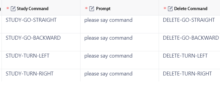
The WonderLLM module’s factory firmware predefines 4 command words that can be modified via voice, as shown below:
Usage example is as follows:
(1) Say Hello Hiwonder to the WonderLLM module to wake it up. When the module replies I am here, it indicates that the module is in a recognizable state.
Note
The wake word for the English version of the factory firmware is “Hello Hiwonder”. When the module is woken up, it replies with “I’m here”.
(2) Then say Study go straight to the WonderLLM module, and the module will respond with Please say the command, indicating that it has entered the command word learning mode.
(3) Next, say the desired command word to the WonderLLM module. The command word should be as short as possible. Here, set go forward as an example.
(4) When the WonderLLM module successfully recognizes the command, it will broadcast Learning succeed, indicating that the command word has been modified successfully. At this point, using the Go forward entry will have the same effect as the Go straight command word.
(5) If it is necessary to delete the Go forward entry, simply say Delete go straight. Only go forward will be deleted, not go straight.
Note
The command words such as “go straight” in the factory firmware are default command words and cannot be modified or deleted via voice. The command words modified by voice can only coexist with one default command word, both existing simultaneously.
If an alias for a command word is learned using the “Study command word” function, and then another alias is learned for the same command word, the new alias will overwrite the old one.
4.5 Modify Functional Entries
4.5.1 CI1302 Firmware Modification Preparation
In the “Appendix/05 Command Word Broadcast Word Protocol List/01 Command Word Protocol List” path, find the corresponding “Command Word Broadcast Word Protocol List” for the factory firmware. Copy it to another location for backup, and changes will be made on the backup file.
Note
Do not make direct changes to the original file to avoid irreversible errors.
Locate the functional entries in the table, which are the first 10 items. The first 10 functional entries are fixed and cannot be added. Only modifications are supported.
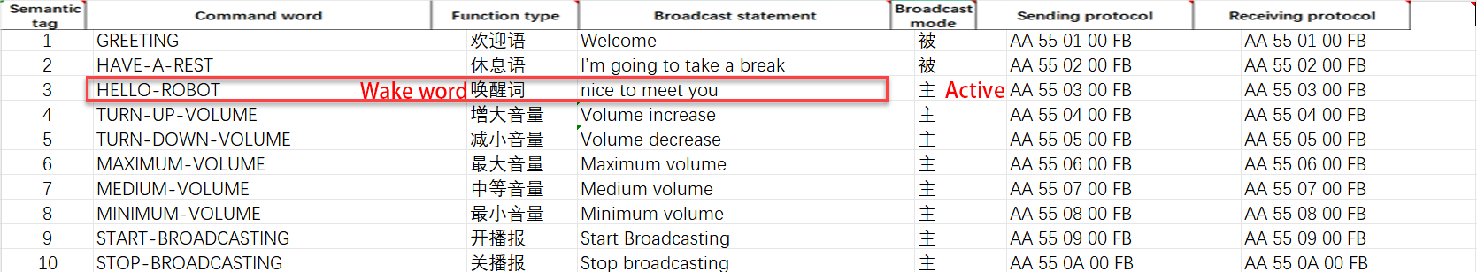
Taking modifying the wake word as an example, after saying hello robot, the module will be activated and automatically broadcast the response statement nice to meet you, as shown in the diagram below:
Note
In the “Command Word Broadcast Word Protocol List,” all entries (including command words, broadcast words, and functional entries) under the “Command Word” column must be written entirely in uppercase letters and use hyphens (-) to separate multiple words.
The “Broadcast Statement” column for the entries does not have the above requirements, and lowercase letters can be used.
Save the modified backup of the Command Word Broadcast Word Protocol List file. Then follow the steps in 4.8.1 CI1302 Firmware Creation to import the table into the website to create the CI1302 firmware. If the firmware has already been created once, click the Inherit button in the previous project to skip the parameter configuration step.

After recreating the firmware, refer to 4.2.1 CI1302 Firmware Flashing to flash the firmware to the WonderLLM module.
Note
After flashing the CI1302 firmware, the voice recognition and active broadcast functions for the entry are successfully modified. Next, proceed to create the ESP32S3 firmware to adapt the passive broadcast functionality for the new entry.
4.5.2 ESP32S3 Firmware Modification Preparation
In the “Appendix/05 Command Word Broadcast Word Protocol List/02 Broadcast Word Protocol List” path, find the Broadcast Word V3_English_Template corresponding to the factory firmware. Copy it to another location for backup. All subsequent changes will be made to this backup file. Open the backup file.
Note
Do not make direct changes to the original file to avoid irreversible errors.
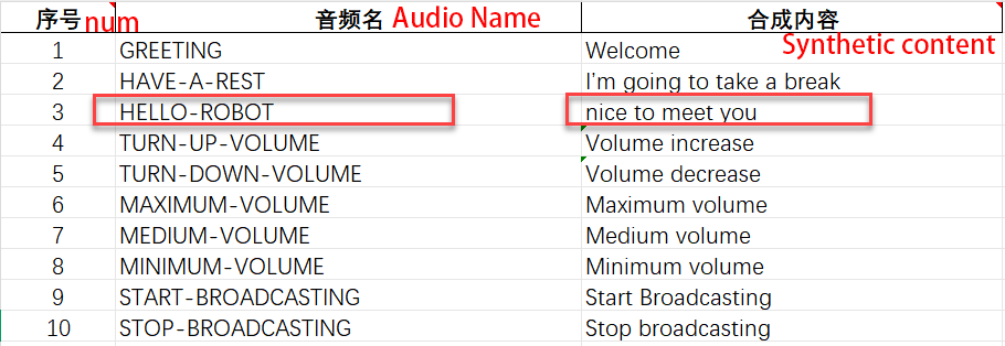
In this table, there are three columns: Serial Number, Audio Name, and Synthesis Content, which correspond to the Semantic Label, Command Word, and Broadcast Statement columns in the Command Word Broadcast Word Protocol List file located in “Appendix/05 Command Word Broadcast Word Protocol List/01 Command Word Protocol List”.
In this table, find the row where the Serial Number corresponds to the Semantic Label of the wake word in the Command Word Broadcast Word Protocol List, and then modify the Audio Name and Synthesis Content accordingly.
Save the modified backup of the Broadcast Word V3_English Template file. Then, follow the steps in 4.8.2 ESP32S3 Firmware Creation to import the table into the website to create the entry audio, which will later be used for passive broadcast playback by the external controller.
After recreating the firmware, refer to 4.2.2 ESP32S3 Firmware Flashing to flash the firmware to the WonderLLM module.
Note
After flashing the ESP32S3 firmware, the passive broadcast function for the entry is successfully modified.
4.6 Add New Command Entries
4.6.1 CI1302 Firmware Modification Preparation
In the “Appendix/05 Command Word Broadcast Word Protocol List/01 Command Word Protocol List” path, find the corresponding “Command Word Broadcast Word Protocol List” for the factory firmware. Copy it to another location for backup, and changes will be made on the backup file.
Note
Do not make direct changes to the original file to avoid irreversible errors.
At the end of the table for all command-type entries, add a new row and fill in the custom content. For example, when saying start patrol, the module will be activated and automatically broadcast the response statement OK, I will inspect the surrounding area, as shown in the diagram below:
Note
In the “Command Word Broadcast Word Protocol List,” all entries (including command words, broadcast words, and functional entries) under the “Command Word” column must be written entirely in uppercase letters and use hyphens (-) to separate multiple words.
The “Broadcast Statement” column for the entries does not have the above requirements, and lowercase letters can be used.
In the “Command Word Broadcast Word Protocol List” file, each entry (including functional entries, command word entries, and broadcast word entries) has a unique semantic label. A semantic label can be assigned to a new entry, but it is necessary to check the table to ensure there is no conflict with any existing entries. It is recommended to set the new entry’s semantic label as the “previous entry’s semantic label + 1”.
For the new entry, set the function type to “Command Word”. The broadcast mode can be freely chosen, with the default setting as “Active” (Active Broadcast).
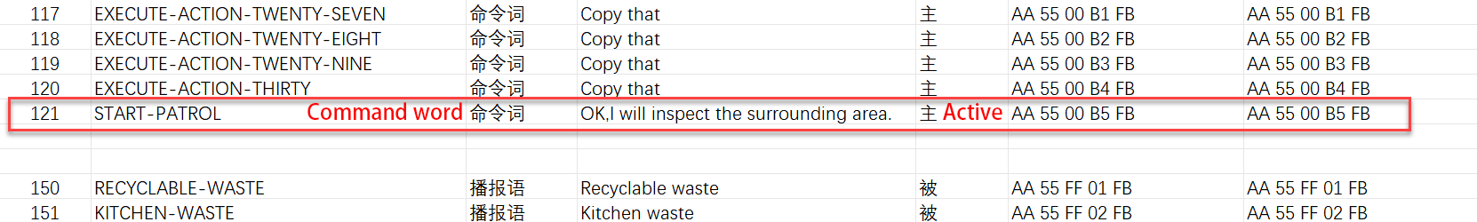
Then, fill in the transmission and reception protocols for the new entry. The transmission and reception protocols for the same command word are the same. The first two bytes should be the fixed frame header AA 55, the third byte should be the command word type value 00, the fourth byte should be the 1-byte ID of the new entry (recommended to be “previous command word ID + 1”), and the fifth byte should be the fixed frame tail FB.
Note
The transmission and reception protocols for all command word type entries, except for the 4th byte, are identical. The transmission and reception protocols of other command word type entries can be copied and pasted into the new entry row.
The 4th byte in the transmission and reception protocols of command word type entries represents the unique ID for each command word (range: 01–FF). Each command word entry ID must be unique. Assign any ID to the new entry, but check the table to ensure there are no conflicts with other command words.
In the “Command Word Broadcast Word Protocol List” file provided by Hiwonder, the IDs for command word type entries are arranged in ascending order from top to bottom. It is recommended to set the new entry ID as “previous command word ID + 1”.
Additionally, existing command word type entries in the table can also be modified. Simply modify the “Command Word” and “Broadcast Statement” of the existing entry. This is more efficient and saves the allocation of entry IDs.
Save the modified backup of the Command Word Broadcast Word Protocol List file. Then follow the steps in 4.8.1 CI1302 Firmware Creation to import the table into the website to create the CI1302 firmware. If the firmware has already been created once, click the Inherit button in the previous project to skip the parameter configuration step.
After recreating the firmware, refer to 4.2.1 CI1302 Firmware Flashing to flash the firmware to the WonderLLM module.
Note
After flashing the CI1302 firmware, the voice recognition and active broadcast functions for the entry are successfully modified. Next, proceed to create the ESP32S3 firmware to adapt the passive broadcast functionality for the new entry.
4.6.2 ESP32S3 Firmware Modification Preparation
In the “Appendix/05 Command Word Broadcast Word Protocol List/02 Broadcast Word Protocol List” path, find the Broadcast Word V3_English Template corresponding to the factory firmware. Copy it to another location for backup. All subsequent modifications will be made to this backup file. Open the backup file to proceed.
Note
Do not make direct changes to the original file to avoid irreversible errors.
In this table, there are three columns: Serial Number, Audio Name, and Synthesis Content, which correspond to the Semantic Label, Command Word, and Broadcast Statement columns in the Command Word Broadcast Word Protocol List file located in “Appendix/05 Command Word Broadcast Word Protocol List/01 Command Word Protocol List”.
In this table, find the row where the Serial Number corresponds to the Semantic Label of the newly added/modified command word in the Command Word Broadcast Word Protocol List, and then update the Audio Name and Synthesis Content accordingly.

Save the modified backup of the Broadcast Word V3_English Template file. Then, follow the steps in 4.8.2 ESP32S3 Firmware Creation to import the table into the website to create the entry audio, which will later be used for passive broadcast playback by the external controller.
After recreating the firmware, refer to 4.2.2 ESP32S3 Firmware Flashing to flash the firmware to the WonderLLM module.
Note
After flashing the ESP32S3 firmware, the passive broadcast function for the entry is successfully modified.
4.7 Add Broadcast Words
4.7.1 Modify Command Word Broadcast Word Protocol List
Note
As explained in 4.1.2 Communication Structure and Functional Division, since the broadcast words are fully controlled and implemented by the ESP32S3 firmware, there is no need to modify or adapt the CI1302 firmware when adding new broadcast words.
The purpose of this section in the “Command Word Broadcast Word Protocol List” is to: ① facilitate understanding of subsequent operations, ② fully correspond to the latest module features.
In the “Appendix/05 Command Word Broadcast Word Protocol List/01 Command Word Protocol List” path, find the corresponding “Command Word Broadcast Word Protocol List” for the factory firmware. Copy it to another location for backup, and changes will be made on the backup file.
Note
Do not make direct changes to the original file to avoid irreversible errors.
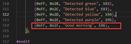
At the end of the table for all broadcast word entries, add a new row and fill in the custom content, as shown in the diagram below:
Note
In the “Command Word Broadcast Word Protocol List,” all entries (including command words, broadcast words, and functional entries) under the “Command Word” column must be written entirely in uppercase letters and use hyphens (-) to separate multiple words.
The “Broadcast Statement” column for the entries does not have the above requirements, and lowercase letters can be used.
The content in the “Command Word” column for broadcast words can be freely filled in based on the above spelling requirements. It is recommended to fill in the “Command Word” of the new entry as the “broadcast content” converted into uppercase with words separated, as shown in the diagram below.
In the “Command Word Broadcast Word Protocol List” file, each entry (including functional entries, command word entries, and broadcast word entries) has a unique semantic label. A semantic label can be assigned to a new entry, but it is necessary to check the table to ensure there is no conflict with any existing entries. It is recommended to set the new entry’s semantic label as the “previous entry’s semantic label + 1”.
For the new entry, set the function type to “Broadcast Word”; the broadcast mode must be set to “Passive” (Passive Broadcast).
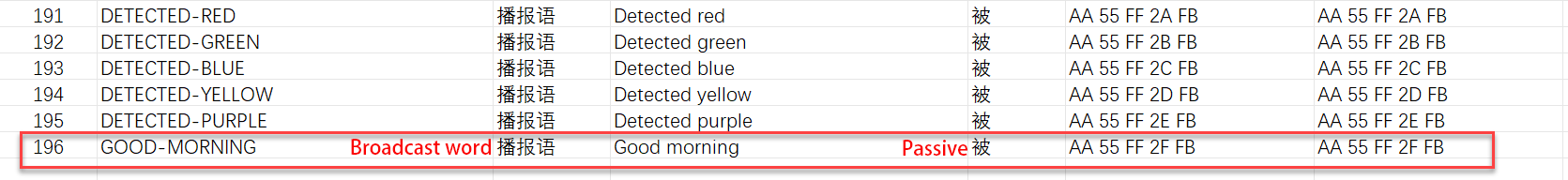
Then fill in the transmission and reception protocols for the new entry. The transmission and reception protocols for the same broadcast word are the same. The first two bytes should be the fixed frame header AA 55, the third byte should be the command word type value FF, the fourth byte should be the 1-byte ID of the new entry (recommended to be “previous broadcast word ID + 1”), and the fifth byte should be the fixed frame tail FB.
Note
The transmission and reception protocols for all broadcast word type entries, except for the 4th byte, are identical. The transmission and reception protocols of other broadcast word type entries can be copied and pasted into the new entry row.
The 4th byte in the transmission and reception protocols of broadcast word type entries represents the unique ID for each broadcast word (range: 01–FF). Each broadcast word entry ID must be unique. Assign any ID to the new entry, but it is necessary to check the table to ensure there is no conflict with other broadcast words.
In the “Command Word Broadcast Word Protocol List” file provided by Hiwonder, the IDs for broadcast word type entries are arranged in ascending order from top to bottom. It is recommended to set the new entry ID as “previous broadcast word ID + 1”.
Additionally, existing broadcast word type entries in the table can also be modified. Simply modify the “Command Word” and “Broadcast Statement” of the existing entry. This is more efficient and saves the allocation of entry IDs.
Save the modified backup Command Word Broadcast Word Protocol List file.
Note
Next, proceed to create the ESP32S3 firmware to adapt the passive broadcast functionality for the new entry.
4.7.2 ESP32S3 Firmware Creation
In the “Appendix/05 Command Word Broadcast Word Protocol List/02 Broadcast Word Protocol List” path, find the Broadcast Word V3_English_Template corresponding to the factory firmware. Copy it to another directory as a backup. All subsequent modifications will be made to this backup file. Open the backup file to proceed.
Note
Do not make direct changes to the original file to avoid irreversible errors.
In this table, there are three columns: Serial Number, Audio Name, and Synthesis Content, which correspond to the Semantic Label, Command Word, and Broadcast Statement columns in the Command Word Broadcast Word Protocol List file located in “Appendix/05 Command Word Broadcast Word Protocol List/01 Command Word Protocol List”.
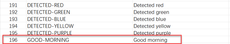
At the end of the table for all broadcast word entries, add a new row and fill in the custom content. The Serial Number should correspond to the Semantic Label of the new entry in the Command Word Broadcast Word Protocol List; the Audio Name should be the Command Word from the Command Word Broadcast Word Protocol List; the Synthesis Content should be the Broadcast Statement from the Command Word Broadcast Word Protocol List, as shown in the diagram below:
Note
If any broadcast word is modified in the “Command Word Broadcast Word Protocol List,” it must also be updated here.
Save the modified backup of the Broadcast Word V3_English Template file. Then, follow the steps in 4.8.2 ESP32S3 Firmware Creation to import the table into the website to create the entry audio.
After recreating the firmware, refer to 4.2.2 ESP32S3 Firmware Flashing to flash the firmware to the WonderLLM module.
Note
After flashing the ESP32S3 firmware, the passive broadcast function for the entry is successfully modified.
4.8 Firmware Creation Tutorial
Note
The CI1302 firmware has a self-learning feature, allowing certain personalized needs to be implemented based on the original firmware without the need to create a new one. > It is recommended to first complete 4.3 Modify Wake Words, 4.4 Modify Command Words, 4.5 Modify Functional Entries, 4.6 Add New Command Entries, and 4.7 Add Broadcast Words sections.
The following case demonstrates adding a command word entry and a broadcast word entry, as well as modifying commonly used wake words in functional entries, based on the original functionality of the factory firmware.
Before starting this section, please complete the study of 4.1.2 Communication Structure and Functional Division to understand the types of entries requiring modification based on requirements, as well as the chips involved in the implementation of each function, thereby facilitating the planning of corresponding firmware creation.
4.8.1 CI1302 Firmware Creation
First, open the link to the “Chipintelli Voice AI Platform” to access the firmware creation official website.
Click the Platform Functions. Then click on Deep development of product firmware and SDK under the Product Development section.

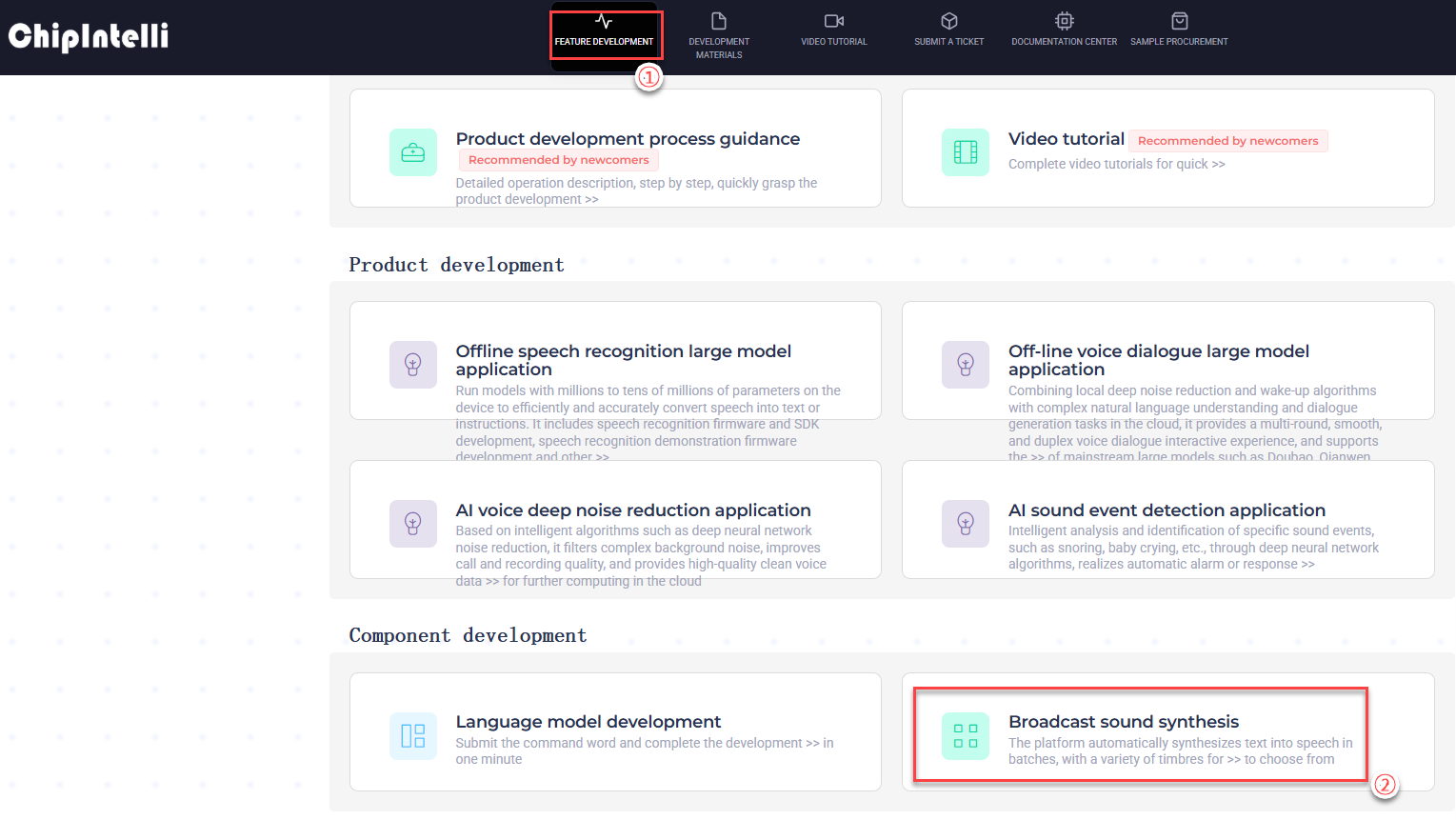
The system will prompt for a login. If registration is not completed, complete the platform account registration first. In this example, registration has already been completed. After successfully logging in, click on FEATURE DEVELOPMENT first.
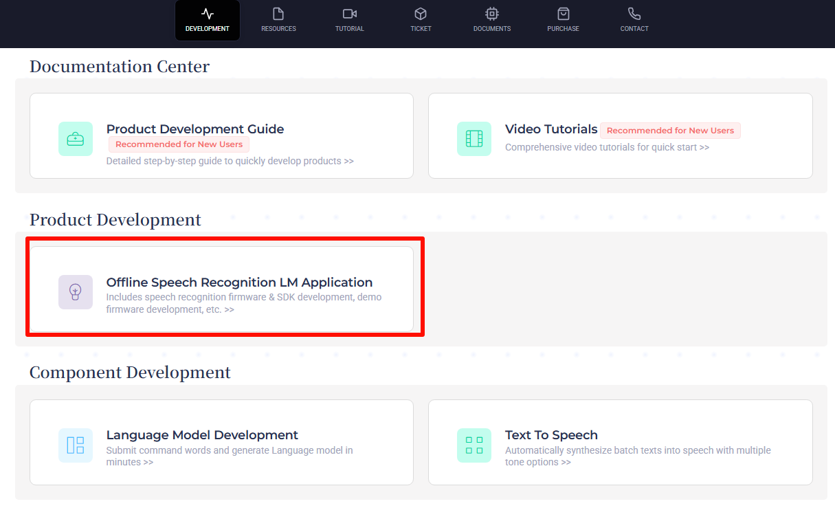
In the submenu, click the Offline speech recognition large model application entry.

After the page redirects, click on
 on the left. Then create a new product as shown in the below image.
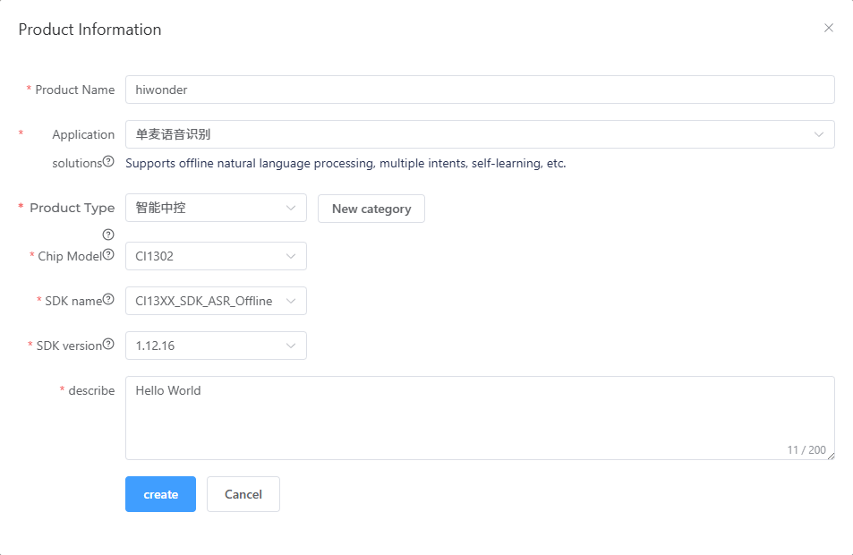
The product name and description can be customized. For the application scheme, select Single microphone voice recognition.
on the left. Then create a new product as shown in the below image.
The product name and description can be customized. For the application scheme, select Single microphone voice recognition.
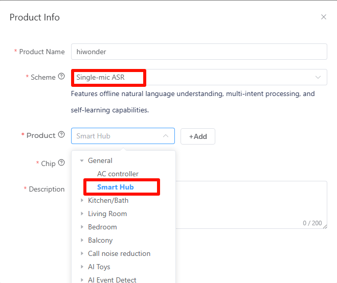
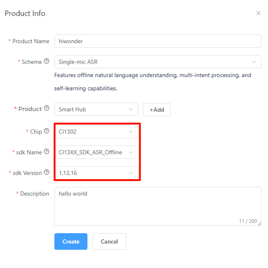
In the pop-up parameter options, select General -> Smart Central Control for the product type, and choose CI1302 for the chip model. Next, choose CI13XX_SDK_ASR_Offline for the SDK name.
Select the SDK version as 1.12.16. Once all options are configured, click Create.
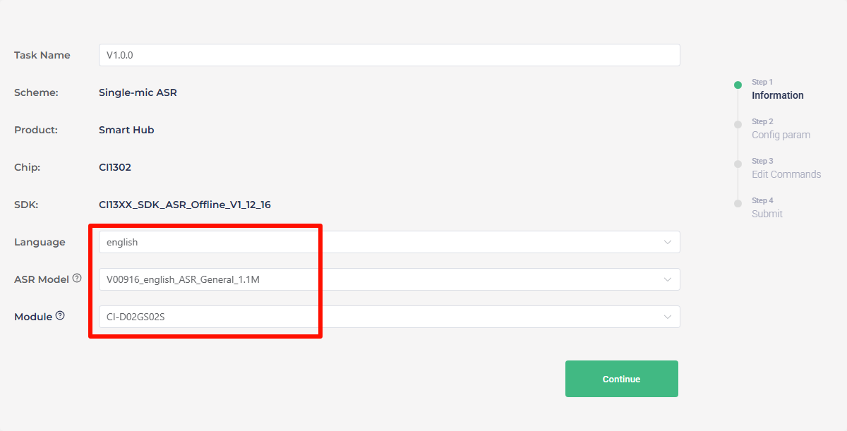
Then fill in the basic information for the project. Select English for the language type. Fill in the other information as shown in the image, and then click Continue to proceed.
To configure for English recognition, follow the same steps with the corresponding settings.
Once entering the firmware configuration interface, focus on the steps for modifying key parameters. First, in the Algorithm Parameters section, enable the Echo Cancellation function.

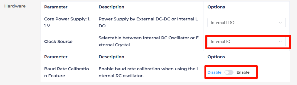
In the hardware parameters section, set the Crystal Oscillator Source to Internal RC and disable Baud Rate Calibration.
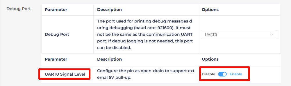
In the UART Print Settings, configure UART0 to Open-Drain Mode, supporting external 5V pull-up.
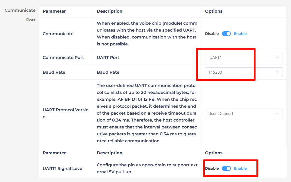
Modify the communication serial port configuration, set the Baud Rate to 115200 and configure UART1 to Open-Drain Mode, also supporting external 5V pull-up. After adjusting these settings, click Continue to move forward.
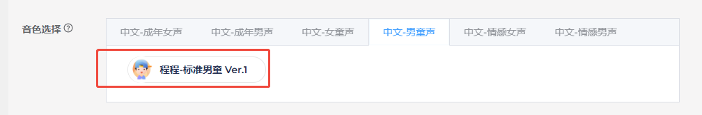
The next step involves configuring the entries. First, choose a voice output. Here selecting Dane – English Male Voice as an example.
Note
In the WonderLLM offline speech function, the selected voice tone here is the tone used by the module while interacting.
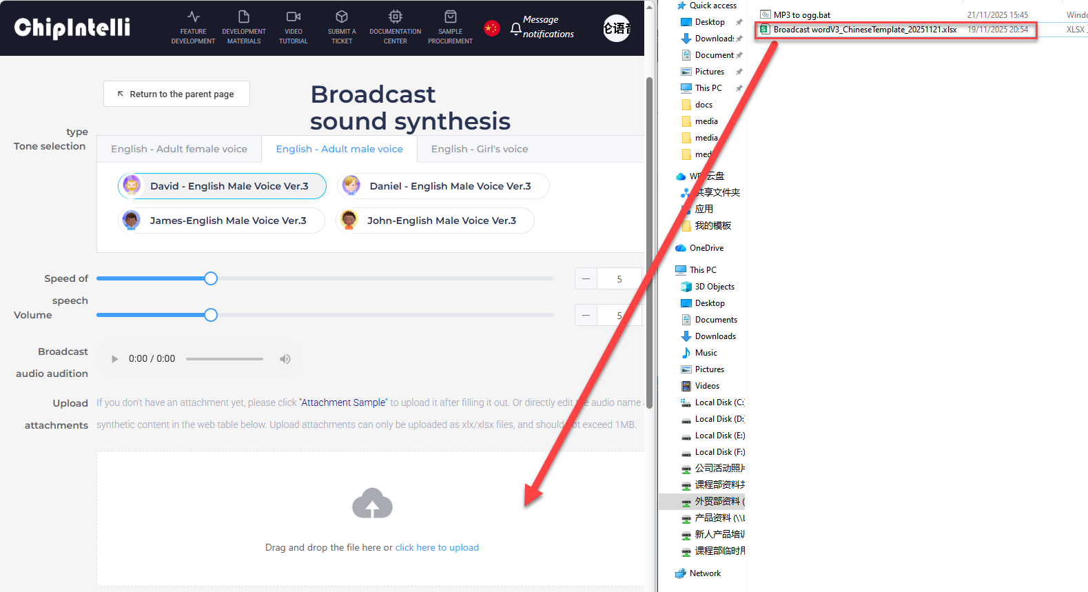
Upload the modified backup Command Word Broadcast Word Protocol List file by dragging it directly into the webpage for uploading.
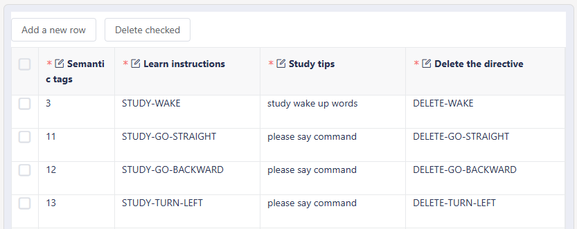
After uploading the file, the term data will be displayed in the table below. Scroll down the page, open Self-learning Function, and select Designated Learning from the pop-up Self-learning Method.

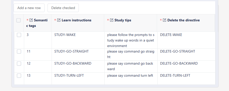
After selecting Self-learning Method, a list will automatically pop up on the page. The entries on the list are the entries for which the Modify Wake Word and Modify Command Word functions will be available in the generated CI1302 firmware. This list by default supports several entries from the uploaded Command Word Broadcast Word Protocol List file.
Note
In the above image, the term with semantic label 3 corresponds to the wake word, and the semantic entries 11-13 correspond to the command words “GO-STRAIGHT”, “GO-BACKWARD”, and “TURN-LEFT”.
The list supports manual modification. As shown in the figure below, simplify and modify the Learning Hint for several entries.
Note
Learning Instruction and Deletion Instruction can also be modified, but in firmware creation, all content in these two columns must be written in uppercase letters and use hyphens (-) to separate multiple words.
It is not recommended to modify semantic labels. If a term corresponding to a semantic label does not require enabling the self-learning function, it is advised to delete the entire row. If additional self-learning functionality is needed for other command words, refer to the following operations.
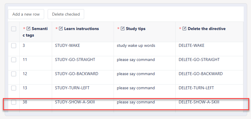
The list also supports add and delete operations. As shown in the figure below, add support for the Modify Command Word function for the command word term SHOW-A-SKIII with semantic label 38. First, click Add a new row at the top left of the list, then fill in the information for this term in the blank row at the bottom of the list.
Note
In this list, different entries cannot share the same “Learning Instruction” or “Deletion Instruction”. Only “Learning Hint” can be the same.
“Learning Instruction” and “Deletion Instruction” can be filled in freely. It is recommended to fill the “Learning Instruction” for term xx as “STUDY-XX” and the “Deletion Instruction” as “DELETE-XX”.

After completing the above operations, click Submit now at the bottom of the page to start generating the firmware.

After submission, wait for a few minutes to complete the firmware creation. Once finished, click Download file to obtain the generated firmware.
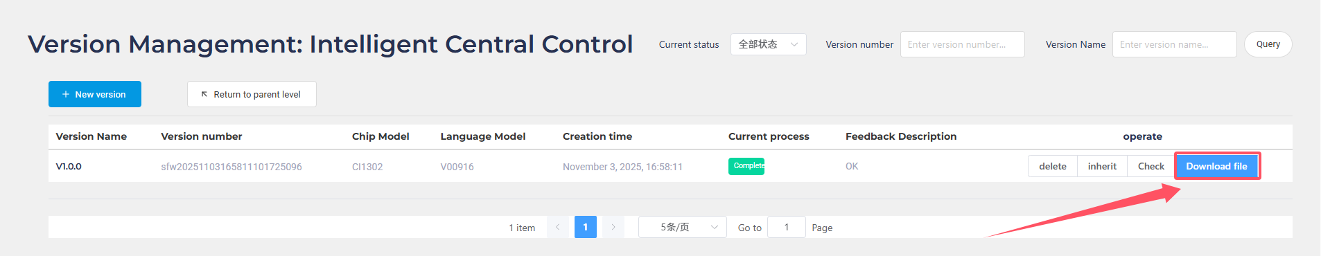
Once the firmware download is complete, a compressed file will be obtained. After extracting it, a
.binfile will be stored inside. Refer to 4.2.1 CI1302 Firmware Flashing for instructions on flashing it to the CI1302 chip.
4.8.2 ESP32S3 Firmware Creation
First, open the link to the “Chipintelli Voice AI Platform” to access the firmware creation official website.
Click the Platform Functions. Then click on Deep development of product firmware and SDK under the Product Development section.
The system will prompt for a login. If registration is not completed, complete the platform account registration first. In this example, registration has already been completed in advance. After logging in successfully, click FEATURE DEVELOPMENT, and then click Broadcast Audio Synthesis.
After the page redirects, click the image on the left
. In the project details page, Project Name can be filled in freely, Voice Type should be selected based on actual needs, Tone Type can be selected freely, and other options should remain default.
Note
Since the CI1302 chip only supports Chinese/English voice recognition, it is recommended to select only Chinese or English in “Broadcast Audio Synthesis” to maintain consistency between the voice recognition and broadcasting language.
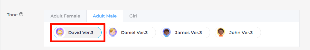
It is recommended to choose the same tone type as the one used when creating the CI1302 firmware. The factory firmware uses “David - English Male Voice Ver. 3” tone.
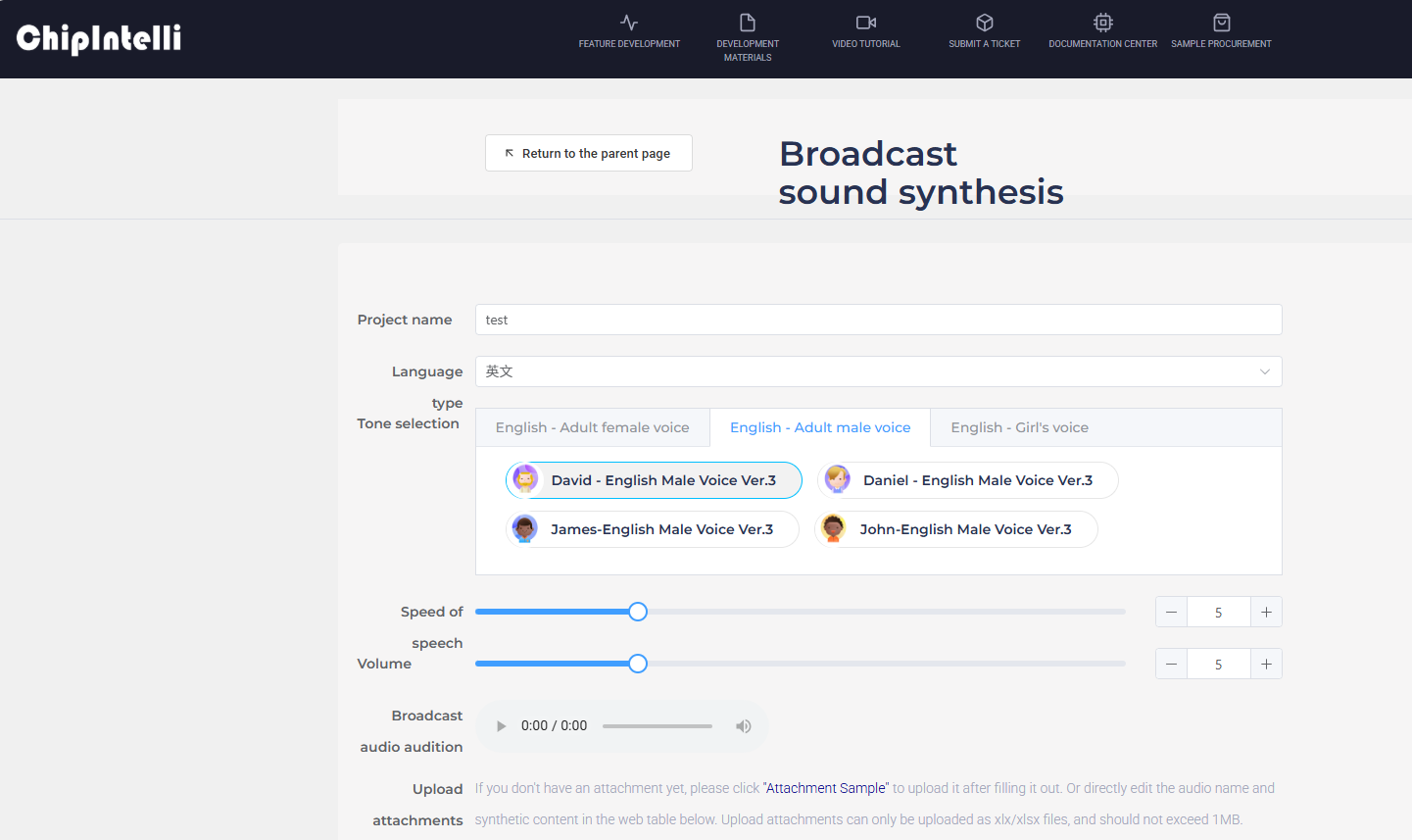
Next, upload the modified backup Broadcast Word V3_English Template file by dragging the file directly into the webpage for upload.
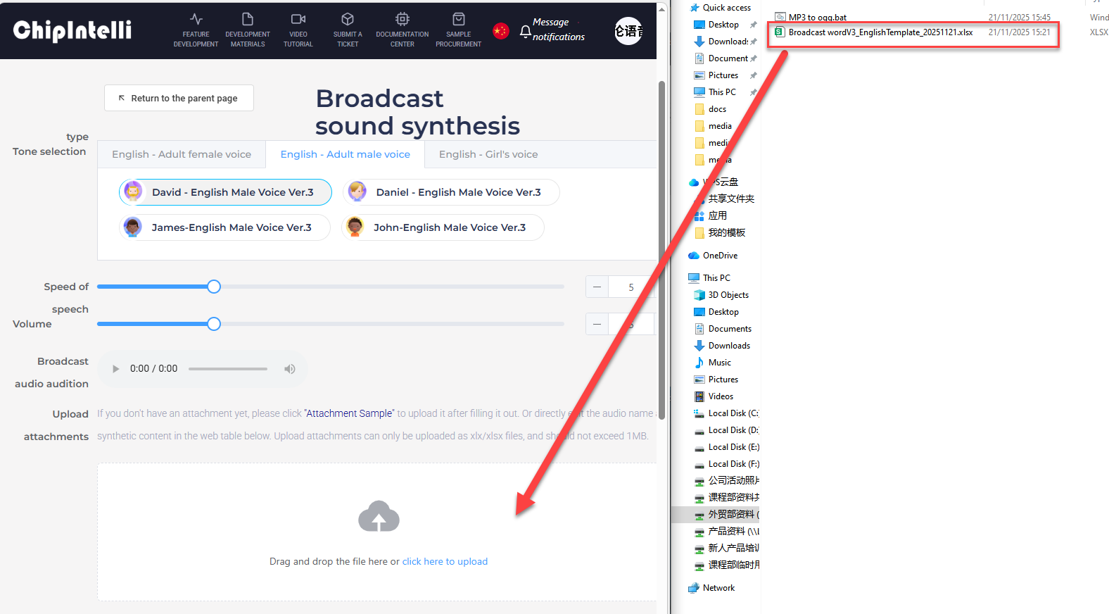
After completing the above operations, click Submit now at the bottom of the page to start generating term auto.
After submitting, wait for a few minutes to complete the audio generation. Once finished, click Download the file to obtain the generated audio.

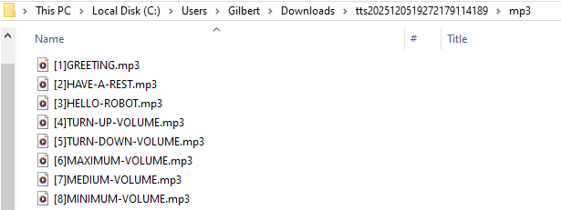
Once the firmware download is complete, extract the compressed file, then navigate to and open the internal mp3 folder.
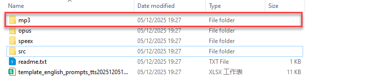
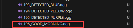
Inside the folder, find the audio files corresponding to the entries in the Broadcast Word V3_English Template file we submitted. The audio files are in mp3 format and are named according to the term Audio Name.
In the path “Appendix/11 Audio Conversion Tool”, locate the compressed file for the audio conversion tool installation package. Set up the working environment for the tool as detailed in 4.8.3 Audio Conversion Tool Environment Setup (Optional).
Note
The environment setup is required only for the first use. For subsequent uses, skip this step.
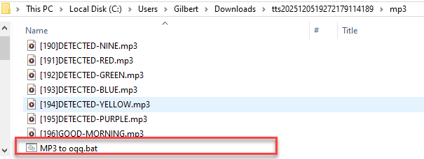
In the path “Appendix/11 Audio Conversion Tool”, locate the audio conversion script file MP3 to ogg.bat and copy it to the previously opened mp3 folder.
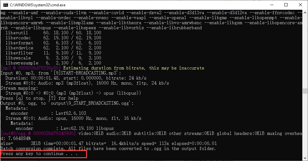
Double-click to run the script file. A pop-up window will appear during script execution, as shown in the image below. When the pop-up stops outputting and shows press any key to continue…, it indicates that the entire conversion process is complete, and the pop-up can be closed at this point.
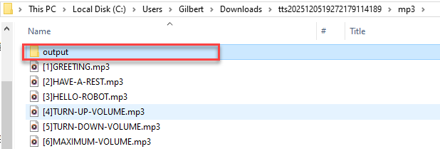
Once the script execution is complete, a subfolder output will be automatically created inside the mp3 folder. Click to enter it.
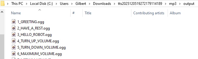
The output subfolder contains the same audio files as in the mp3 folder, but their format has been converted to the audio file format ogg, which is supported by the ESP32S3 controller. Open this folder for future use.
In the path “Appendix/12 WonderLLM Offline Voice Function Source Code”, locate the corresponding version. Copy and paste the source project to another location for backup.
Note
This step uses the “Desktop” folder as an example.
Do not make direct changes to the original file to avoid irreversible errors.

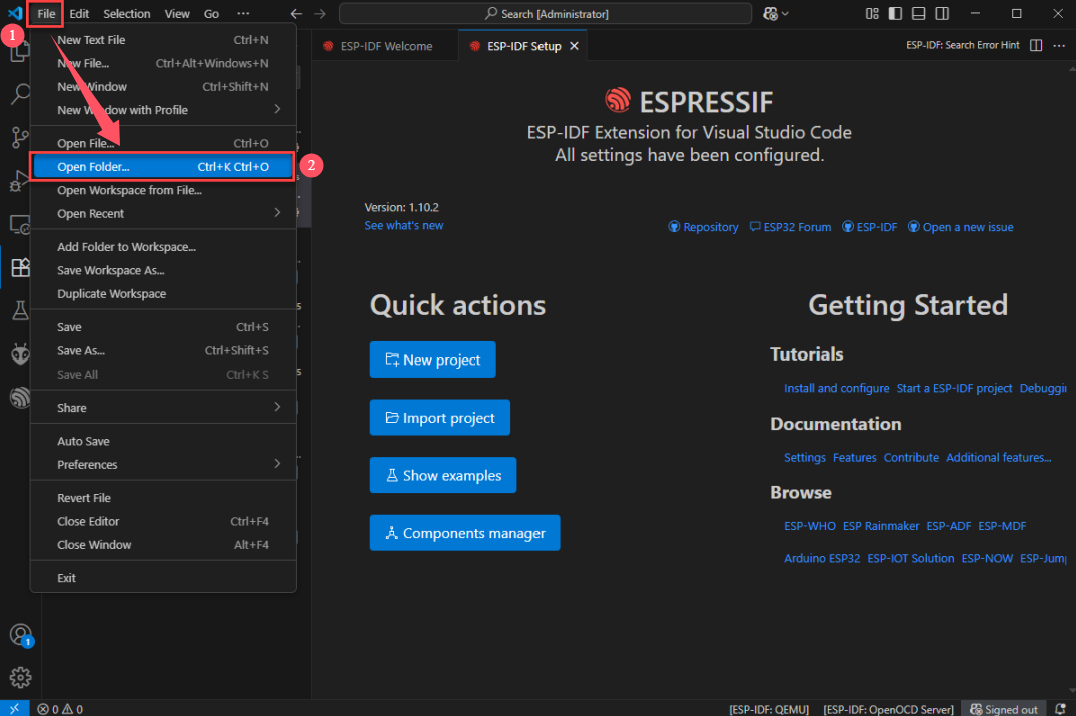
Using the completed ESP-IDF development environment in VSCode, click File - Open Folder.
Note
The specific environment setup process is explained in “2.6.1 XiaoZhi Open Source Program Description/Development Environment Deployment”, so it will not be elaborated here.
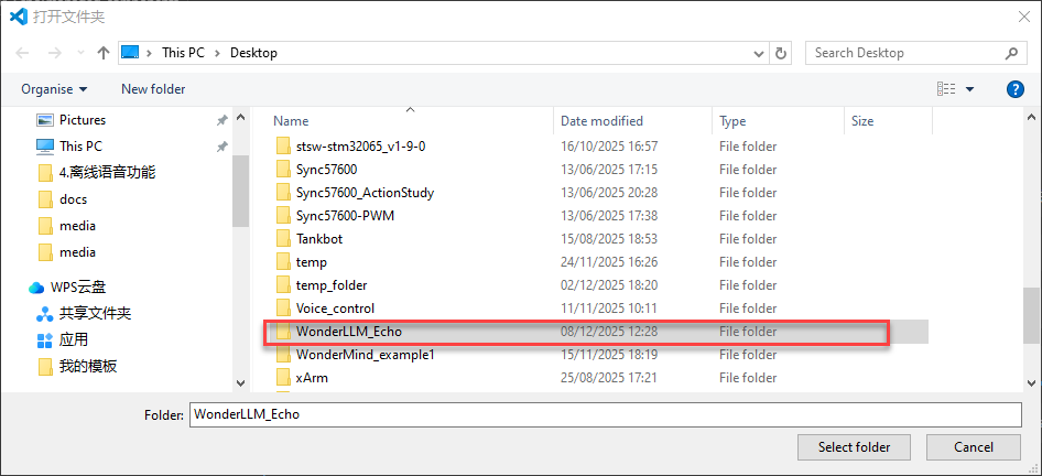
Select the copied backup source project folder WonderLLM_Echo and open it.
Note
If VSCode shows a pop-up asking whether to trust the folder’s author, choose to trust it. Otherwise, the ESP-IDF plugin will have limited functionality.
In the project main/assets path, place all the term audio files needed for the firmware.
Note
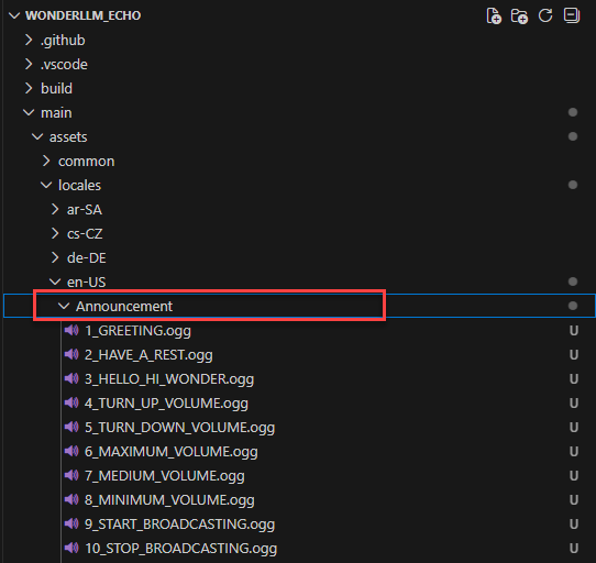
The audio files used in the factory firmware are stored in the “en-US” folder, as shown in the image below.
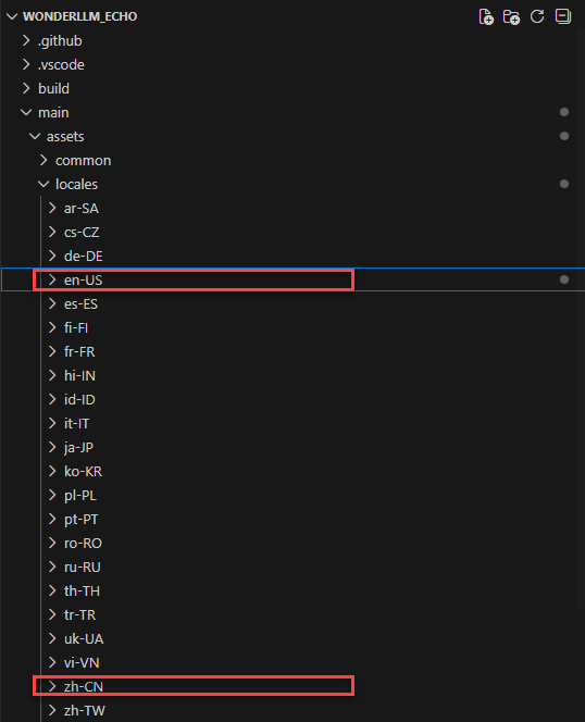
Expand the en-US folder. The .ogg audio files stored in this folder are the system audio files used during the module’s operation and do not require any modifications. The Announcement subfolder contains all the term audio files for functional entries, command word types, and broadcast word types. This folder is used to store user files.
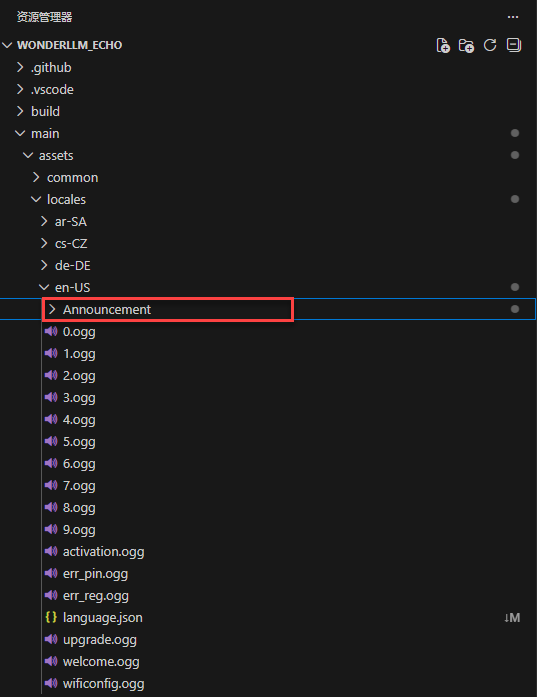
Expand the Announcement folder. It can be seen that all the term audio files matching the factory firmware have already been pre-stored in this path “Appendix/ 05 Command Word Broadcast Word Protocol List/ 01 Command Word Protocol List/Command Word Broadcast Protocol List” and “Appendix/05 Command Word Broadcast Word Protocol List/02 Broadcast Word Protocol List//Broadcast Word V3_English_Template” files).
Open the mp3/output folder mentioned in step 14. If any type of term has been added/modified in the original factory firmware (the operations in 4.5 Modify Functional Entries, 4.6 Add New Command Entries, and 4.7 Add Broadcast Words, all the .ogg audio files for the modified entries need to be pasted into the main/assets/locales/en-US/Announcement path of the backup source project, in sequence.
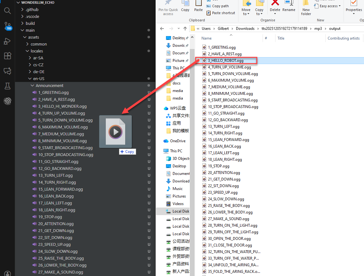
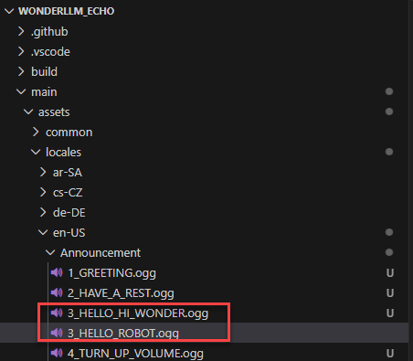
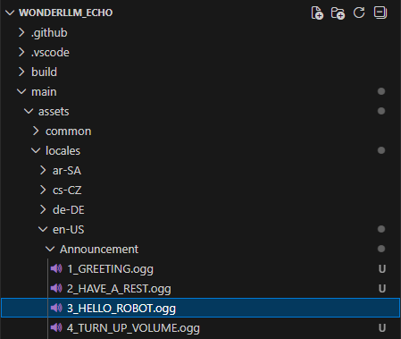
If new entries have been added, simply paste the corresponding synthesized .ogg audio files. If existing entries have been modified, after pasting the .ogg audio file for the modified term, there will be two .ogg audio files with the same semantic label (number) + underscore as the prefix in the main/assets/locales/en-US/Announcement path of the backup source project. These two files correspond to the audio files used before and after the modification of the term. Delete the audio file used before the modification.
Note
In this path, each .ogg file must be named with a unique “semantic label (number) + underscore” as the prefix, otherwise conflicts will occur during later use.
After that, begin modifying the source code files and synchronize the updates for the modified/added entries with the corresponding audio file mappings. There are a total of 2 places to update.
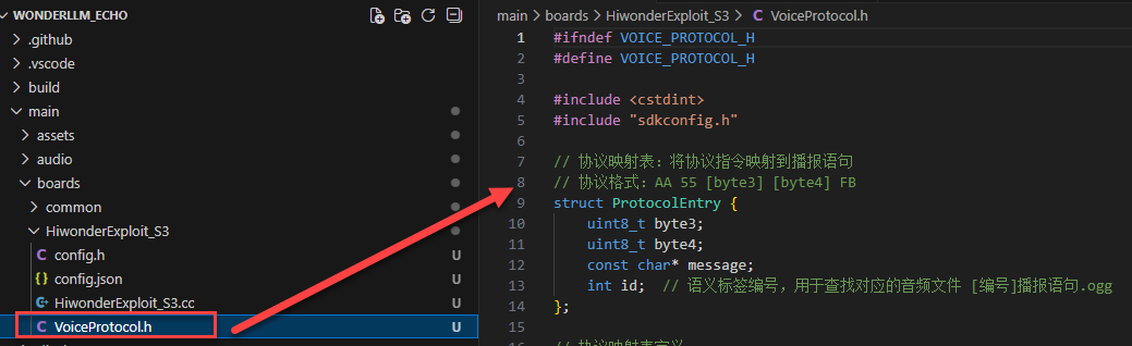
The first place: In the backup source project, navigate to main/boards/HiwonderExploit_S3 and open the VoiceProtocol.h file. This file links the term broadcast to the corresponding broadcast statement, which is also displayed on the screen.
Locate and open the code under the “/#elif CONFIG_LANGUAGE_EN_US” branch.
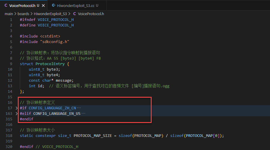
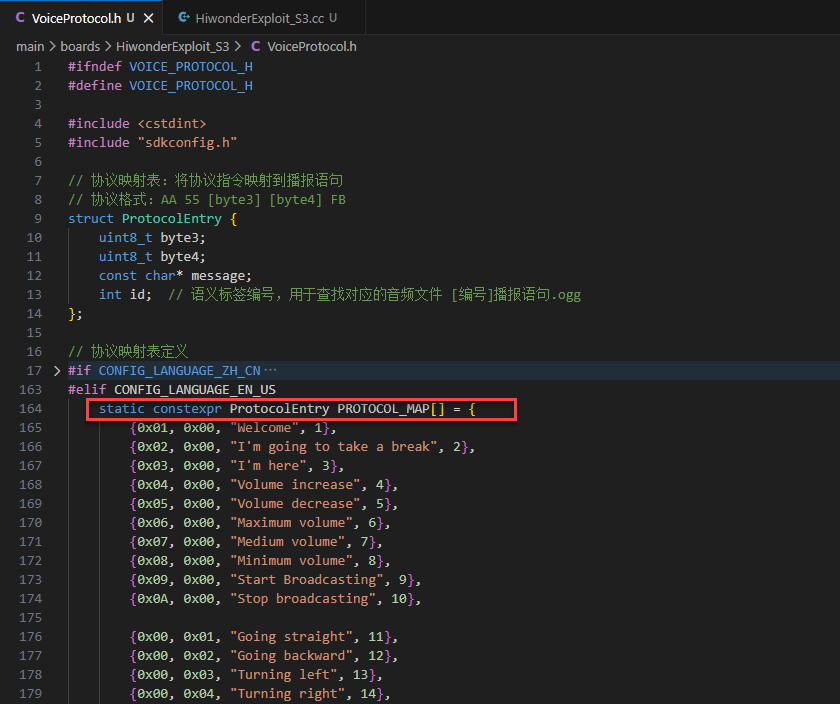
Depending on the language version of the firmware, open the corresponding branch code and find the PROTOCOL_MAP array.
Note
The data arrangement format for each element in the array is: {Term send/receive protocol 3rd byte, Term send/receive protocol 4th byte, Term broadcast statement, Term semantic label}.
For the term send/receive protocol, broadcast statement, and semantic label, refer to the “Command Word Broadcast Word Protocol List” file.
If any existing entries have been modified, the latest broadcast statement for the term must be updated in the corresponding array element. For example, if the wake word has been modified, make the corresponding changes in the program file as shown in the image below.
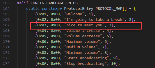
If new entries are added, follow the data arrangement format: “{Term send/receive protocol 3rd byte, Term send/receive protocol 4th byte, Term broadcast statement, Term semantic label}”, and add a new line in the code with the corresponding information.
Note
The elements of the “PROTOCOL_MAP” array are arranged in ascending order of semantic labels, from top to bottom. For better program readability and maintainability, it is recommended to insert new entries in the corresponding position according to their numerical order.
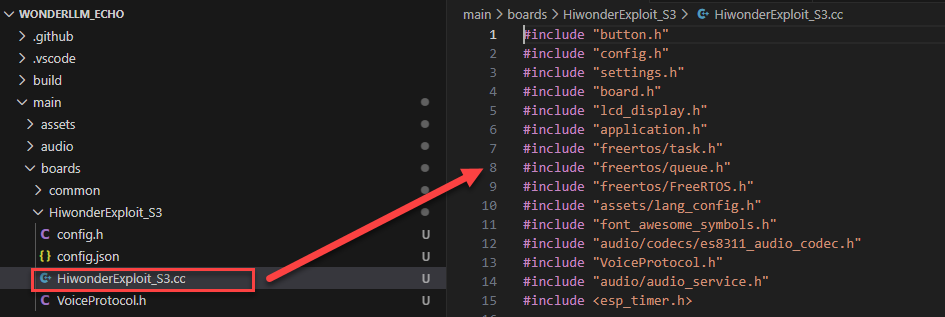
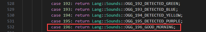
The second place: In the backup source project, navigate to main/boards/HiwonderExploit_S3 and open the HiwonderExploit_S3.cc file. This file links the term broadcast to the corresponding audio file that is called when the broadcast statement is played.
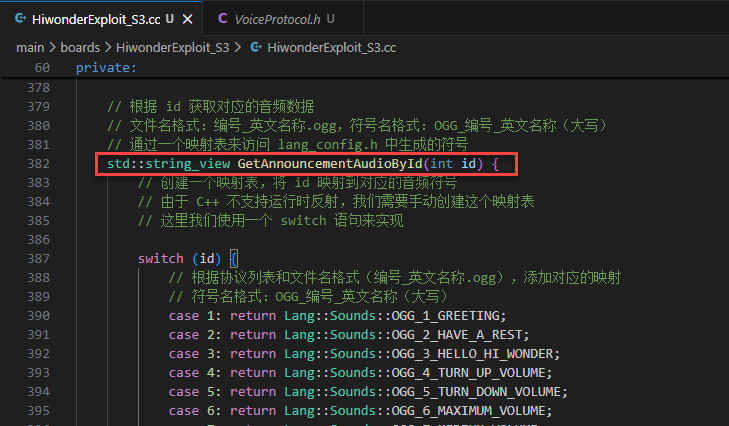
Locate the
GetAnnouncementAudioByIdfunction. In the function’s switch case, the branch values correspond to the semantic labels of the entries.
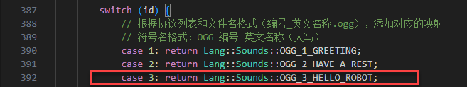
If any existing entries have been modified, the latest broadcast statement audio file name must be updated in the corresponding array element. For example, if the wake word has been modified, make the corresponding changes in the program file as shown in the image below.
Note
The imported audio file names need to be compiled with ESP-IDF. The files generated after compilation are the ones that will be called by the final program. The compiled files are automatically named as “OGG_Imported Audio File Name”.
If new entries are added, follow the format: “OGG_Imported Audio File Name”, add a new line in the code and fill in the corresponding information.
Note
The switch cases are arranged in ascending order of semantic labels, from top to bottom. For better program readability and maintainability, it is recommend to insert new entries in the corresponding position according to their numerical order.
Connect WonderLLM to the computer. Click the icon shown in the lower extension bar and select the device’s serial port.
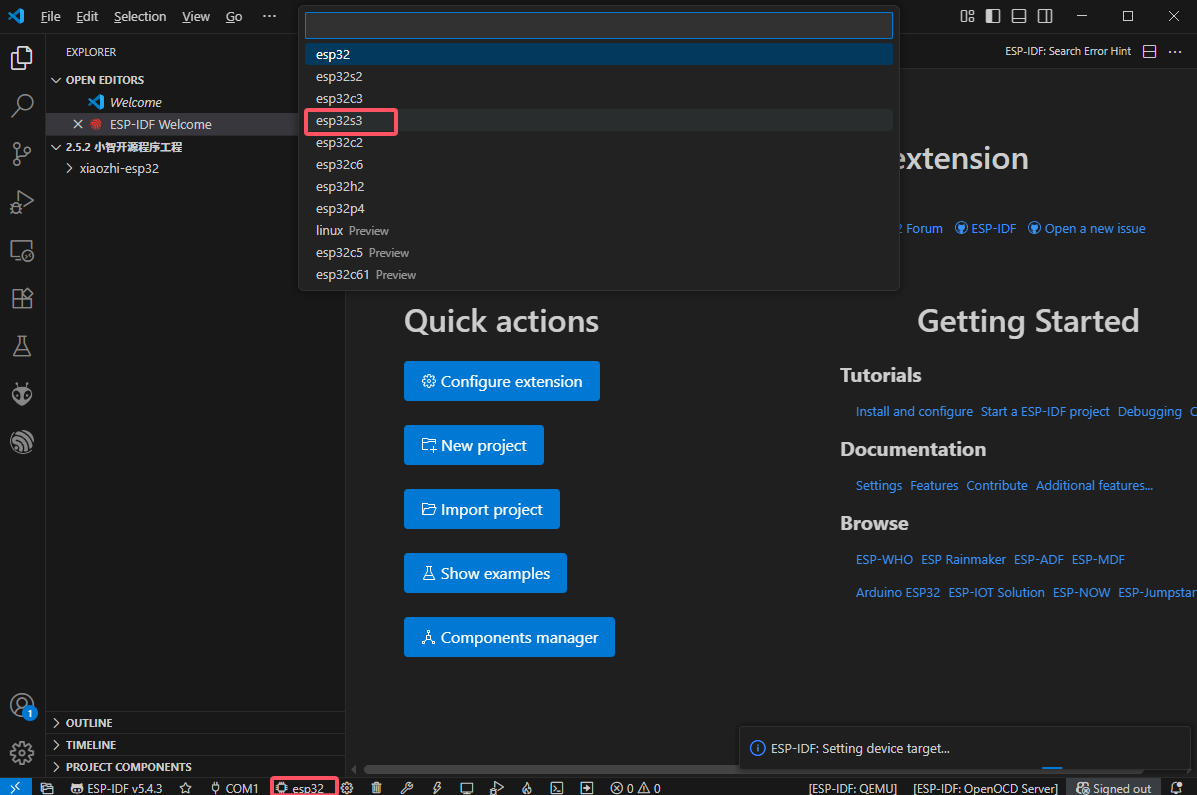
Click the icon shown in the lower extension bar and select the chip model as ESP32S3.
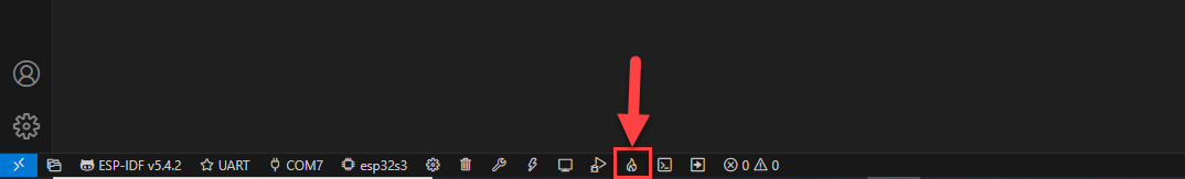
Click the icon shown in the lower extension bar to automatically invoke ESP-IDF to build, flash, and monitor the current project sequentially. The initial project build may take some time. Please wait a moment.
When the terminal outputs the following prompt, it indicates that the project build is successful.
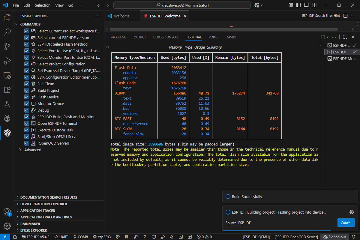
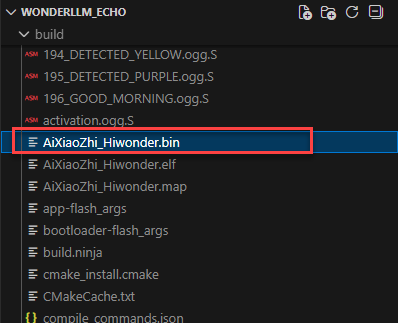
Note
After ESP-IDF compilation is complete, a build folder will be generated in the root directory of the project to store the compiled output files, including the AiXiaoZhi_Hiwonder.bin file. This firmware can later be flashed to the ESP32S3 controller following the “4.2.2 ESP32S3 Firmware Flashing” method.
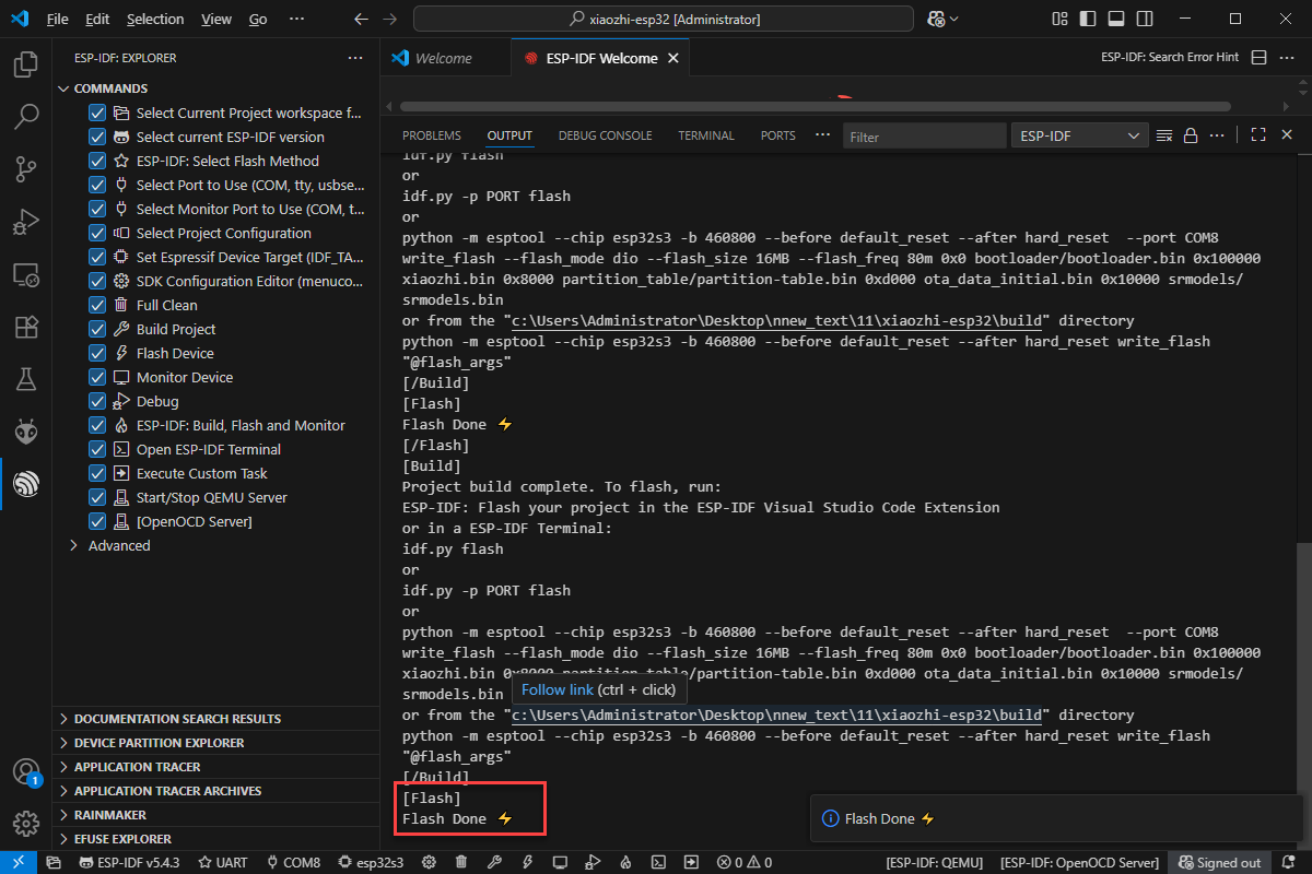
When the terminal outputs the following prompt, it indicates that the project has been successfully flashed.
4.8.3 Audio Conversion Tool Environment Setup (Optional)
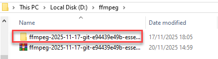
In the path “Appendix/11 Audio Conversion Tool”, locate the audio conversion tool installation package and copy it to any directory.
Note
It is recommended to create a new folder with the same name in the root directory of the disk and place the installation package inside. In this document, the newly created path “D:/ffmpeg” is used as an example.
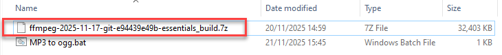
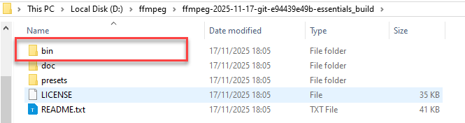
Extract the compressed file directly in this path.
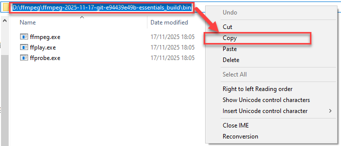
Enter the extracted folder, then navigate to the bin folder inside and locate the audio conversion tool.
In the audio conversion tool’s ffmpeg.exe path, copy the path for future use.
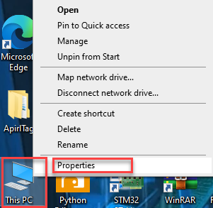
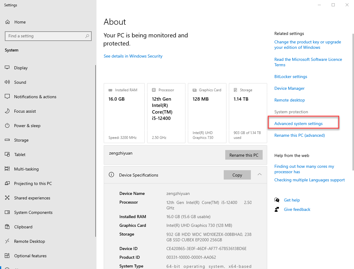
Return to the DeskTop screen, left-click to select the This PC icon, right-click, and choose Properties from the context menu.
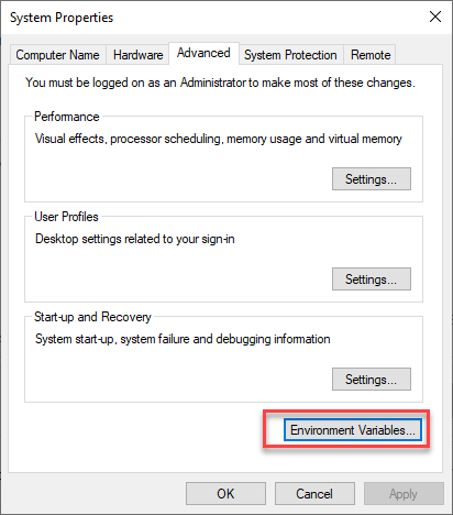
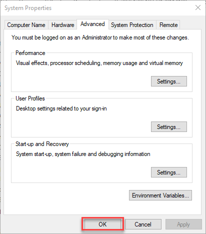
In the opened window, select Advanced system settings.
In the opened window, select Environment Variables.
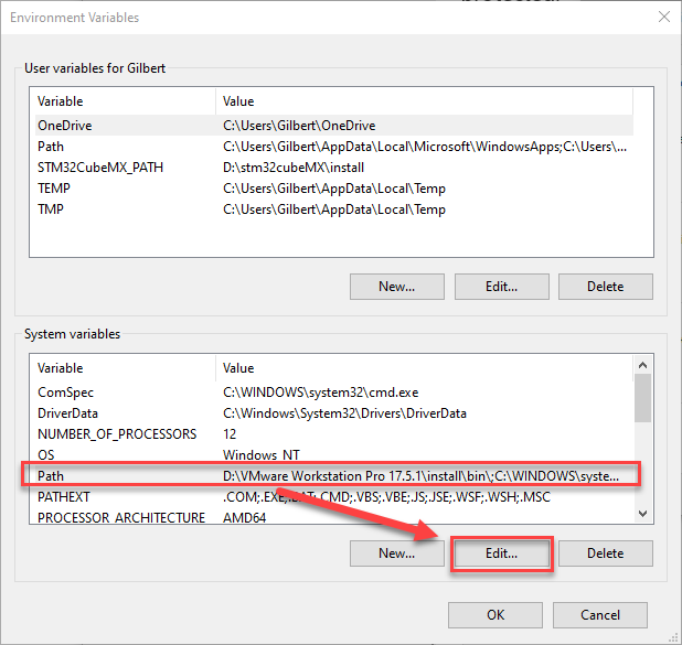
In the opened window, under the System variables section, left-click to select the Path variable, then click the Edit… icon.
In the opened window, click New to add a new value for the variable.
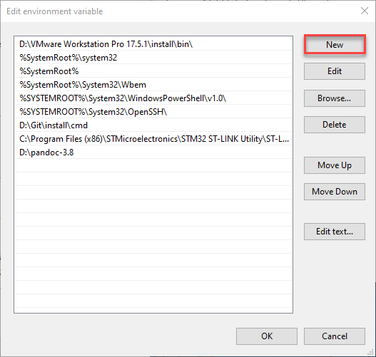
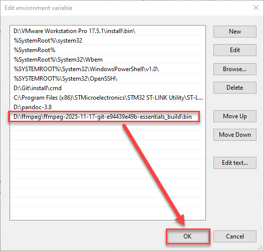
Paste the previously copied audio conversion tool ffmpeg.exe path here, then click OK to save the changes. The Edit environment variable window will close automatically.
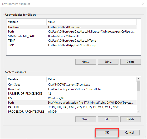
In the Environment variables window, click OK to save the changes. This window will close automatically.
In the System Properties window, click OK to save the changes. This window will close automatically.
After completing the above steps, the environment setup for the audio conversion tool is finished.
4.9 Device Controller-Device Communication Principles & Register Description
This section introduces the detailed information about the controller–device relationship when the WonderLLM module communicates with different controller such as Arduino, STM32. It explains how WonderLLM acts as a device in communication with other controllers and how these controllers access and control the WonderLLM data.
In this chapter, the WonderLLM module is always used as a device, transmitting information with other devices via the I2C protocol.
4.9.1 Controller–Device Relationship
In a controller–device communication system, the WonderLLM module acts as the subordinate device, while other microcontrollers or devices serve as the master.
WonderLLM module as the subordinate device
Receiving and Parsing Signals from the Controller: It waits for I2C signal interrupts. When data is received via I2C, the module calls the corresponding function based on the register address information.
Data Processing and Feedback: When the WonderLLM receives a register read command, it calls the corresponding send function to transmit the detected data to the master device.
Other Devices as the Controller
Command Sending: The controlling device needs to send data read commands to the WonderLLM Module.
Control coordination: The controlling device manages the coordination of the entire system, ensuring that communication and operations between the controlling device, the WonderLLM module, and any other devices connected to the controlling device do not conflict, maintaining proper system functionality.
Data reception: When the controlling device reads data, after sending the read command, it needs to receive status information from the WonderLLM, parse the data packet, and extract the useful information.
4.9.2 I2C Device Address and Function Registers
The I2C device address of the WonderLLM module is set to 0x34 by default.
| Register | Description |
| 0x64 | This register stores the recognized result. The master needs to read 1 byte of data, which corresponds to the ID number of the recognition result. (If no result is recognized, the value will be 0x00.) |
| 0x6E | This register sets the broadcast speech. The master needs to send 2 bytes of data. (The first byte is 0x00 or 0xFF: 0x00 for command word broadcast type, 0xFF for general broadcast type. The second byte is the ID number.) |
4.9.3 I2C Device Address Modification and Address Registers
In scenarios where multiple modules or sensors are used, the I2C address of the WonderLLM module may conflict with other modules (such as Hiwonder’s WonderLLM module with the 4CH Motor Driver Module, or WonderEcho WonderLLM module). The WonderLLM module provides an I2C address modification function, with the specific details as follows:
| Register | Description |
| 0x03 | This register sets the module's I2C address. The master needs to send 1 byte of data. Possible values: 0x33/0x34, other values are invalid. The default value of the register is 0x34. |
Note
Once the valid data is written to this register, the module will begin switching its internal I2C device address.
The internal I2C device address switch requires some time. If a command is sent to the WonderLLM module immediately after switching to the new I2C address, the module will not respond correctly. To ensure proper communication, please wait at least 100ms before attempting to communicate with the module using the new address.
4.9.4 Notice
The power supply of the controlling device and the WonderLLM module can be different. However, they must share a common ground when connected to ensure stable communication levels.
4.10 Command Word Broadcast Word ID Analysis
In the path “Appendix/05 Command Word Broadcast Word Protocol List/01 Command Word Protocol List”, locate the Command Word Broadcast Word Protocol List document corresponding to the factory firmware. This document is the communication protocol between the CI1302 chip and the ESP32S3 chip.
The protocol starts with 0xAA and 0x55, and ends with 0xFB. The two bytes in the middle represent the function type and ID number.
4.10.1 Functional Entries
The first part of the protocol document consists of the functional entries for speech recognition. These entries are used to configure the WonderLLM module and generally remain unchanged.
4.10. 2 Command Word Type Entries
An example of a recognized command word is shown below, where the two bytes in the middle of the command word are 0x00 and the ID number. For example:
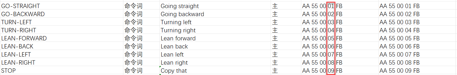
For example, when the WonderLLM module recognizes the “go straight” command word, it will respond with “going straight”. The controller can read 0x01 as a byte from the recognition result register (0x64), which is the same as the 4th byte in the sending protocol for “go straight”.
4.10. 3 Broadcast Word Type Entries
Broadcast phrase entries are not played automatically. Playback is triggered only when the controller configures them via I2C. Broadcast phrases associated with command entries can also be played.
The controller writes 2 bytes to the broadcast register at address 0x6E via I²C. The first byte specifies the type, and the second byte specifies the ID. The speech module then plays the corresponding phrase. Two common types exist: 0x00 for command word phrases, corresponding to the broadcast phrases in “2. Command Word Type Entries”, and 0xFF for general phrases.
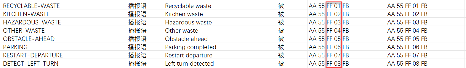
Example 1: To play the broadcast phrase entry recycle waste, the controller writes 0xFF 0x02 to the broadcast register (0x6E) via I2C. The WonderLLM module then plays recycle waste.
Example 2: To play the command phrase entry turn left, the controller writes 0x00 0x03 to the broadcast register (0x6E) via I2C. The WonderLLM module then plays turn left.
(Extended) Example 3: The broadcast statement of functional entries also supports broadcasting. For example, when the wake word greeting needs to be played, the controller needs to write 0x01 0x00 to the broadcast register (0x6E) via I2C. The WonderLLM module will then broadcast welcome.
4.11 Communication with Arduino Controller
4.11.1 Arduino Speech Recognition Example
Preparation
Wiring Instruction
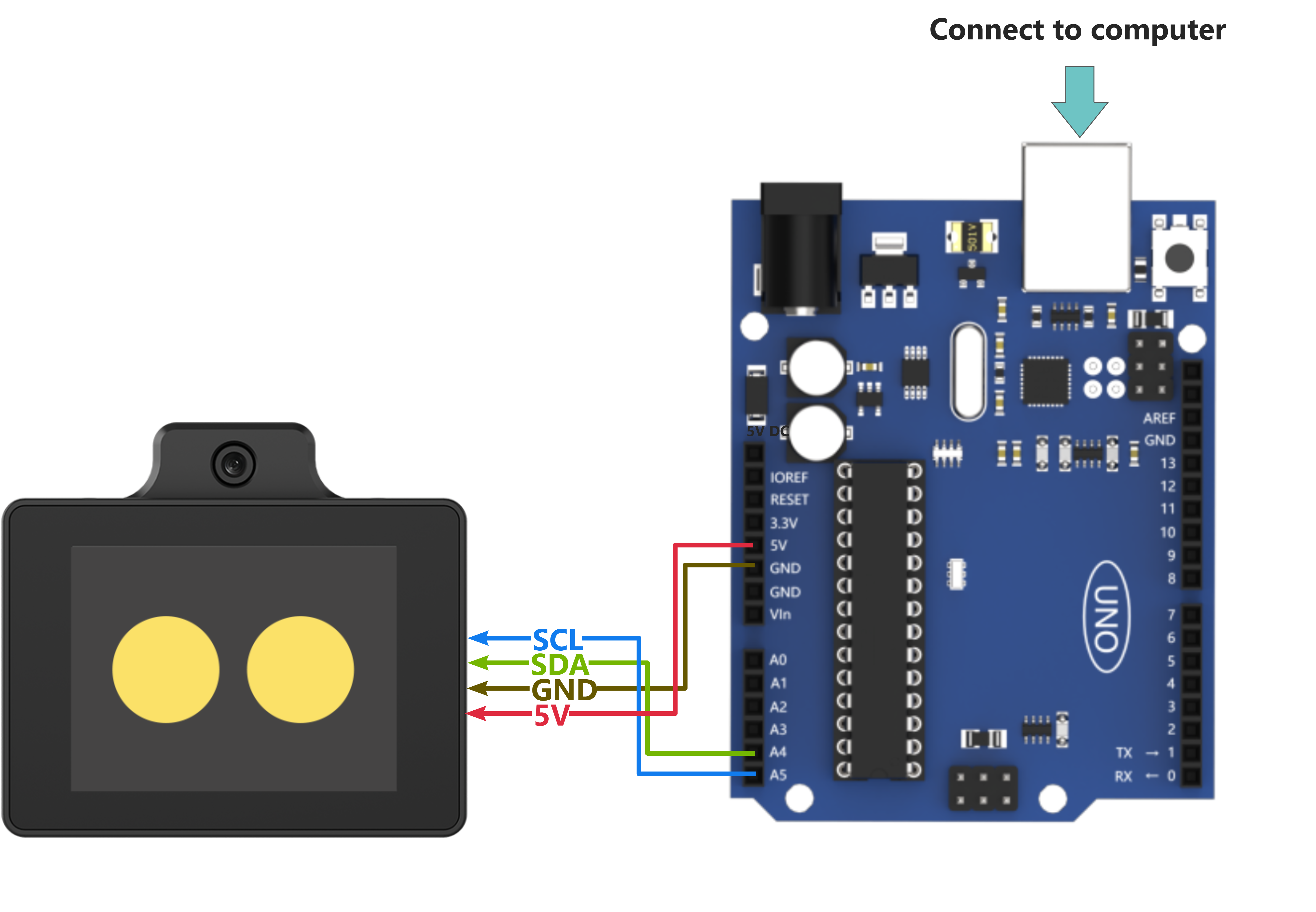
(1) When wiring, connect the WonderLLM’s 5V, GND, SCL, and SDA pins to the Arduino UNO development board as shown in the diagram below:
(2) The Arduino UNO development board can be used with any of our Arduino expansion boards, and the wiring with WonderLLM is shown below (using Board A as an example):
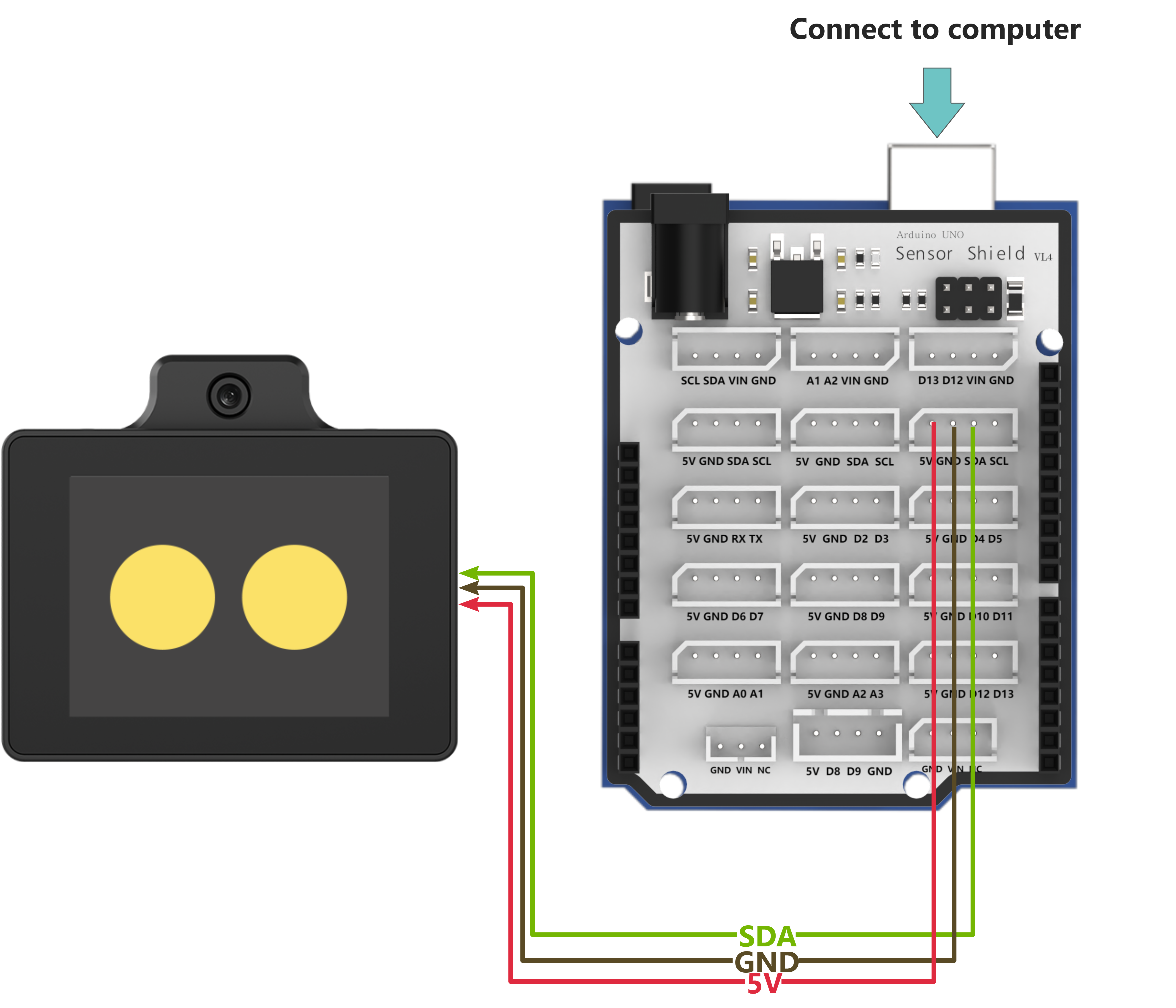
Note
Before powering on, ensure that no metal objects are touching the controller. Otherwise, the exposed pins at the bottom of the board may cause a short circuit and damage the controller.
Arduino Program Download
(1) Connect the Arduino controller to the computer via USB cable.
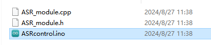
(2) Open the Appendix/06 Arduino Program Files/01 Arduino Speech Recognition Example/ASRcontrol/ASRcontrol.ino program file in the same path as this document.
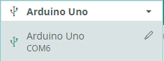
(3) Select Arduino UNO as the development board and choose the correct port number.
(4) Click  to download the program to the Arduino and wait for the download to complete.


Test Case
This section uses the Arduino controller to obtain the recognition results from the WonderLLM module and print them through the serial port.
Project Outcome
Note
Before recognition, the module needs to hear “Hello Hiwonder” to wake up the module, after which it can perform recognition.
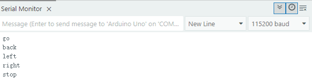
(1) When the WonderLLM module recognizes the go straight entry, it will respond with going straight, and the serial port will print go;
(2) When the WonderLLM module recognizes the backward entry, it will respond with going backward, and the serial port will print back;
(3) When the WonderLLM module recognizes the turn left entry, it will respond with turning left, and the serial port will print left;
(4) When the WonderLLM module recognizes the turn right entry, it will respond with turning right, and the serial port will print right;
(5) When the WonderLLM module recognizes the stop or halt entry, it will respond with received, and the serial port will print stop;
The printed data is as follows:
Program Brief Analysis
(1) The program imports the Wire and ASR_module libraries, which are used for communication with WonderLLM module.
#include <Wire.h>
#include "ASR_module.h"
(2) Create an object for WonderLLM module and a variable result to receive recognition results from the module. The serial port baud rate is set to 115200.
ASR_MOUDLE asr;

uint8_t result = 0;

void setup()
{
  Serial.begin(115200);
  Serial.println("Start");
}
(3) In the main function, use the asr.rec_recognition() function to retrieve the data returned by the WonderLLM module.
void loop()
{
  result = asr.rec_recognition();  // Returns the recognition result, which is the ID number of the recognized entry
(4) When the go straight entry is recognized, it will return 0x01; when backward is recognized, it will return 0x02. Similarly, recognizing any entry will return the corresponding entry ID number.
Note
For the detailed list of returned data, please refer to the “Command Word Broadcast Word Protocol List”.
  if(result != 0)
  {
    if(result == 0x01)
    {
      Serial.println("go");
    }else if(result == 0x02)
    {
      Serial.println("back");
4.11.2 Arduino Speech Broadcast Example
Preparation
Wiring Instruction
(1) When wiring, connect the WonderLLM’s 5V, GND, SCL, and SDA pins to the Arduino UNO development board as shown in the diagram below:
(2) The Arduino UNO development board can be used with any of our Arduino expansion boards, and the wiring with WonderLLM is shown below (using Board A as an example):
Note
Before powering on, ensure that no metal objects are touching the controller. Otherwise, the exposed pins at the bottom of the board may cause a short circuit and damage the controller.
Arduino Program Download
(1) Connect the Arduino controller to the computer via USB cable.
(2) Open the Appendix/06 Arduino Program Files/02 Arduino Speech Boradcast Example/ASRcontrol/ASRcontrol.ino program file in the same path as this document.

(3) Select Arduino UNO as the development board and choose the correct port number.
(4) Click to download the program to the Arduino and wait for the download to complete.
Test Case
This example uses the Arduino development board to make the WonderLLM module loop through speech playback.
Project Outcome
The Arduino development board controls the WonderLLM module to broadcast the following messages every 5 seconds in sequence: going straight, turning left, recyclable, and hazardous waste.
Program Brief Analysis
(1) The program imports the Wire and ASR_module libraries, which are used for communication with WonderLLM module.
#include <Wire.h>
#include "ASR_module.h"
(2) Create an object for WonderLLM module and a variable result to receive recognition results from the module. The serial port baud rate is set to 115200.
ASR_MOUDLE asr;

uint8_t result = 0;

void setup()
{
  Serial.begin(115200);
  Serial.println("Start");
}
(3) In the main function, use the asr.speak() function to send data to the WonderLLM module. This function has two parameters:
Parameter 1: The register address for the command word or broadcast word.
Parameter 2: The value corresponding to the broadcast speech.
void ASR_MOUDLE::speak(uint8_t cmd , uint8_t id)
{
    send[0] = cmd;
    send[1] = id;
    WireWriteDataArray(ASR_SPEAK_ADDR , send , 2);
}
(4) ASR_CMDMAND is a macro definition with a value of 0x00, indicating that the type of function to be written is a command word. First, write 0x01 to the register address ASR_CMDMAND, which corresponds to the broadcast statement going straight. The data 0x03 corresponds to turning left in the data list.
void loop()
{
  asr.speak(ASR_CMDMAND, 0x01); // Command word broadcast speech: "going straight"
  delay(5000);
  asr.speak(ASR_CMDMAND, 0x03); // Command word broadcast speech: "turning left"
  delay(5000);
(5) ASR_ANNOUNCER has a value of 0xFF, indicating that the function type to be written is a broadcast speech. Write 0x01 to the register address ANNOUNCER, which corresponds to the broadcast statement “recyclable”. The data 0x03 corresponds to “hazardous waste” in the data list.
  asr.speak(ASR_ANNOUNCER, 0x01); // Broadcast speech: "recyclable"
  delay(5000);
  asr.speak(ASR_ANNOUNCER, 0x03); // Broadcast speech: "hazardous waste"
  delay(5000);
}
Note
The detailed list of returned data, please refer to the “Command Word Broadcast Word Protocol List”.
4.11.3 Arduino Module Address Modification Example
Preparation
Wiring Instruction
(1) When wiring, connect the WonderLLM’s 5V, GND, SCL, and SDA pins to the Arduino UNO development board as shown in the diagram below:
(2) The Arduino UNO development board can be used with any of our Arduino expansion boards, and the wiring with WonderLLM is shown below (using Board A as an example):
Note
Before powering on, ensure that no metal objects are touching the controller. Otherwise, the exposed pins at the bottom of the board may cause a short circuit and damage the controller.
Arduino Program Download
(1) Connect the Arduino controller to the computer via USB cable.
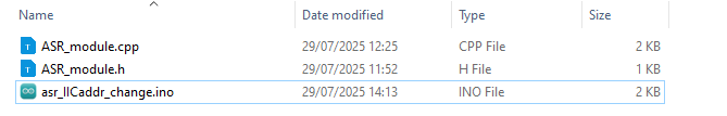
(2) Open the Appendix/06 Arduino Program Files/03 Arduino Address Modification Example/asr_IICaddr_change/asr_IICaddr_change.ino program file in the same path as this document.
(3) Select Arduino UNO as the development board and choose the correct port number.
(4) Click to download the program to the Arduino and wait for the download to complete.
Test Case
This example demonstrates how to use Arduino to repeatedly switch the I2C device address of the WonderLLM module and control the module to perform voice broadcasting via I2C communication using the new address.
Project Outcome
(1) The Arduino controls the WonderLLM module to switch its device address to 0x34, then uses this I2C address to sequentially play the voice broadcasting Going straight and Recyclable waste.
(2) Next, switch the WonderLLM module’s device address to 0x33, then uses this I2C address to sequentially perform the voice broadcasting Going straight and Recyclable waste.
(3) This process repeats in a loop.
Program Brief Analysis
(1) The program imports the Wire and ASR_module libraries, which are used for communication with WonderLLM module.
#include <Wire.h>
#include "ASR_module.h"
(2) Create an object for WonderLLM module and a variable result to receive recognition results from the module. The serial port baud rate is set to 115200.
ASR_MOUDLE asr;

void setup()
{
  Serial.begin(115200);
  Serial.println("Start");
}
(3) In the main function, the asr.ChangeAddr() function is called to write data to the WonderLLM module. This function takes the new I2C device address of the WonderLLM module as its parameter.
(4) The function first checks whether the new address new_addr is valid, whether it is one of the allowed values: 0x33 or 0x34. If the condition is not met, return 0 and exit. Otherwise, use the current module I2C address module_addr to communicate with the WonderLLM module, and pass the new address into the ASR_IIC_ADDR_CHANGE_ADDR register.
(5) After receiving the data, the module will begin switching its address and update the module_addr member, which records the current module I2C address, to the new address. It will then return 1 and exit.
int ASR_MOUDLE::ChangeAddr(uint8_t new_addr)
{
  if(new_addr == 0x33 || new_addr == 0x34)
  {
    WireWriteDataArray(this->module_addr, ASR_IIC_ADDR_CHANGE_ADDR, &new_addr,1);
    this->module_addr = new_addr;
    return 1;
  }else{
    return 0;
  }
}
(6) In the loop function, the program outputs a message to the serial port indicating that the module’s device address will be changed shortly. Then it calls the ChangeAddr function to modify the module’s address, and uses an if statement to check whether the write operation was successful.
void loop()
{
  delay(1000);

  Serial.println("now,asr module's I2C Address is 0x34!");
  if(asr.ChangeAddr(0x34)){
(7) If the operation is successful, print a message as a prompt, then delay for 100ms to wait for the internal I2C address switch to complete. After that, call the speak function to communicate with the module using the updated I2C address member module_addr, and control the module to broadcast: “going straight” and “recyclable”.
    Serial.println("Success!");
    delay(100);
    asr.speak(ASR_CMDMAND, 0x01); // Command word broadcast speech: "going straight"
    delay(2000);
    asr.speak(ASR_ANNOUNCER, 0x01); // Broadcast speech: "recyclable"
    delay(2000);
  }else{
    Serial.println("Fail!");
  }
Note
The detailed list of returned data, please refer to the “Command Word Broadcast Word Protocol List”.
4.12 Communication with ESP32 Controller
4.12.1 ESP32 Speech Recognition Example
Wiring Instructions
Note
MicroPython code can run on any microcontroller that supports MicroPython programming. This section uses Hiwonder ESP32 core board as an example.
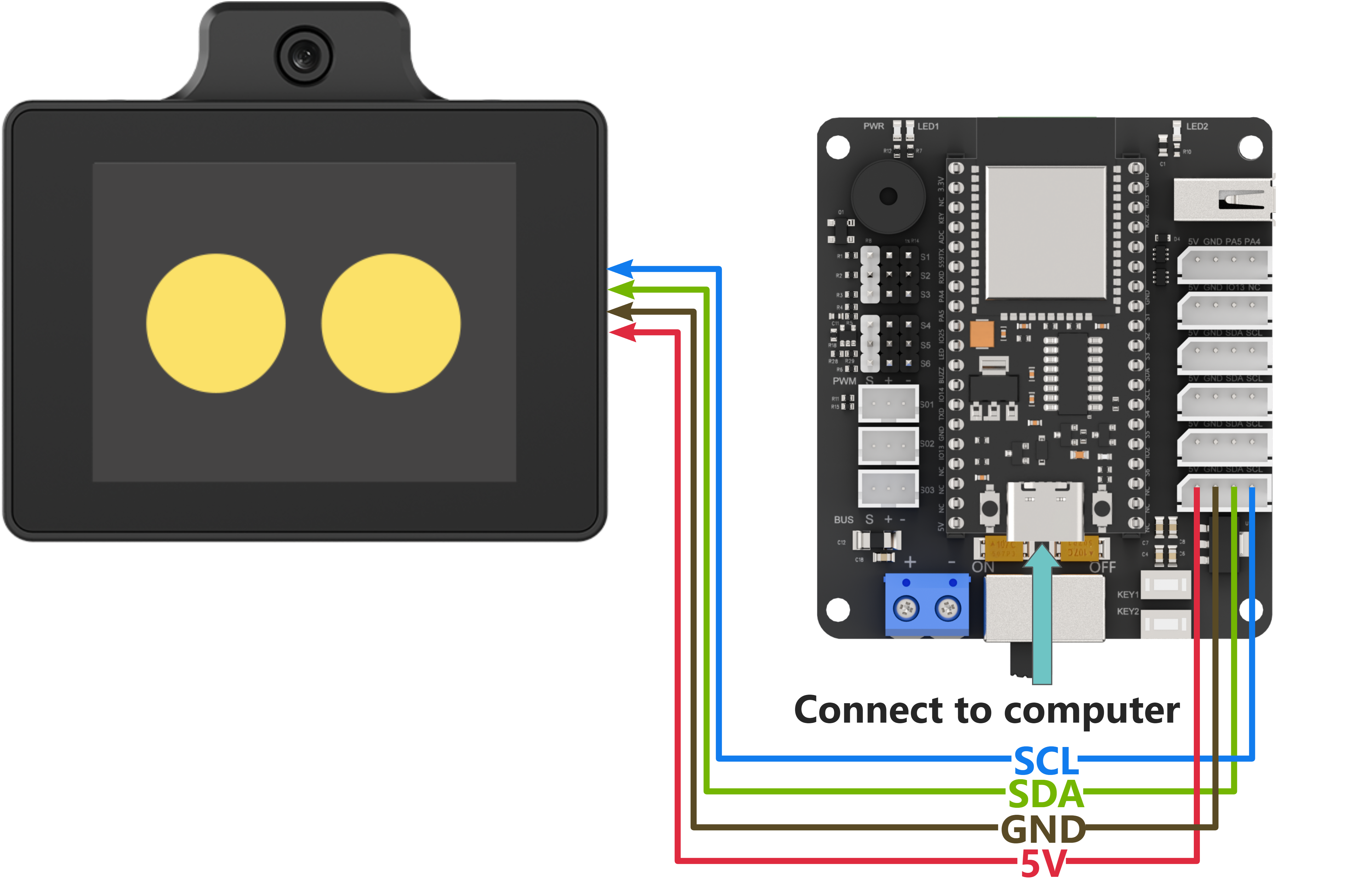
When wiring, connect the WonderLLM’s 5V, GND, SCL, and SDA pins to the ESP32 core board as shown in the diagram below:

The ESP32 core board can be used in combination with our open-source 6-channel servo controller, and the wiring to WonderLLM is shown in the diagram below:
Note
Before powering on, ensure that no metal objects are touching the controller. Otherwise, the exposed pins at the bottom of the board may cause a short circuit and damage the controller.
Program Download
ESP32 Program Download
Note
MicroPython supports multiple IDEs for downloading, such as Thonny and VScode. Relevant plugins need to be installed, and the specific operations should be searched independently. This example uses the “Hiwonder Python Editor” for downloading the program without installation.
If using ESP32, make sure that the MicroPython firmware is already installed on the ESP32 before downloading MicroPython. For firmware downloads, please visit the MicroPython official website. If using our ESP32 core board, flash the firmware file provided by Hiwonder, which located in “Appendix\13 ESP32 Core Board Firmware and Flashing Tool\02 ESP32 Firmware Flashing Tool”. For flashing instructions, please refer to the document in the same path.
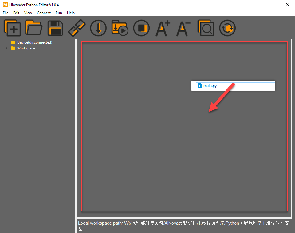
Open the Hiwonder Python Editor software
 which located in “Appendix/ 14 Hiwonder Python Editor”.
Drag the file “Appendix\07 ESP32 Program Files\01 ESP32 Speech Recognition Example\main.py” from this document’s path into the Hiwonder Python editor. Make sure to drag it into the red-framed area for it to be valid.
Click the connect button in the menu bar
 . After a successful connection, the icon will turn green
  .
.After successful connection, click the download button on the menu bar
 , to download the program to the ESP32. Wait for the prompt in the information interaction box below to indicate that the download is complete.
Note
After completing the above 4 steps, please drag the WonderLLM offline speech feature communication library into the editor, which located in “Appendix\07 ESP32 Program Files\01 ESP32 Speech Recognition Example\hw_esp32ASR_ctl.py”. Follow the same steps to import the library file into the ESP32. After downloading, click the reset icon on the interface  to reset the ESP32. The output information will be displayed in the output information bar below.
Test Case
This example uses the ESP32 development board to obtain the recognition result from the WonderLLM module and prints it out through the software terminal.
Project Outcome
Note
Before recognition, the module needs to hear “Hello Hiwonder” to wake up the module, after which it can perform recognition.
(1) When the WonderLLM module recognizes the go straight entry, it will respond with going straight, and the terminal will print go;
(2) When the WonderLLM module recognizes the backward entry, it will respond with going backward, and the terminal will print back;
(3) When the WonderLLM module recognizes the turn left entry, it will respond with turning left, and the terminal will print left;
(4) When the WonderLLM module recognizes the turn right entry, it will respond with turning right, and the terminal will print right;
(5) When the WonderLLM module recognizes the stop or halt entry, it will respond with received, and the terminal will print stop;

Program Brief Analysis
(1) The I2C bus protocol library machine.I2C, the time handling function library time, and the WonderLLM offline speech function communication library are imported.
#!/usr/bin/python3
# coding=utf8
import time
from machine import Pin, I2C
from hw_esp32ASR_ctl import ASRModule,ASR_CMDMAND,ASR_ANNOUNCER
(2) An object asr_module of the WonderLLM module class is created. During initialization, the I2C handle of the ESP32 is passed to establish a communication connection between the ESP32 bus and the module.
if __name__ == "__main__":
    iic = I2C(0, scl=Pin(23), sda=Pin(22), freq=100000)
    asr_module = ASRModule(iic)
(3) During the initialization of the ASRModule class, when the class is instantiated as an object, the passed I2C handle is stored in the internal bus member, and the specified module I2C address is also configured.
class ASRModule:
    def __init__(self,iic_handle):
        # Initialize I2C bus and device address
        self.bus = iic_handle  # Bind the I2C bus handle
        self.address = I2C_ADDR
        self.send = [0, 0]  # Initialize the array for sending data
(4) In this section, read the recognition result data stored in the module’s register. First create a function wire_read_data_array under the ASRModule class that reads data from the device via the I2C bus. The function requires the register address reg and the length of the data to be read, as shown below.
(5) Call the bus member of the ASRModule class and use its built-in readfrom_mem function to read the data from the device at each address.
(6) The third parameter of this function specifies the number of bytes to read. The return value is a list with a length equal to the number of bytes read.
(7) If there is a failure in the bus communication and data cannot be read, the system will throw an exception. Since the read_i2c_block_data function does not return any value, to maintain consistent output from the wire_read_data_array function, we need to output an empty list in the exception handling.
     def wire_read_data_array(self, reg, length):
        """
        Read byte array from the specified register
        :param reg: The register address
        :param length: The number of bytes to read
        :return: The byte array read from the register, or an empty array if the read fails
        """
        try:
            result = self.bus.readfrom_mem(self.address, reg, length)  # Read byte array from the device
            return result  # Return the read result
        except Exception as e:
            print(f"IIC_read_failed: {e}/r/n")
            return []  # Return an empty array if reading fails
(8) Next, use the rec_recognition() function under the ASRModule class to get the recognition result of the entry.
(9) In this function, call the wire_read_data_array function within the same class, and then use an if statement to check if the return value is an empty list. If the return value is an empty list, it indicates a failure in reading, and the function will return 0. Otherwise, it will return the recognition result.
    def rec_recognition(self):
        """
        Read the Recognized Results
        :return: # Recognition result, return 0 if reading fails
        """
        result = self.wire_read_data_array(ASR_RESULT_ADDR, 1)  # Read one byte from the result register
        if result:
            return result  # Return the read result
        return 0  # If no result, return 0
(10) In the main function, after the WonderLLM module class is instantiated, the asr_module.rec_recognition() function is called in a loop to continuously retrieve the data returned by the WonderLLM module.
    while True:
        recognition_result = asr_module.rec_recognition()
(11) When the go straight entry is recognized, it will return 0x01; when backward is recognized, it will return 0x02. Following this pattern, when a command word is recognized, the corresponding entry ID will be returned. The Raspberry Pi will print the corresponding semantic in English to the command-line terminal based on the returned entry ID. Then, the program will proceed to the next round of the loop.
(12) If no speech is recognized, 0x00 will be returned. In this case, the program will not perform any operation and will directly proceed to the next round of the loop.
        if recognition_result[0] != 0:
            if recognition_result[0] == 1:
                print("go")
            elif recognition_result[0] == 2:
                print("back")
            elif recognition_result[0] == 3:
                print("left")
            elif recognition_result[0] == 4:
                print("right")
            elif recognition_result[0] == 9:
                print("stop")
Note
For the detailed list of returned data, please refer to the “Command Word Broadcast Word Protocol List”.
4.12.2 ESP32 Speech Boradcast Example
Wiring Instructions
Note
MicroPython code can run on any microcontroller that supports MicroPython programming. This section uses Hiwonder ESP32 core board as an example.
When wiring, connect the WonderLLM’s 5V, GND, SCL, and SDA pins to the ESP32 core board as shown in the diagram below:
The ESP32 core board can be used in combination with our open-source 6-channel servo controller, and the wiring to WonderLLM is shown in the diagram below:
Note
Before powering on, ensure that no metal objects are touching the controller. Otherwise, the exposed pins at the bottom of the board may cause a short circuit and damage the controller.
Program Download
ESP32 Program Download
Note
MicroPython supports multiple IDEs for downloading, such as Thonny and VScode. Relevant plugins need to be installed, and the specific operations should be searched independently. This example uses the “Hiwonder Python Editor” for downloading the program without installation.
If using ESP32, make sure that the MicroPython firmware is already installed on the ESP32 before downloading MicroPython. For firmware downloads, please visit the MicroPython official website. If using our ESP32 core board, flash the firmware file provided by Hiwonder, which located in “Appendix\13 ESP32 Core Board Firmware and Flashing Tool\02 ESP32 Firmware Flashing Tool”. For flashing instructions, please refer to the document in the same path.
Open the Hiwonder Python Editor software
which located in “Appendix/ 14 Hiwonder Python Editor”.Drag the file “Appendix\07 ESP32 Program Files\01 ESP32 Speech Recognition Example\main.py” from this document’s path into the Hiwonder Python editor. Make sure to drag it into the red-framed area for it to be valid.
Click the connect button in the menu bar
. After a successful connection, the icon will turn green .After successful connection, click the download button on the menu bar
, to download the program to the ESP32. Wait for the prompt in the information interaction box below to indicate that the download is complete.
Note
After completing the above 4 steps, please drag the WonderLLM offline speech feature communication library into the editor, which located in “Appendix\07 ESP32 Program Files\01 ESP32 Speech Recognition Example\hw_esp32ASR_ctl.py”. Follow the same steps to import the library file into the ESP32. After downloading, click the reset icon on the interface to reset the ESP32. The output information will be displayed in the output information bar below.
Test Case
This example uses the Raspberry Pi development board to make the WonderLLM module continuously play speech, including both command word broadcast speech and general broadcast speech.
Project Outcome
The Raspberry Pi development board controls the WonderLLM module to broadcast the following messages every 5 seconds in sequence: going straight, turning left, recyclable, and hazardous waste.
Program Brief Analysis
(1) The I2C bus protocol library machine.I2C, the time handling function library time, and the WonderLLM offline speech function communication library are imported.
#!/usr/bin/python3
# coding=utf8
import time
from machine import Pin, I2C
from hw_esp32ASR_ctl import ASRModule,ASR_CMDMAND,ASR_ANNOUNCER
(2) An object asr_module of the WonderLLM module class is created. During initialization, the I2C handle of the ESP32 is passed to establish a communication connection between the ESP32 bus and the module.
if __name__ == "__main__":
    iic = I2C(0, scl=Pin(23), sda=Pin(22), freq=100000)
    asr_module = ASRModule(iic)
(3) During the initialization of the ASRModule class, when the class is instantiated as an object, the passed I2C handle is stored in the internal bus member, and the specified module I2C address is also configured.
class ASRModule:
    def __init__(self,iic_handle):
        # Initialize I2C bus and device address
        self.bus = iic_handle  # Bind the I2C bus handle
        self.address = I2C_ADDR
        self.send = [0, 0]  # Initialize the array for sending data
(4) Write the data of the entry to be played into the module’s register to start broadcasting. First, construct a function wire_write_data_array under the ASRModule class to send data to the device via the I2C bus. Pass the register address reg, the list val containing the data to be written, and the length length of the data to be written.
(5) Call the bus member under the ASRModule class and use its built-in writeto_mem function to write data to the register of the device at different addresses.
    def wire_write_data_array(self, reg, val, length):
        """
        Write byte array to the specified register
        :param reg: The register address
        :param val: The byte array to be written.
        :param length: The number of bytes to write
        :return: Return True if the write is successful, otherwise return False.
        """
        try:
            self.bus.writeto_mem(self.address, reg, bytes(val[:length]))  # Send byte array to the specified register of the device
            return True  # Write successful
        except Exception :
            return False  # Write failed, return False
(6) Further, we will use the speak() function under the ASRModule class to implement the writing of entry data. The entry type cmd and entry ID are written sequentially into the send list under the ASRModule class. Finally, the wire_write_data_array function in the same class is called, passing the send list as the data list parameter to perform the write operation.
    def speak(self, cmd, id):
        """
        Send speak command to the device
        :param cmd: Command byte
        :param id: ID of the speech
        """
        self.send[0] = cmd  # Set the first element of the send array to the command
        self.send[1] = id  # Set the second element of the send array to the ID
        self.wire_write_data_array(ASR_SPEAK_ADDR, self.send, 2)  # Send command and ID to the specified register
(7) After instantiating the WonderLLM module class in the main function, define a list to store the data of the entries to be played. Each element of the list is a tuple, and each tuple contains the type and ID data of the entry to be played.
(8) ASR_ANNOUNCER value 0xFF indicates that the function type to be written is a general broadcast speech. Write 0x01 to the register address ANNOUNCER, where data 0x01 corresponds to the speech entry recyclable waste and data 0x03 corresponds to the speech entry hazardous waste.
(9) ASR_ANNOUNCER value 0x00 indicates that the function type to be written is a general broadcast speech. Write 0x01 to the register address ANNOUNCER, where data 0x01 corresponds to the speech entry recyclable waste and data 0x03 corresponds to the speech entry hazardous waste.
    # Define the broadcast content and its corresponding ID
    announcements = [
        (ASR_CMDMAND, 1),  # Going forward
        (ASR_CMDMAND, 3),  # Turning left
        (ASR_ANNOUNCER, 1),  # Recyclable waste
        (ASR_ANNOUNCER, 3)   # Hazardous waste
    ]
(10) Subsequently, the main function enters a while loop that continuously executes the internal code. Inside the while loop, a for loop is nested, iterating over each tuple in the announcements list. Each tuple’s elements are unpacked into cmd and id variables.
(11) Finally, the speak function of the asr_module object is called, passing cmd and id as the entry type and ID number to the function. This will cause the module to broadcast the corresponding entry. The program then sleeps for 5 seconds before reading the next entry’s information from the list. After completing the list iteration, the program goes back to the while loop and starts iterating the list again, repeating the cycle.
    while True:
        for cmd, id in announcements:
            asr_module.speak(cmd, id)
            time.sleep(5)
Note
The detailed list of returned data, please refer to the “Command Word Broadcast Word Protocol List”.
4.12. 3 ESP32 Module Address Modification Example
Wiring Instructions
Note
MicroPython code can run on any microcontroller that supports MicroPython programming. This section uses Hiwonder ESP32 core board as an example.
When wiring, connect the WonderLLM’s 5V, GND, SCL, and SDA pins to the ESP32 core board as shown in the diagram below:
The ESP32 core board can be used in combination with our open-source 6-channel servo controller, and the wiring to WonderLLM is shown in the diagram below:
Note
Before powering on, ensure that no metal objects are touching the controller. Otherwise, the exposed pins at the bottom of the board may cause a short circuit and damage the controller.
Program Download
ESP32 Program Download
Note
MicroPython supports multiple IDEs for downloading, such as Thonny and VScode. Relevant plugins need to be installed, and the specific operations should be searched independently. This example uses the “Hiwonder Python Editor” for downloading the program without installation.
If using ESP32, make sure that the MicroPython firmware is already installed on the ESP32 before downloading MicroPython. For firmware downloads, please visit the MicroPython official website. If using our ESP32 core board, flash the firmware file provided by Hiwonder, which located in “Appendix\13 ESP32 Core Board Firmware and Flashing Tool\02 ESP32 Firmware Flashing Tool”. For flashing instructions, please refer to the document in the same path.
Open the Hiwonder Python Editor software
which located in “Appendix/ 14 Hiwonder Python Editor”.Drag the file “Appendix\07 ESP32 Program Files\01 ESP32 Speech Recognition Example\main.py” from this document’s path into the Hiwonder Python editor. Make sure to drag it into the red-framed area for it to be valid.
Click the connect button in the menu bar
. After a successful connection, the icon will turn green .After successful connection, click the download button on the menu bar
, to download the program to the ESP32. Wait for the prompt in the information interaction box below to indicate that the download is complete.
Note
After completing the above 4 steps, please drag the WonderLLM offline speech feature communication library into the editor, which located in “Appendix\07 ESP32 Program Files\01 ESP32 Speech Recognition Example\hw_esp32ASR_ctl.py”. Follow the same steps to import the library file into the ESP32. After downloading, click the reset icon on the interface to reset the ESP32. The output information will be displayed in the output information bar below.
Test Case
This example demonstrates how to use ESP32 Development Board to repeatedly switch the I2C device address of the WonderLLM module and control the module to perform voice broadcasting via I2C communication using the new address.
Project Outcome
(1) ESP32 Development Board controls the WonderLLM module to switch its device address to 0x34, then uses this I2C address to sequentially play the voice broadcasting Going straight and Recyclable waste.
(2) Next, switch the WonderLLM module’s device address to 0x33, then uses this I2C address to sequentially perform the voice broadcasting Going straight and Recyclable waste.
(3) This process repeats in a loop.

Program Brief Analysis
(1) The I2C bus protocol library machine.I2C, the time handling function library time, and the WonderLLM offline speech function communication library are imported.
#!/usr/bin/python3
# coding=utf8
import time
from machine import Pin, I2C
from hw_esp32ASR_ctl import ASRModule,ASR_CMDMAND,ASR_ANNOUNCER
(2) An object asr_module of the WonderLLM module class is created. During initialization, the I2C handle of the ESP32 is passed to establish a communication connection between the ESP32 bus and the module.
if __name__ == "__main__":
    iic = I2C(0, scl=Pin(23), sda=Pin(22), freq=100000)
    asr_module = ASRModule(iic)
(3) During the initialization of the ASRModule class, when the class is instantiated as an object, the passed I2C handle is stored in the internal bus member, and the specified module I2C address is also configured.
class ASRModule:
    def __init__(self,iic_handle):
        # Initialize I2C bus and device address
        self.bus = iic_handle  # Bind the I2C bus handle
        self.address = I2C_ADDR
        self.send = [0, 0]  # Initialize the array for sending data
(4) Write the data of the entry to be played into the module’s register to start broadcasting. First, construct a function wire_write_data_array under the ASRModule class to send data to the device via the I2C bus. Pass the register address reg, the list val containing the data to be written, and the length length of the data to be written.
(5) Call the bus member under the ASRModule class and use its built-in writeto_mem function to write data to the register of the device at different addresses.
    def wire_write_data_array(self, reg, val, length):
        """
        Write byte array to the specified register
        :param reg: The register address
        :param val: The byte array to be written.
        :param length: The number of bytes to write
        :return: Return True if the write is successful, otherwise return False.
        """
        try:
            self.bus.writeto_mem(self.address, reg, bytes(val[:length]))  # Send byte array to the specified register of the device
            return True  # Write successful
        except Exception :
            return False  # Write failed, return False
(6) Furthermore, use the ChangeAddr() method provided by the ASRModule class to perform the actual address update operation. The program will first check the validity of the input parameter, specifically whether the new address new_addr belongs to one of the two allowed types.
(7) After confirming the validity of the new address, the program places new_addr into a list and then calls the wire_write_data_array function from the same class.
(8) The list is passed as the data buffer, ASR_IIC_ADDR_CHANGE_ADDR(0x03) as the target register address, and 1 as the number of bytes to write, thereby completing the data write operation.
(9) Since the address member of the ASRModule class still retains the module’s original I2C address at this stage, the Raspberry Pi establishes communication using the old address to transmit the new one.
(10) Once the data is successfully written, the I2C device address on the module is updated accordingly. Subsequently, the address member of the ASRModule class is updated to the new I2C address, completing the synchronization of the I2C address within the controller program.
    def ChangeAddr(self, new_addr):
        """
        Send I2C address modification command to the device.
        :new_addr: New I2C address, with valid values being 0x33 or 0x34.
        """
        if new_addr == 0x33 or new_addr == 0x34:
            self.wire_write_data_array(ASR_IIC_ADDR_CHANGE_ADDR, [new_addr],1)
            self.address = new_addr
            return 1
        else:
            return 0
(11) After instantiating the WonderLLM module class in the main function, define a list to store the data of the entries to be played. Each element of the list is a tuple, and each tuple contains the type and ID data of the entry to be played.
(12) The value of ASR_ANNOUNCER being 0x00 indicates that the function type to be written is the command word broadcast speech. Writing 0x01 to the register address ANNOUNCER triggers the broadcast of the corresponding entry: Going straight.
(13) ASR_ANNOUNCER value 0xFF indicates that the function type to be written is a general broadcast speech. Writing 0x01 to the ANNOUNCER register in this case corresponds to broadcasting the message: Recyclable waste.
    # Define the broadcast content and its corresponding ID
    announcements = [
        (ASR_CMDMAND, 1),  # Going forward
        (ASR_ANNOUNCER, 1),  # Recyclable waste
    ]
(14) Then, the main function enters a while loop that repeatedly executes the following actions. First, it calls the sleep function to delay for 1 second. Then, it prints a string to notify that the module’s I2C address will soon be changed. The ChangeAddr function of the asr object is called with the new I2C address 0x34 passed as an argument.
(15) The ChangeAddr function will check the validity of the new address parameter to ensure it is one of the specified values, 0x33 or 0x34. If valid, it will return 1 and begin communication to send the data.
(16) An if statement is used to check whether the ChangeAddr function executed successfully. If so, the program delays for 100 ms to allow the new address configuration to take effect. It then communicates with the module using the new I2C address to trigger voice broadcasting of the entry.
        time.sleep(1)

        print("now,asr module's I2C Address is 0x34!")
        if(asr_module.ChangeAddr(0x34)):
            print("Success!")
            time.sleep(0.1)

            for cmd, id in announcements:
                asr_module.speak(cmd, id)
                time.sleep(2)

        else:
            print("Fail!")
(17) Next, the program proceeds to change the I2C address of the WonderLLM module back to 0x33 and uses this address to control broadcasting again. The process is nearly identical to the one described above and will not be elaborated here.
Note
The detailed list of returned data, please refer to the “Command Word Broadcast Word Protocol List”.
4.13 Communication with STM32 Controller
4.13.1 STM32F407 Speech Recognition Example
Preparation
Wiring Instruction
When wiring, the 5V, GND, SCL, and SDA pins of the WonderLLM module need to be connected to the STM32 development board. Using our Ros Robot Controller v1.2 as an example. The wiring diagram is shown below:
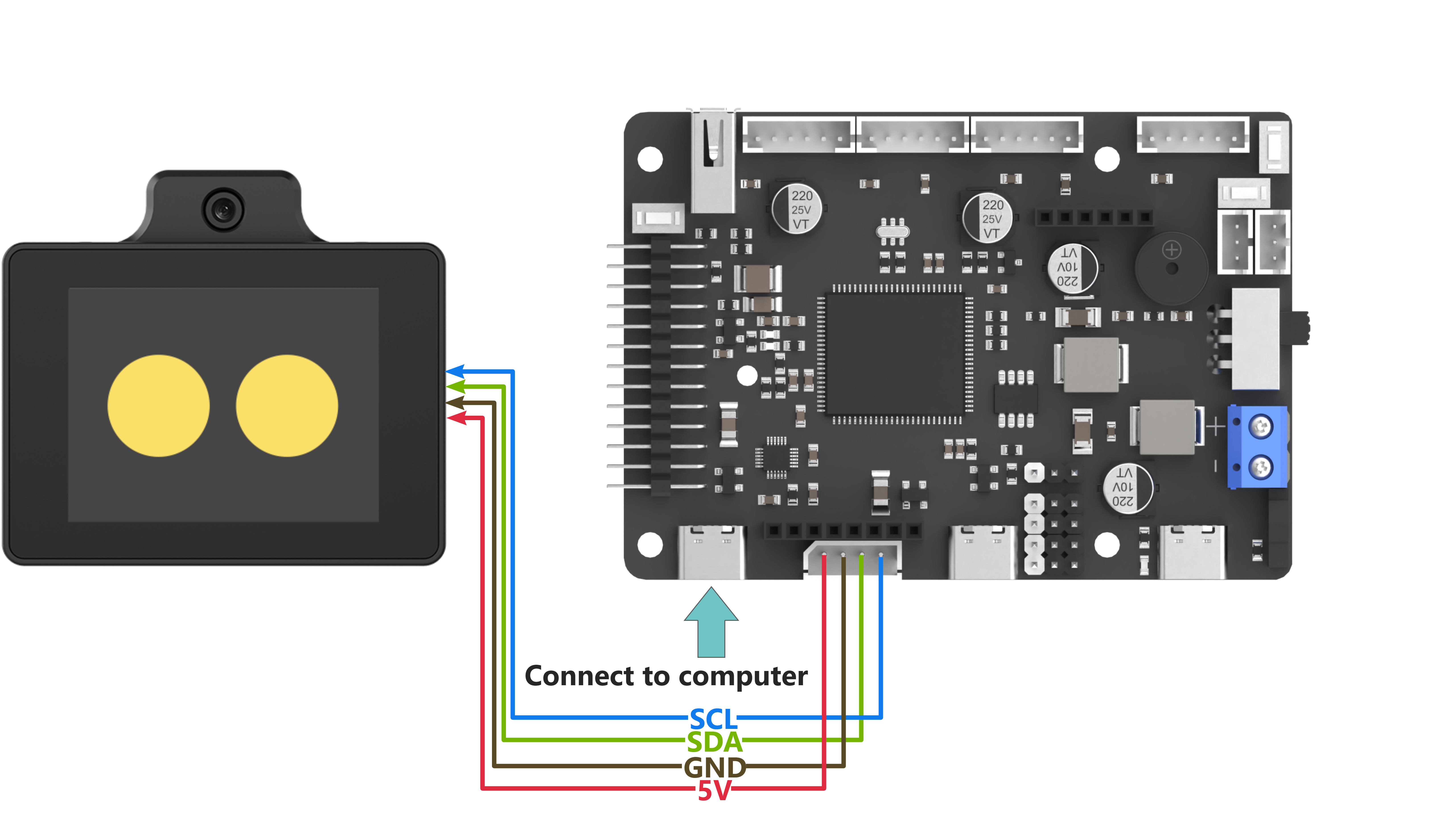
Note
Before powering on, ensure that no metal objects are touching the controller. Otherwise, the exposed pins at the bottom of the board may cause a short circuit and damage the controller.
Program Download
STM32 Program Download
(1) Connect the Type-C cable to the Type-C port on the STM32 controller. Make sure to use the UART1 port as shown in the figure below and plug the other end into the USB port of the computer.
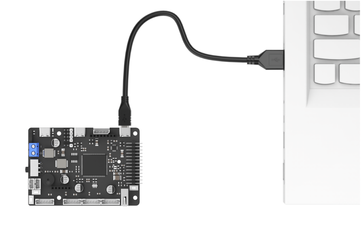
(2) Open the Device Manager on the computer and check the COM port number under the “Ports” section.
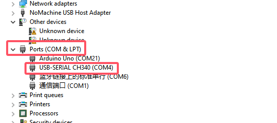
(3) Launch the ATK-XISP software, select the corresponding COM port, and set the baud rate to 115200.
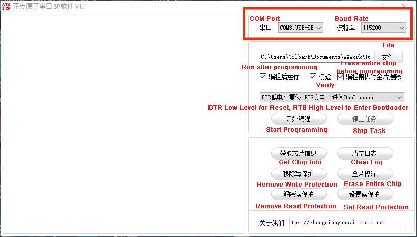
(4) Configure the software as shown in the image below.
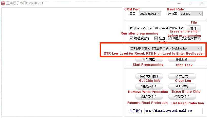
(5) Click the File button on the software interface, select the file “Appendix\08 STM32 Program/ 01 STM32 Speech Recognition Example\STM32F407_ASR_recognition/MDK-ARM/RosRobotControllerM4/RosRobotControllerM4.hex” for programming.
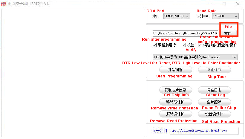
(6) Click the Start button on the page to flash the generated hex file onto the STM32 controller. Wait for the flashing process to complete successfully.
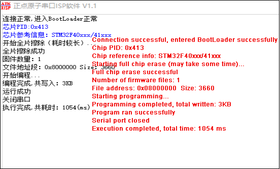
Test Case
This example uses the STM32F407 development board to obtain the recognition result from the WonderLLM module and prints it out through uart1.
Project Outcome
Note
Before recognition, the module needs to hear “Hello Hiwonder” to wake up the module, after which it can perform recognition.
(1) When the WonderLLM module recognizes the go straight entry, it will respond with going straight, and the serial port will print go;
(2) When the WonderLLM module recognizes the go backward entry, it will respond with going backward, and the serial port will print back;
(3) When the WonderLLM module recognizes the turn left entry, it will respond with turning left, and the serial port will print left;
(4) When the WonderLLM module recognizes the turn right entry, it will respond with turning right, and the serial port will print right;
(5) When the WonderLLM module recognizes the stop entry, it will respond with stop, and the serial port will print stop.
Program Brief Analysis
Note
The WonderLLM module STM32 example runs on the FreeRTOS system, with the app_task task provided to execute custom logic. The main.c file is only used for initializing system peripherals and starting the RTOS system. The logic related to the WonderLLM module is placed in the app_task callback function app_task_entry (located in app.c).
(1) The program imports controller communication-related libraries to enable communication with the WonderLLM module.
#include "cmsis_os2.h"
#include "global.h"
(2) Define macros for the I2C address of the WonderLLM module, as well as for registers, command words, and speech phrases.
#define ASR_ADDR  0x34

// The storage location for recognition results. By continuously reading the value at this address, it is possible to determine whether speech has been recognized. Different values correspond to different speech.
#define ASR_RESULT_ADDR   100
#define ASR_SPEAK_ADDR    110

#define ASR_CMDMAND    0x00
#define ASR_ANNOUNCER  0xFF
(3) In the main function, a result variable is created to store the recognition result. The recognition result is obtained through the HAL_I2C_Mem_Read() function.
        uint8_t result = 0;
        HAL_I2C_Mem_Read(&hi2c2, ASR_ADDR << 1, ASR_RESULT_ADDR, I2C_MEMADD_SIZE_8BIT, &result, 1, 0xFF);
(4) When the go straight entry is recognized, it will return 0x01; when backward is recognized, it will return 0x02. Similarly, recognizing any entry will return the corresponding entry ID number.
Note
For the detailed list of returned data, please refer to the “Command Word Broadcast Word Protocol List”.
        if(result != 0)
        {
            if(result == 0x01)
            {
              printf("go");
            }else if(result == 0x02)
            {
              printf("back");
4.13.2 STM32F407 Speech Boradcast Example
Preparation
Wiring Instruction
When wiring, the 5V, GND, SCL, and SDA pins of the WonderLLM module need to be connected to the STM32 development board. Using our Ros Robot Controller v1.2 as an example. The wiring diagram is shown below:
Note
Before powering on, ensure that no metal objects are touching the controller. Otherwise, the exposed pins at the bottom of the board may cause a short circuit and damage the controller.
Program Download
STM32 Program Download
(1) Connect the Type-C cable to the Type-C port on the STM32 controller. Make sure to use the UART1 port as shown in the figure below and plug the other end into the USB port of the computer.
(2) Open the Device Manager on the computer and check the COM port number under the “Ports” section.
(3) Launch the ATK-XISP software, select the corresponding COM port, and set the baud rate to 115200.
(4) Configure the software as shown in the image below.
(5) Click the File button on the software interface, select the file “Appendix\08 STM32 Program/ 02 STM32 Speech Broadcast Example\STM32F407_ASR_announce/MDK-ARM/RosRobotControllerM4/RosRobotControllerM4.hex” for programming.
(6) Click the Start Programming button on the page to flash the generated hex file onto the STM32 controller. Wait for the flashing process to complete successfully.
Test Case
This example uses the STM32F407 development board to control the WonderLLM module loop through speech playback.
Project Outcome
The STM32F407 development board controls the WonderLLM module to broadcast the following messages every 5 seconds in sequence: going straight, turning left, recyclable, and hazardous waste.
Program Brief Analysis
Note
The WonderLLM module STM32 example runs on the FreeRTOS system, with the app_task task provided to execute custom logic. The main.c file is only used for initializing system peripherals and starting the RTOS system. The logic related to the WonderLLM module is placed in the app_task callback function app_task_entry (located in app.c).
(1) The program imports controller communication-related libraries to enable communication with the WonderLLM module.
#include "cmsis_os2.h"
#include "global.h"
(2) Define macros for the I2C address of the WonderLLM module, as well as for registers, command words, and speech phrases.
#define ASR_ADDR  0x34

// The storage location for recognition results. By continuously reading the value at this address, it is possible to determine whether speech has been recognized. Different values correspond to different speech.
#define ASR_RESULT_ADDR   100
#define ASR_SPEAK_ADDR    110

#define ASR_CMDMAND    0x00
#define ASR_ANNOUNCER  0xFF
(3) In the main function, data is written to the WonderLLM module by calling the HAL_I2C_Mem_Write() function. This function has two parameters: the first element of the speak_cmd array is the register address for the command word, and the second element is the value corresponding to the broadcast speech. ASR_CMDMAND is a macro definition with a value of 0x00, indicating that the type of function to be written is a command word. First, write 0x01 to the register address ASR_CMDMAND, which corresponds to the broadcast statement going straight. The data 0x03 corresponds to turning left in the data list.
        uint8_t speak_cmd[2] = {ASR_CMDMAND , 0x01};
        HAL_I2C_Mem_Write(&hi2c2, ASR_ADDR << 1, ASR_SPEAK_ADDR, I2C_MEMADD_SIZE_8BIT, speak_cmd, 2, 0xFF);
		// Command word broadcast speech: "Going forward"
        osDelay(5000);

        speak_cmd[1] = 0x03;
        HAL_I2C_Mem_Write(&hi2c2, ASR_ADDR << 1, ASR_SPEAK_ADDR, I2C_MEMADD_SIZE_8BIT, speak_cmd, 2, 0xFF);
		// Command word broadcast speech: "Turning left"
        osDelay(5000);
(4) The speak_ann array’s first element is the register address for the broadcast phrase, and the second element corresponds to the value of the broadcast phrase. When ASR_ANNOUNCER equals 0xFF, it indicates that the function type to be written is a broadcast phrase. Write 0x01 to the register address ANNOUNCER, corresponding to the broadcast phrase “Recyclable waste”, and 0x03 corresponds to the broadcast phrase “Hazardous waste”.
        uint8_t speak_ann[2] = {ASR_ANNOUNCER , 0x01};
        HAL_I2C_Mem_Write(&hi2c2, ASR_ADDR << 1, ASR_SPEAK_ADDR, I2C_MEMADD_SIZE_8BIT, speak_ann, 2, 0xFF);
		// Broadcast phrase: Recyclable waste
        osDelay(5000);

        speak_ann[1] = 0x03;
        HAL_I2C_Mem_Write(&hi2c2, ASR_ADDR << 1, ASR_SPEAK_ADDR, I2C_MEMADD_SIZE_8BIT, speak_ann, 2, 0xFF);
		// Broadcast phrase: Hazardous waste
        osDelay(5000);
Note
The detailed list of returned data, please refer to the “Command Word Broadcast Word Protocol List”.
4.13. 3 STM32F407 Module Address Modification Example
Preparation
Wiring Instruction
When wiring, the 5V, GND, SCL, and SDA pins of the WonderLLM module need to be connected to the STM32 development board. Using our Ros Robot Controller v1.2 as an example. The wiring diagram is shown below:
Note
Before powering on, ensure that no metal objects are touching the controller. Otherwise, the exposed pins at the bottom of the board may cause a short circuit and damage the controller.
Program Download
STM32 Program Download
(1) Connect the Type-C cable to the Type-C port on the STM32 controller. Make sure to use the UART1 port as shown in the figure below and plug the other end into the USB port of the computer.
(2) Open the Device Manager on the computer and check the COM port number under the “Ports” section.
(3) Launch the ATK-XISP software, select the corresponding COM port, and set the baud rate to 115200.
(4) Configure the software as shown in the image below.
(5) Click the File button on the software interface, select the file “Appendix\08 STM32 Program/ 03 STM32 Module Address Modification Example\STM32F407_ASR_IICaddr_change/MDK-ARM/RosRobotControllerM4/RosRobotControllerM4.hex” for programming.
(6) Click the Start Programming button on the page to flash the generated hex file onto the STM32 controller. Wait for the flashing process to complete successfully.
Test Case
This example demonstrates how to use STM32 Development Board to repeatedly switch the I2C device address of the WonderLLM module and control the module to perform voice broadcasting via I2C communication using the new address.
Project Outcome
(1) STM32F407 Development Board controls the WonderLLM module to switch its device address to 0x34, then uses this I2C address to sequentially play the voice broadcasting Going straight and Recyclable waste.
(2) Next, switch the WonderLLM module’s device address to 0x33, then uses this I2C address to sequentially perform the voice broadcasting Going straight and Recyclable waste.
(3) This process repeats in a loop.
Program Brief Analysis
Note
The WonderLLM module STM32 example runs on the FreeRTOS system, with the app_task task provided to execute custom logic. The main.c file is only used for initializing system peripherals and starting the RTOS system. The logic related to the WonderLLM module is placed in the app_task callback function app_task_entry (located in app.c).
(1) The program imports controller communication-related libraries to enable communication with the WonderLLM module.
#include "cmsis_os2.h"
#include "global.h"
(2) Define macros for the I2C address of the WonderLLM module, as well as for registers, command words, and speech phrases.
// The storage location for recognition results. By continuously reading the value at this address, it is possible to determine whether speech has been recognized. Different values correspond to different speech.
#define ASR_RESULT_ADDR            100
#define ASR_SPEAK_ADDR             110
#define ASR_IIC_ADDR_CHANGE_ADDR   3

#define ASR_CMDMAND    0x00
#define ASR_ANNOUNCER  0xFF
In the main function, two arrays are initialized for voice broadcasting: speak_cmd and speak_ann. In speak_ann, element 1 represents the phrase type, and element 2 indicates the index of the speech phrase to be broadcast. In speak_cmd, element 1 represents the command type, and element 2 corresponds to the index of the command phrase to be spoken.
(4) IIC_Addr_now represents the current I2C address of the WonderLLM module, and IIC_Addr_new represents the expected updated I2C address of the WonderLLM module.
/* User entry function */
void app_task_entry(void *argument)
{
    /* Declare external handles */
    uint8_t speak_cmd[2] = {ASR_CMDMAND , 0x01};
    uint8_t speak_ann[2] = {ASR_ANNOUNCER , 0x01};
    uint8_t IIC_Addr_now;
    uint8_t IIC_Addr_new;
		osDelay(500);
    printf("start");
(5) Inside the main loop, the program first prints a string to indicate the upcoming address change. Call the HAL_I2C_Mem_Write() function. Using the current module I2C address IIC_Addr_now, write the new 1-byte address IIC_Addr_new to the ASR_IIC_ADDR_CHANGE_ADDR register of the WonderLLM module.
(6) Once the module receives the new address, it begins switching its I2C address. The program then updates the IIC_Addr_now variable to reflect the new address IIC_Addr_new. A delay of 100 ms is inserted to allow the module to complete the address switch internally.
    for(;;) {
		printf("now,asr module's I2C Address is 0x34!");
		IIC_Addr_now = 0x34;
		IIC_Addr_new = 0x33;
		// Write the new address to the module's I2C address register.
        HAL_I2C_Mem_Write(&hi2c2, IIC_Addr_now << 1, ASR_IIC_ADDR_CHANGE_ADDR, I2C_MEMADD_SIZE_8BIT, &IIC_Addr_new, 1, 0xFF);
        IIC_Addr_now = IIC_Addr_new;
		osDelay(100);
(7) Call the HAL_I2C_Mem_Write() function. Using the updated current module I2C address IIC_Addr_now, write the 2-byte broadcast data to the ASR_SPEAK_ADDR broadcast register of the WonderLLM module. The module will receive commands and perform the corresponding broadcast operation with the new I2C address.
        HAL_I2C_Mem_Write(&hi2c2, IIC_Addr_now << 1, ASR_SPEAK_ADDR, I2C_MEMADD_SIZE_8BIT, speak_cmd, 2, 0xFF);
		// Command word broadcast speech: "Going forward"
        osDelay(2000);
        HAL_I2C_Mem_Write(&hi2c2, IIC_Addr_now << 1, ASR_SPEAK_ADDR, I2C_MEMADD_SIZE_8BIT, speak_ann, 2, 0xFF);
		// Broadcast phrase: Recyclable waste
        osDelay(2000);
(8) Afterward, the program proceeds to switch the module’s I2C address to 0x33 using a similar process, which will not be elaborated here.
Note
The detailed list of returned data, please refer to the “Command Word Broadcast Word Protocol List”.
4.14 Communication with Raspberry Pi Controller
4.14.1 Raspberry Pi Speech Recognition Example
Preparation
Wiring Instruction
The connection between the WonderLLM module and the Raspberry Pi controller is as shown below:
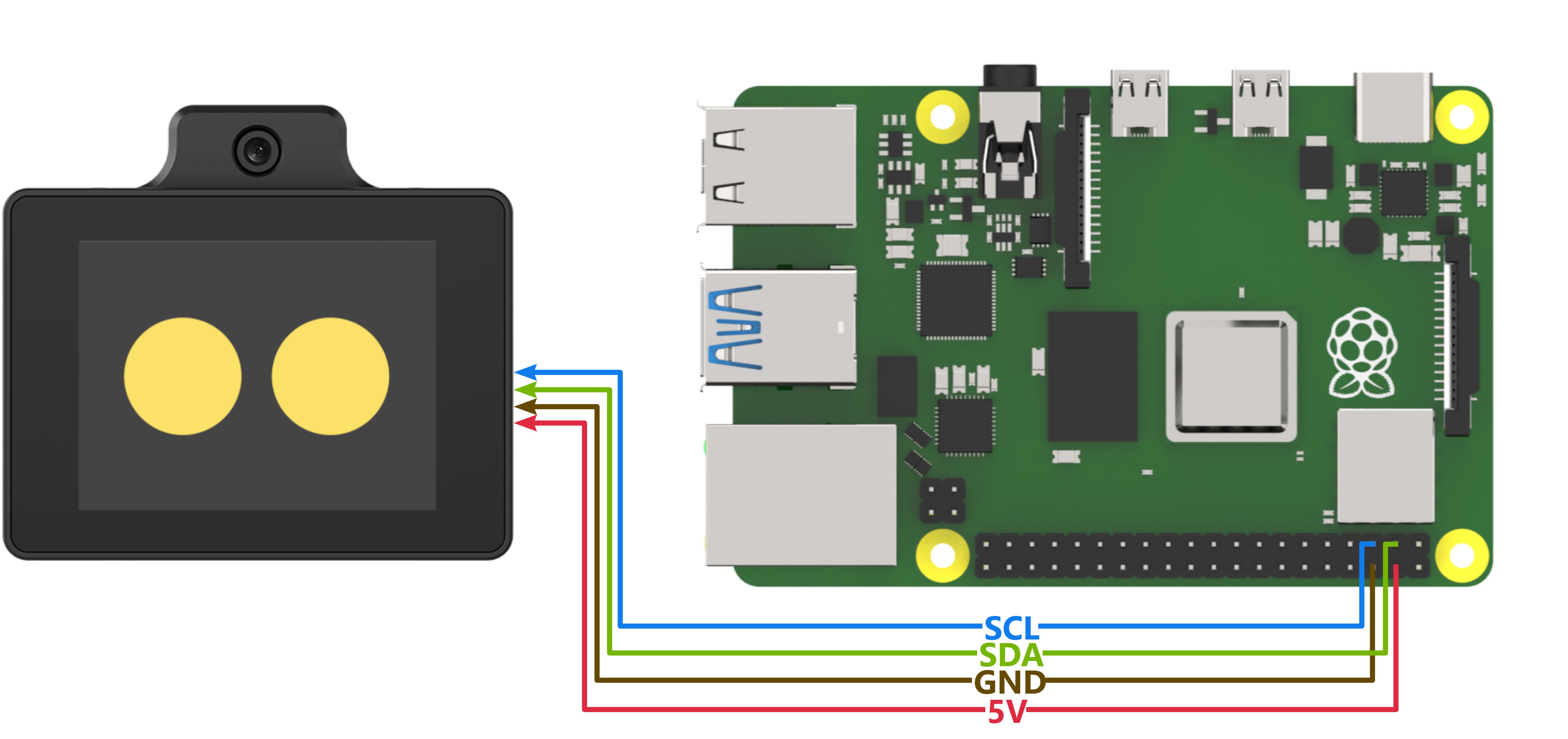
Program Download
Importing and Running the Program
(1) First, power on the Raspberry Pi and connect to it from the PC using VNC or other methods.
(2) Upload the example file from “Appendix\09 Raspberry Pi Program Files\01 Raspberry Pi Speech Recognition Example” in the same directory as this document to any path on the Raspberry Pi using SSH or other methods.
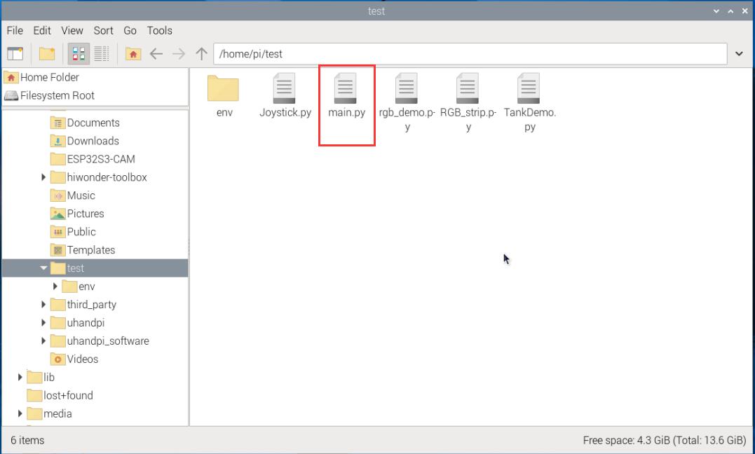
(3) In the menu bar, click: “TOOLS” – “Open Current Folder in Terminal” to open the command line in the current directory.
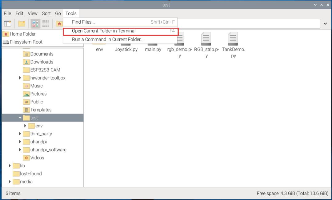
(4) Enter the following command in the command line to run the program:
python main.py
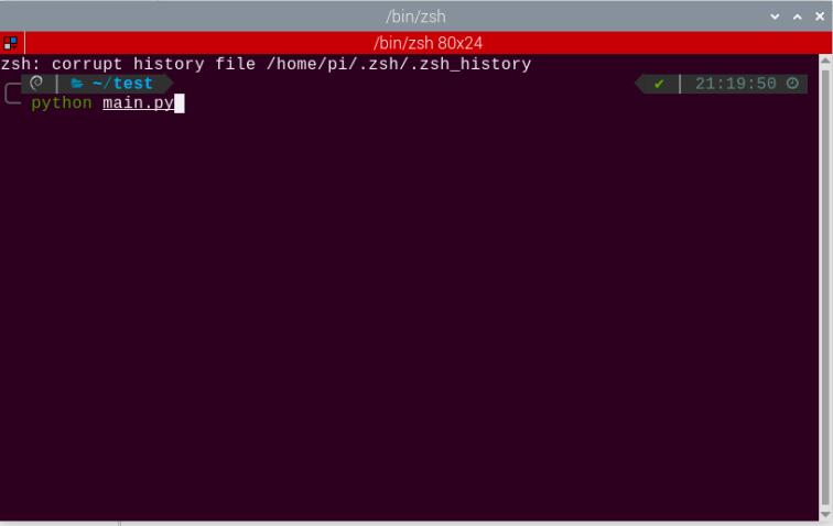
Test Case
This example uses the Raspberry Pi development board to obtain the recognition results from the WonderLLM module and prints them out through the command-line terminal.
Project Outcome
Note
Before recognition, the module needs to hear “Hello Hiwonder” to wake up the module, after which it can perform recognition.
(1) When the WonderLLM module recognizes the go straight entry, it will respond with going straight, and the command-line terminal will print go;
(2) When the WonderLLM module recognizes the backward entry, it will respond with going backward, and the command-line terminal will print back;
(3) When the WonderLLM module recognizes the turn left entry, it will respond with turning left, and the command-line terminal will print left;
(4) When the WonderLLM module recognizes the turn right entry, it will respond with turning right, and the command-line terminal will print right;
(5) When the WonderLLM module recognizes the stop or halt entry, it will respond with received, and the command-line terminal will print stop;
Program Brief Analysis
(1) Import the I2C bus protocol library smbus and the time handling function library time for communication with the WonderLLM module.
#!/usr/bin/python3
# coding=utf8
import smbus
import time
(2) Create an object asr_module under the WonderLLM module class, and a variable recognition_result for receiving the recognition results from the WonderLLM module. The I2C address of the WonderLLM module must be provided during initialization to establish communication between the Raspberry Pi bus and the module.
if __name__ == "__main__":
    asr_module = ASRModule(I2C_ADDR)
(3) The internal members of the ASRModule class, when initialized (i.e., when the class is instantiated as an object), will default to instantiating an object bus of the SMBus class from the smbus library. This allows communication to be established through the Raspberry Pi’s I2C bus 1, and the I2C address passed during initialization will be specified.
class ASRModule:
    def __init__(self,address, bus=1):
        # Initialize I2C bus and device address
        self.bus = smbus.SMBus(bus)  # Use I2C bus 1
        self.address = address  # I2C address of the device
        self.send = [0, 0]  # Initialize the list for sending data
(4) In this section, read the recognition result data stored in the module’s register. First create a function wire_read_data_array under the ASRModule class that reads data from the device via the I2C bus. The function requires the register address reg and the length of the data to be read, as shown below.
(5) Call the member bus (the SMBus class object) under the ASRModule class and use its built-in read_i2c_block_data function to read the data from the registers at the device’s address.
(6) The third parameter of this function specifies the number of bytes to read. The return value is a list with a length equal to the number of bytes read. The list does not require any processing and can be directly used as the output of the wire_read_data_array function.
(7) If there is a IOError failure in the bus communication and data cannot be read, the system will throw an exception. Since the read_i2c_block_data function does not return any value, to maintain consistent output from the wire_read_data_array function, we need to output an empty list in the exception handling.
    def wire_read_data_array(self, reg, length):
        """
        Read byte list from the specified register
        :param reg: The register address
        :param length: The number of bytes to read
        :return: The byte list read from the register, or an empty list if the read fails
        """
        try:
            result = self.bus.read_i2c_block_data(self.address, reg, length) # Read byte list from the device
            return result  # Return the read result
        except IOError:
            return []  # Read failed, return an empty list
(8) Next, use the rec_recognition() function under the ASRModule class to get the recognition result of the entry.
(9) In this function, call the wire_read_data_array function within the same class, and then use an if statement to check if the return value is an empty list. If the return value is an empty list, it indicates a failure in reading, and the function will return 0. Otherwise, it will return the recognition result.
    def rec_recognition(self):
        """
        Read the Recognized Results
        :return: Recognition result, return 0 if the read fails.
        """
        result = self.wire_read_data_array(ASR_RESULT_ADDR, 1)  # Read one byte from the result register
        if result:
            return result  # Return the read result
        return 0  # If no result, return 0
(10) In the main function, after the WonderLLM module class is instantiated, the asr_module.rec_recognition() function is called in a loop to continuously retrieve the data returned by the WonderLLM module.
    while True:
        recognition_result = asr_module.rec_recognition()
(11) When the go straight entry is recognized, it will return 0x01; when backward is recognized, it will return 0x02. Following this pattern, when a command word is recognized, the corresponding entry ID will be returned. The Raspberry Pi will print the corresponding semantic in English to the command-line terminal based on the returned entry ID. Then, the program will proceed to the next round of the loop.
(12) If no speech is recognized, 0x00 will be returned. In this case, the program will not perform any operation and will directly proceed to the next round of the loop.
        if recognition_result[0] != 0:
            if recognition_result[0] == 1:
                print("go")
            elif recognition_result[0] == 2:
                print("back")
            elif recognition_result[0] == 3:
                print("left")
            elif recognition_result[0] == 4:
                print("right")
            elif recognition_result[0] == 9:
                print("stop")
Note
For the detailed list of returned data, please refer to the “Command Word Broadcast Word Protocol List”.
4.14.2 Raspberry Pi Speech Broadcast Example
Preparation
Wiring Instruction
The connection between the WonderLLM module and the Raspberry Pi controller is as shown below:
Program Download
Importing and Running the Program
(1) First, power on the Raspberry Pi and connect to it from the PC using VNC or other methods.
(2) Upload the example file from “Appendix\09 Raspberry Pi Program Files\02 Raspberry Pi Speech Broadcast Example” in the same directory as this document to any path on the Raspberry Pi using SSH or other methods.
(3) In the menu bar, click: “TOOLS” – “Open Current Folder in Terminal” to open the command line in the current directory.
(4) Enter the following command in the command line to run the program:
python main.py
Test Case
This example uses the Raspberry Pi development board to make the WonderLLM module continuously play speech, including both command word broadcast speech and general broadcast speech.
Project Outcome
The Raspberry Pi development board controls the WonderLLM module to broadcast the following messages every 5 seconds in sequence: going straight, turning left, recyclable, and hazardous waste.
Program Brief Analysis
(1) Import the I2C bus protocol library smbus and the time handling function library time for communication with the WonderLLM module.
#!/usr/bin/python3
# coding=utf8
import smbus
import time
(2) Create an object asr_module under the WonderLLM module class. The I2C address of the WonderLLM module must be provided during initialization to establish communication between the Raspberry Pi bus and the module.
if __name__ == "__main__":
    asr_module = ASRModule(I2C_ADDR)
(3) The internal members of the ASRModule class, when initialized (i.e., when the class is instantiated as an object), will default to instantiating an object bus of the SMBus class from the smbus library. This allows communication to be established through the Raspberry Pi’s I2C bus 1, and the I2C address passed during initialization will be specified.
class ASRModule:
    def __init__(self,address, bus=1):
        # Initialize I2C bus and device address
        self.bus = smbus.SMBus(bus)  # Use I2C bus 1
        self.address = address  # I2C address of the device
        self.send = [0, 0]  # Initialize the array for sending data
(4) Write the data of the entry to be played into the module’s register to start broadcasting. First, construct a function wire_write_data_array under the ASRModule class to send data to the device via the I2C bus. Pass the register address reg, the list val containing the data to be written, and the length length of the data to be written.
(5) Call the member bus (the SMBus class object) under the ASRModule class and use its built-in write_i2c_block_data function to write the data from the registers at the device’s address.
    def wire_write_data_array(self, reg, val, length):
        """
        Write byte array to the specified register
        :param reg: The register address
        :param val: The byte array to be written.
        :param length: The number of bytes to write
        :return: Return True if the write is successful, otherwise return False.
        """
        try:
            self.bus.write_i2c_block_data(self.address, reg, val[:length])   # Send byte array to the specified register of the device
            return True  # Write successful
        except IOError:
            return False  # Write failed, return False
(6) Further, we will use the speak() function under the ASRModule class to implement the writing of entry data. The entry type cmd and entry ID are written sequentially into the send list under the ASRModule class. Finally, the wire_write_data_array function in the same class is called, passing the send list as the data list parameter to perform the write operation.
    def speak(self, cmd, id):
        """
        Send speak command to the device
        :param cmd: Command byte
        :param id: ID of the speech
        """
        self.send[0] = cmd  # Set the first element of the send array to the command
        self.send[1] = id  # Set the second element of the send array to the ID
        self.wire_write_data_array(ASR_SPEAK_ADDR, self.send, 2)  # Send command and ID to the specified register
(7) After instantiating the WonderLLM module class in the main function, define a list to store the data of the entries to be played. Each element of the list is a tuple, and each tuple contains the type and ID data of the entry to be played.
(8) ASR_ANNOUNCER value 0xFF indicates that the function type to be written is a general broadcast speech. Write 0x01 to the register address ANNOUNCER, corresponding to the broadcast phrase “Recyclable waste”, and 0x03 corresponds to the broadcast phrase “Hazardous waste”.
(9) ASR_ANNOUNCER value 0x00 indicates that the function type to be written is a general broadcast speech. Write 0x01 to the register address ANNOUNCER, corresponding to the broadcast phrase “Recyclable waste”, and 0x03 corresponds to the broadcast phrase “Hazardous waste”.
    # Define the broadcast content and its corresponding ID
    announcements = [
        (ASR_CMDMAND, 1),  # Going forward
        (ASR_CMDMAND, 3),  # Turning left
        (ASR_ANNOUNCER, 1),  # Recyclable waste
        (ASR_ANNOUNCER, 3)   # Hazardous waste
    ]
(10) Subsequently, the main function enters a while loop that continuously executes the internal code. Inside the while loop, a for loop is nested, iterating over each tuple in the announcements list. Each tuple’s elements are unpacked into cmd and id variables.
(11) Finally, the speak function of the asr_module object is called, passing cmd and id as the entry type and ID number to the function. This will cause the module to broadcast the corresponding entry. The program then sleeps for 5 seconds before reading the next entry’s information from the list. After completing the list iteration, the program goes back to the while loop and starts iterating the list again, repeating the cycle.
    while True:
        for cmd, id in announcements:
            asr_module.speak(cmd, id)
            time.sleep(5)
Note
The detailed list of returned data, please refer to the “Command Word Broadcast Word Protocol List”.
4.14.3 Raspberry Pi Module Address Modification Example
Preparation
Wiring Instruction
sThe connection between the WonderLLM module and the Raspberry Pi controller is as shown below:
Program Download
Importing and Running the Program
(1) First, power on the Raspberry Pi and connect to it from the PC using VNC or other methods.
(2) Upload the example file from “Appendix\09 Raspberry Pi Program Files\03 Raspberry Pi Module Address Modification Example” in the same directory as this document to any path on the Raspberry Pi using SSH or other methods.
(3) In the menu bar, click: “TOOLS” – “Open Current Folder in Terminal” to open the command line in the current directory.
(4) Enter the following command in the command line to run the program:
python main.py
Test Case
This example demonstrates how to use the Raspberry Pi development board to repeatedly switch the I2C device address of the WonderLLM module and control the module to perform voice broadcasting via I2C communication using the new address.
Project Outcome
(1) The Raspberry Pi development board controls the WonderLLM module to switch its device address to 0x34, then uses this I2C address to sequentially play the voice broadcasting Going straight and Recyclable waste.
(2) Next, switch the WonderLLM module’s device address to 0x33, then uses this I2C address to sequentially perform the voice broadcasting Going straight and Recyclable waste.
(3) This process repeats in a loop.
Program Brief Analysis
(1) Import the I2C bus protocol library smbus and the time handling function library time for communication with the WonderLLM module.
#!/usr/bin/python3
# coding=utf8
import smbus
import time
(2) Create an object asr_module under the WonderLLM module class. The default I2C address of the WonderLLM module must be provided during initialization to establish communication between the Raspberry Pi bus and the module.
if __name__ == "__main__":
    asr_module = ASRModule(I2C_ADDR)
(3) The internal members of the ASRModule class, when initialized (i.e., when the class is instantiated as an object), will default to instantiating an object bus of the SMBus class from the smbus library. This allows communication to be established through the Raspberry Pi’s I2C bus 1, and the I2C address passed during initialization will be specified.
class ASRModule:
    def __init__(self,address, bus=1):
        # Initialize I2C bus and device address
        self.bus = smbus.SMBus(bus)  # Use I2C bus 1
        self.address = address  # I2C address of the device
        self.send = [0, 0]  # Initialize the array for sending data
(4) Write the new I2C device address to the I2C address register, so that the module is mounted on the I2C bus with this address. First, it is necessary to construct a function wire_write_data_array under the ASRModule class to handle sending data to the device via the I2C bus, as shown in the figure below. The function requires the register address reg, the list val to store the data to be written, and the length of the data length to be passed as arguments.
(5) Call the member bus (the SMBus class object) under the ASRModule class and use its built-in write_i2c_block_data function to write the data from the registers at the device’s address.
    def wire_write_data_array(self, reg, val, length):
        """
        Write byte array to the specified register
        :param reg: The register address
        :param val: The byte array to be written.
        :param length: The number of bytes to write
        :return: Return True if the write is successful, otherwise return False.
        """
        try:
            self.bus.write_i2c_block_data(self.address, reg, val[:length])   # Send byte array to the specified register of the device
            return True  # Write successful
        except IOError:
            return False  # Write failed, return False
(6) Furthermore, use the ChangeAddr() method provided by the ASRModule class to perform the actual address update operation. The program will first check the validity of the input parameter, specifically whether the new address new_addr belongs to one of the two allowed types.
(7) After confirming the validity of the new address, the program places new_addr into a list and then calls the wire_write_data_array function from the same class.
(8) The list is passed as the data buffer, ASR_IIC_ADDR_CHANGE_ADDR(0x03) as the target register address, and 1 as the number of bytes to write, thereby completing the data write operation.
(9) Since the address member of the ASRModule class still retains the module’s original I2C address at this stage, the Raspberry Pi establishes communication using the old address to transmit the new one.
(10) Once the data is successfully written, the I2C device address on the module is updated accordingly. Subsequently, the address member of the ASRModule class is updated to the new I2C address, completing the synchronization of the I2C address within the controller program.
    def ChangeAddr(self, new_addr):
        """
        Send I2C address modification command to the device.
        :new_addr: New I2C address, with valid values being 0x33 or 0x34.
        """
        if new_addr == 0x33 or new_addr == 0x34:
            self.wire_write_data_array(ASR_IIC_ADDR_CHANGE_ADDR, [new_addr],1)
            self.address = new_addr
            return 1
        else:
            return 0
(11) After instantiating the WonderLLM module class in the main function, define a list to store the data of the entries to be played. Each element of the list is a tuple, and each tuple contains the type and ID data of the entry to be played.
(12) The value of ASR_ANNOUNCER being 0x00 indicates that the function type to be written is the command word broadcast speech. Writing 0x01 to the register address ANNOUNCER triggers the broadcast of the corresponding entry: Going straight.
(13) ASR_ANNOUNCER value 0xFF indicates that the function type to be written is a general broadcast speech. Writing 0x01 to the ANNOUNCER register in this case corresponds to broadcasting the message: Recyclable waste.
    # Define the broadcast content and its corresponding ID
    announcements = [
        (ASR_CMDMAND, 1),  # Going forward
        (ASR_ANNOUNCER, 1),  # Recyclable waste
    ]
(14) Then, the main function enters a while loop that repeatedly executes the following actions. First, it calls the sleep function to delay for 1 second. Then, it prints a string to notify that the module’s I2C address will soon be changed. The ChangeAddr function of the asr object is called with the new I2C address 0x34 passed as an argument.
(15) The ChangeAddr function will check the validity of the new address parameter to ensure it is one of the specified values, 0x33 or 0x34. If valid, it will return 1 and begin communication to send the data.
(16) An if statement is used to check whether the ChangeAddr function executed successfully. If so, the program delays for 100 ms to allow the new address configuration to take effect. It then communicates with the module using the new I2C address to trigger voice broadcasting of the entry.
        time.sleep(1)

        print("now,asr module's I2C Address is 0x34!")
        if(asr_module.ChangeAddr(0x34)):
            print("Success!")
            time.sleep(0.1)

            for cmd, id in announcements:
                asr_module.speak(cmd, id)
                time.sleep(2)

        else:
            print("Fail!")
(17) Next, the program proceeds to change the I2C address of the WonderLLM module back to 0x33 and uses this address to control broadcasting again. The process is nearly identical to the one described above and will not be elaborated here.
Note
The detailed list of returned data, please refer to the “Command Word Broadcast Word Protocol List”.
4.15 Communication with the micro:bit Host
Note
The micro:bit host does not currently support the modification of the WonderLLM I2C address.
4.15.1 Import the WonderLLM Extension Package
In the programming page, click the Extensions section in the tab selection area.
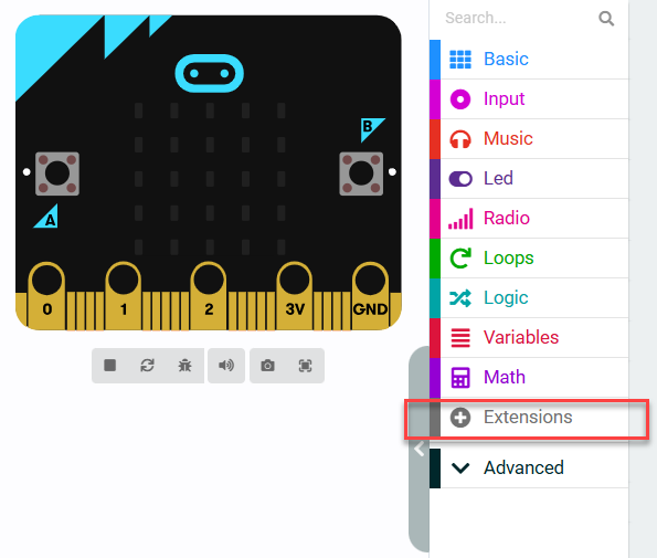
In the popup window, enter the extension package URL: https://github.com/Hiwonder/WonderEcho
After entering the link, click the search icon or press the Enter key, then click wonderecho to successfully add the extension.
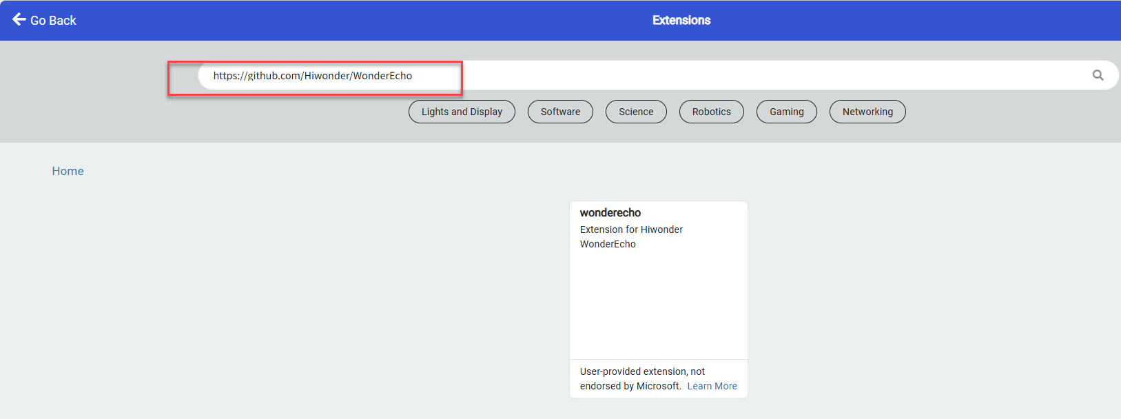
After the addition is complete, the interface will automatically return to the programming page. Wait for the loading to finish, then the program panel will display the newly added extension package. Click the wonderecho tab to expand it.
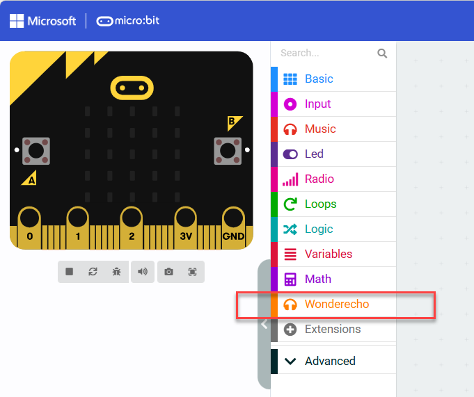
4.15.2 micro:bit Speech Recognition Example
Preparation
Wiring Instruction
The connection between the WonderLLM module and the micro:bit expansion board is as shown below:
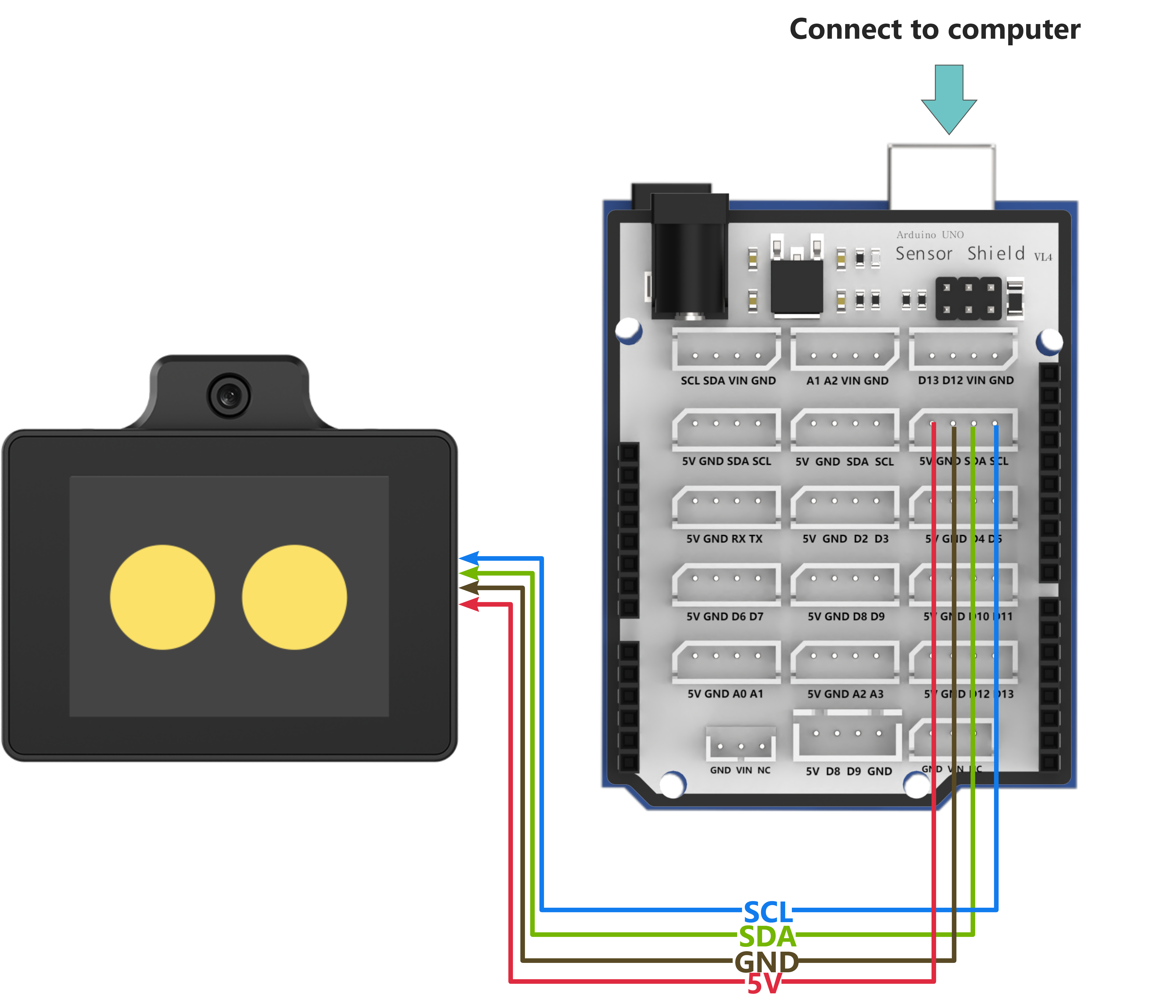
Note
Before powering on, ensure that no metal objects are touching the controller. Otherwise, the exposed pins at the bottom of the board may cause a short circuit and damage the controller.
micro: bit Program Download
(1) Click the icon in the lower-left corner of the interface  . Then click Connect Device and follow the on-screen instructions to connect the micro:bit mainboard.
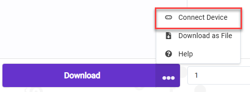
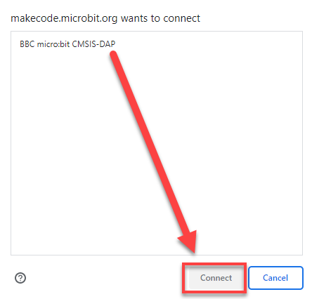
(2) Click the Download button in the bottom-left corner to flash the program.

(3) After the download is complete, the indicator light will stop flashing rapidly and remain steadily lit. At the same time, a download completion message will appear on the programming interface.

Test Case
Project Outcome
Note
Before recognition, the module needs to hear “Hello Hiwonder” to wake up the module, after which it can perform recognition.
(1) When the WonderLLM module recognizes the go straight entry, it will respond with going straight, and the serial port will print go;
(2) When the WonderLLM module recognizes the backward entry, it will respond with going backward, and the serial port will print back;
(3) When the WonderLLM module recognizes the turn left entry, it will respond with turning left, and the serial port will print left;
(4) When the WonderLLM module recognizes the turn right entry, it will respond with turning right, and the serial port will print right;
(5) When the WonderLLM module recognizes the stop or halt entry, it will respond with received, and the serial port will print stop;
Program Brief Analysis
(1) Initialize by redirecting the serial port to USB for communication with the computer via USB.

(2) Create an infinite loop that continuously reads the speech recognition result ID, and sends different string commands via the serial port based on the different ID values.
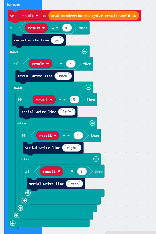
4.15.3 micro:bit Speech Recognition Example
Preparation
Wiring Instruction
The connection between the WonderLLM module and the micro:bit expansion board is as shown below:
Note
Before powering on, ensure that no metal objects are touching the controller. Otherwise, the exposed pins at the bottom of the board may cause a short circuit and damage the controller.
micro: bit Program Download
(1) Click the icon in the lower-left corner of the interface . Then click Connect Device and follow the on-screen instructions to connect the micro:bit mainboard.
(2) Click the Download button in the bottom-left corner to flash the program.
(3) After the download is complete, the indicator light will stop flashing rapidly and remain steadily lit. At the same time, a download completion message will appear on the programming interface.
Test Case
This example uses the micro:bit development board to make the WonderLLM module loop through speech playback.
Project Outcome
The WonderLLM module to broadcast the following messages every 5 seconds in sequence: going straight, turning left, recyclable, and hazardous waste.
Program Brief Analysis
In the loop function, set up the module to play the pre-recorded phrases.