2. Arduino Development Tutorial

2.1 Preparation
2.1.1 Wiring Instructions
In this section, a 4-pin cable is connected to pins A2 and A3 on the Arduino expansion board for demonstration purposes. Refer to the diagram below:

If you don’t have the Arduino expansion board, you could directly connect the sensor to the Arduino board using DuPont wires. The connection diagram is shown below:

Note
When using our lithium battery, ensure that the battery leads are connected correctly: red wire to +, black wire to –, and then connected to the DC input port.
If the battery leads are not connected to the lithium battery, do not connect them directly to each other. This may cause a short circuit due to reversed polarity.
Before powering on, make sure no metal objects are in contact with the controller. Otherwise, the exposed pins on the underside of the board may cause a short circuit and permanently damage the controller.
2.1.2 Environment Configuration
Install the Arduino IDE on your computer. The installation package can be found under: Appendix-> Arduino Installation Package.
For detailed instructions on how to use the Arduino IDE, please refer to the corresponding directory.
2.2 Test Cases
This test case displays the readings from the light sensor in the terminal window. The sensitivity of the light sensor can be controlled by configuring a threshold value.
2.2.1 Program Download
Connect the Arduino UNO development board with the expansion board to the computer using a USB cable. Launch the Arduino IDE, go to File → New in the toolbar, and import the program from the same directory as this tutorial.
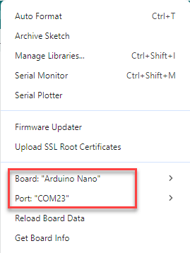
Select the correct development board and port (the ports shown below are for reference only; use the actual connected port). Compile the program and upload it to the board.
Once the program has been uploaded successfully, click
 , open the Serial Monitor and set the baud rate to 9600. Monitor the output to observe the sensor readings.
2.2.2 Program Outcome
Use the light sensor to measure ambient light intensity. When the photodiode is covered, the sensor reading exceeds 900, above the threshold; LED1 turns off, and the Serial Monitor displays 1. When uncovered, the reading drops below the threshold, LED1 turns on, and the Serial Monitor displays 0.

2.2.3 Program Analysis
Define Interfaces
#define Photosensitive A2  // The ADC pin of the light sensor is connected to A2 on the control board.
#define Photo A3  // The OUT pin of the light sensor is connected to A3 on the control board.
uint16_t brightness;
uint16_t bright;
First, the interfaces for the light sensor are defined, with the ADC and OUT pins connected to A2 and A3, respectively. The variables brightness and bright store the ADC reading and the digital output value.
Serial Port Initialization
void setup()
{
 Serial.begin(9600);  //It is primarily used to print data during debugging; this program does not use it.
 pinMode(Photosensitive, INPUT);
 pinMode(Photo, INPUT);
}
After initializing the serial port, the input mode for the two pins is configured.
Loop Execution
void loop()
{
 brightness = analogRead(Photosensitive);  //0-1023
 bright = digitalRead(Photo);
 Serial.print("ADC:");
 Serial.print(brightness);
 Serial.print(" OUT:");
 Serial.println(bright);
}
Within the loop() function, data is continuously acquired and processed. The analogRead() function reads the ADC value from pin A2 and stores it in the brightness variable, ranging from 0 to 1023.
The digitalRead() function reads the digital input from pin A3 and assigns it to the bright variable, representing a high or low logic level.The sampled results are then printed, allowing observation of how the ADC and digital output change with varying light intensity.