4. Multiple Controller Communication Tutorial
4.1 Master-Slave Device Communication Principles
4.1.1 Introduction
This section provides detailed information about the master-slave relationship between the voice recognition module and various devices (such as Arduino, STM32) during communication. It explains how the voice recognition module functions as a subordinate device, communicating with other devices, which act as master devices to control the module.
In this chapter, the voice recognition module is primarily used as a subordinate device, utilizing the I2C communication protocol to transmit data to other devices.
4.1.2 Master-Slave Relationship
Voice Recognition Module Function
(1) Receiving and Parsing Signals from the Master Device
The module waits for an I2C signal interrupt. When data is received through I2C, the module calls the corresponding function based on the register address information provided by the I2C signal.
(2) Data processing and feedback: When the module receives a command to read a register, it triggers the corresponding function to send the recognized data back to the master device.
Master Device Functions
(1) Sending Commands
The master device is responsible for sending read data commands to the voice recognition module.
(2) Control Coordination
The master device manages the entire system, ensuring there are no communication or operational conflicts between the voice recognition module and other devices, thus maintaining system stability.
(3) Data Reception
When reading data, the master device sends the read command and waits to receive the status information data from the voice recognition module. It then parses the received data packet to extract the relevant information.
4.1.3 I2C Device Address and Register
The address of the I2C slave device for the WonderEcho voice interaction module is 0x34.
| Register | Function |
|---|---|
| 0x64 (Register Address) | This register stores the recognized voice results, with a 1-byte value. (If no recognition occurs, the result will be 0x00.) |
| 0x6E (Register Address) | This register is used to set the ID for broadcasting, with a 2-byte value. The first byte can be either 0x00 or 0xFF: 0x00 represents the command word broadcasting type. 0xFF represents the normal broadcasting type. The second byte represents the ID number. |
Due to the large number of entries, the corresponding types and ID numbers can be found in the protocol documentation.
{Note} The master device and the module can have separate power sources, but they must share a common ground to ensure stable communication and voltage levels.
4.1.4 I2C Device Address Modification and Address Register
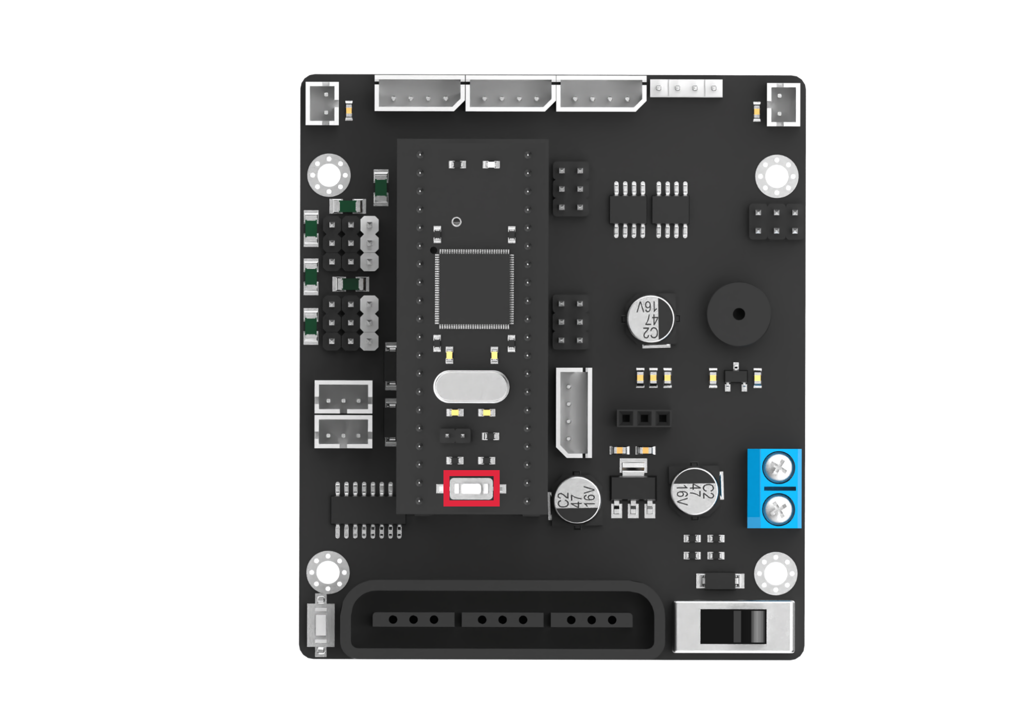
When using multiple types of modules or sensors, the I2C address of the voice interaction module may conflict with that of other modules (e.g., our voice interaction module and the four-channel motor driver module). In the new version of the voice interaction module, an I2C address modification function has been added. You can determine the version of your module based on the following indicators:
| Module Behavior | Conclusion |
|---|---|
| After powering on or pressing the RST button, the STA indicator flashes quickly 3 times and then slowly once | New version |
| After powering on or pressing the RST button, the STA indicator slowly flashes once | Old version |
Relevant Registers:
| Register | Function |
|---|---|
| 0x03 | Register used to set the module's I2C address. The host must send 1 byte of data. (Permissible values: 0x33 / 0x34. Other values are invalid. The default value is 0x34.) |
Note
Once a valid value is successfully written to this register, the module will begin switching its internal I2C slave address. At this point, the STA indicator will flash quickly 3 times, indicating a successful address change.
Switching the internal I2C slave address takes some time. If a command is sent to the voice interaction module using the new I2C address immediately after the change, the module may not respond properly. To ensure normal communication, please wait at least 100ms before attempting to communicate with the module using the new address.
4.2 ID Analysis for Command Word & Broadcast Statement
Open the Command Word Broadcasting Protocol List file located in the same directory as this lesson. This file contains the communication protocol for CI1302 and I2C chips.
The protocol begins with 0xAA, 0x55 and ends with 0xFB. The two bytes in between represent the function type and the ID number, respectively.
4.2.1 Functional Command Word
The first section of the protocol document consists of functional command word for voice recognition. These command words are used to configure the voice interaction module and typically do not require any modifications.

4.2.2 Command Entries
Below are examples of recognized command words. The two middle bytes in each command are 0x00 and the ID number, respectively. For example:
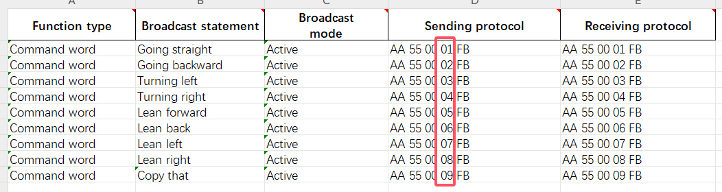
Example:
When the voice interaction module recognizes the “Move Forward” command, it responds with “Moving forward.” The main controller can then read 0x01 (a single byte) from the recognition result register (0x64). This byte corresponds to the 4th byte in the “Move Forward” command protocol.
4.2.3 Broadcast Statement
The broadcast phrases will not be played automatically. They must be triggered by the main controller through I2C settings. (The broadcast phrases for command entries can also be played.)
To trigger a broadcast, the main controller writes two bytes to the broadcast register (0x6E) via I2C: one byte for the type and one byte for the ID number. The voice interaction module will then broadcast the corresponding phrase. There are two types of broadcasts:
0x00 for command entry phrases (as defined in section 2: Command Entries).
0xFF for general broadcast phrases.
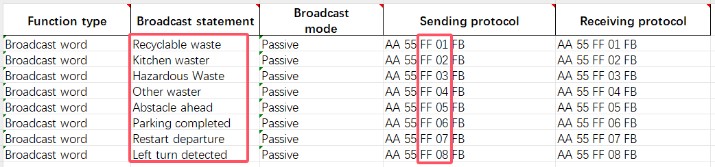
Example:
To broadcast “Kitchen Waste,” the main controller needs to write 0xFF 0x02 to the broadcast register (0x6E) via I2C. The voice interaction module will then broadcast “Kitchen Waste.”
4.3 Arduino Communication
4.3.1 Arduino Voice Recognition
Getting Ready
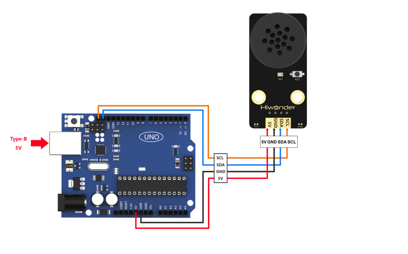
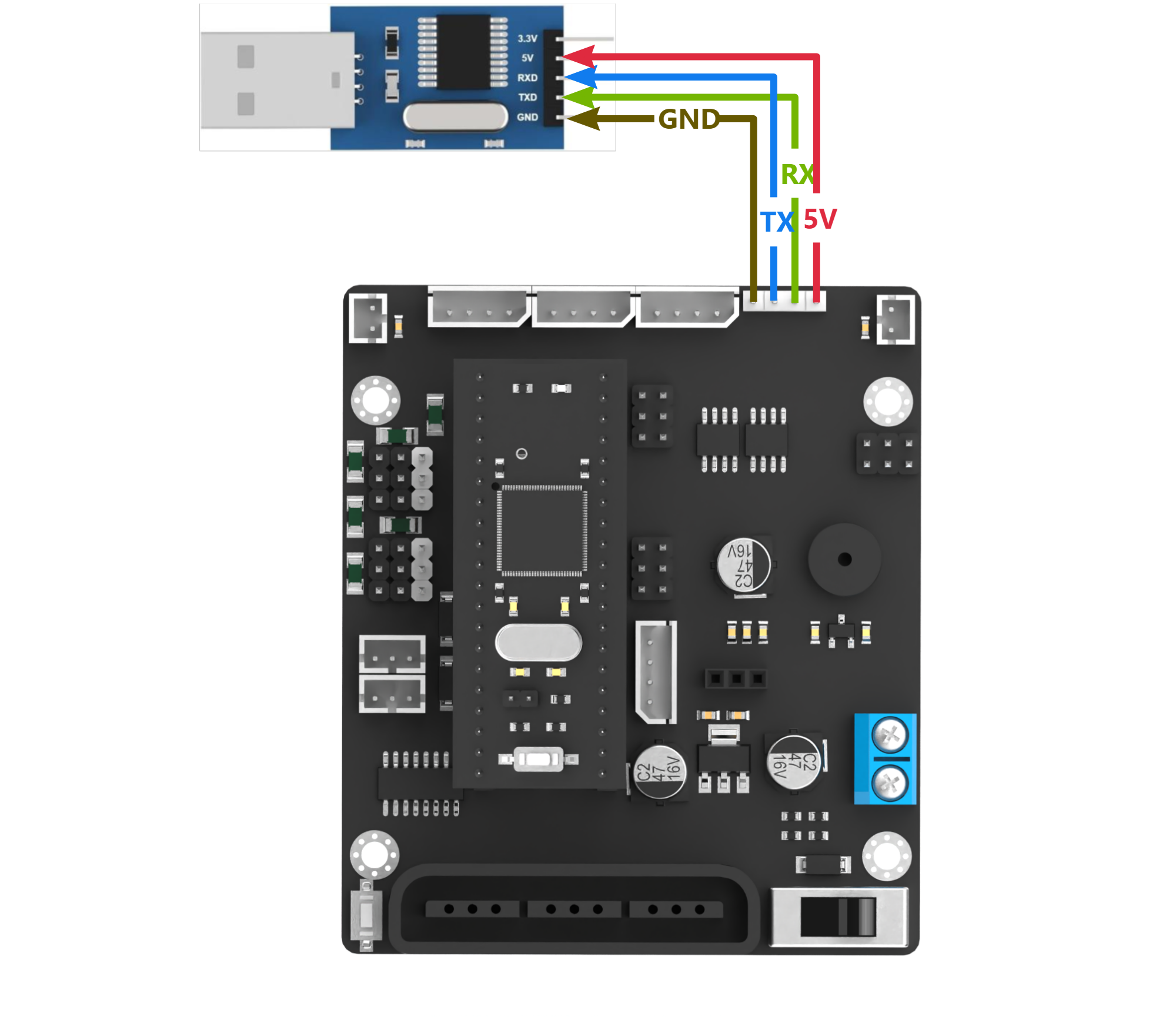
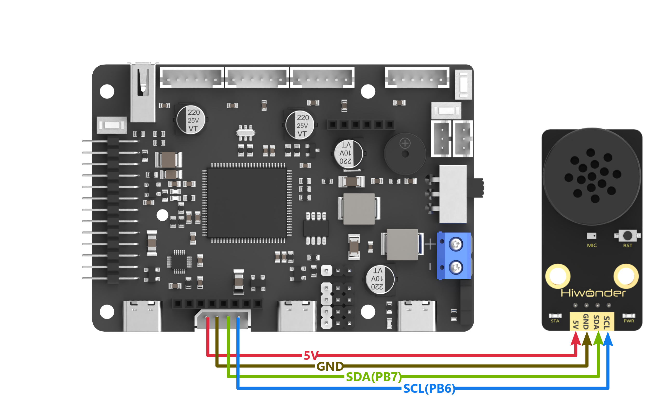
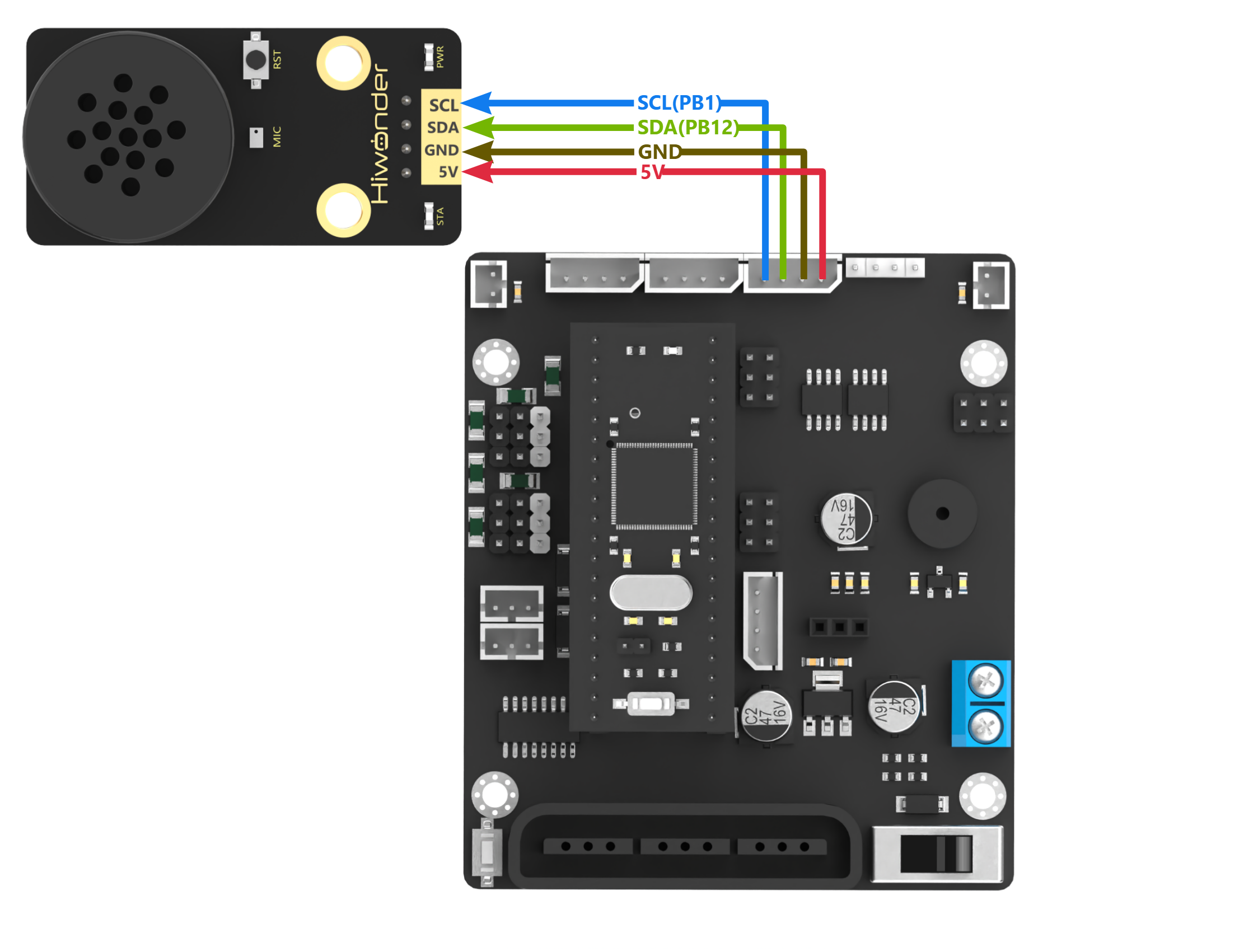
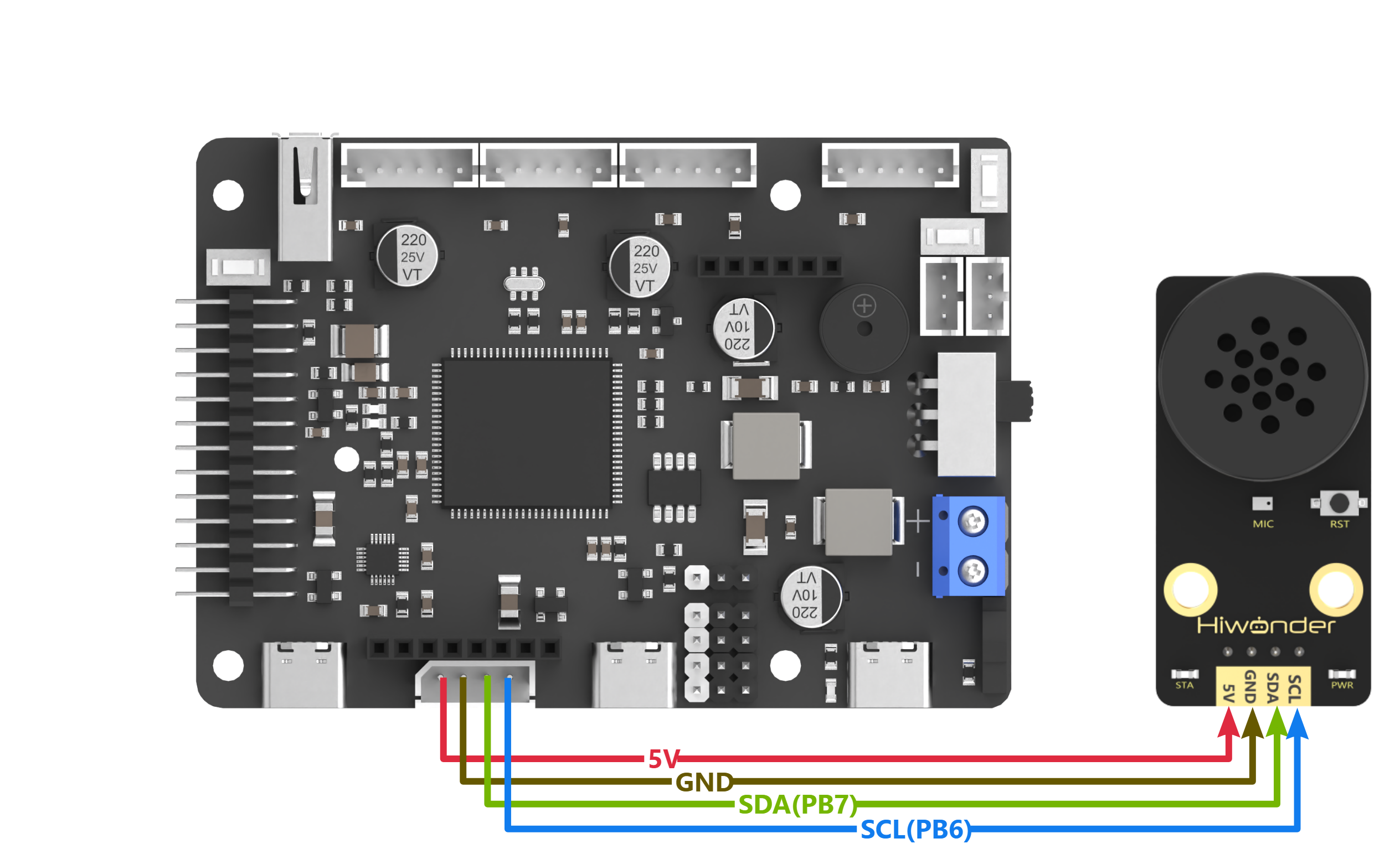
(1) Wiring Instruction
Connect the 5V, GND, SDA, and SCL pins of the voice recognition module to the corresponding pins on the Arduino.
{Note} Before powering on, ensure that no metal objects come into contact with the controller. This action prevents a short circuit caused by the bottom pins of the controller, which may damage the controller.
(2) Arduino Program Download
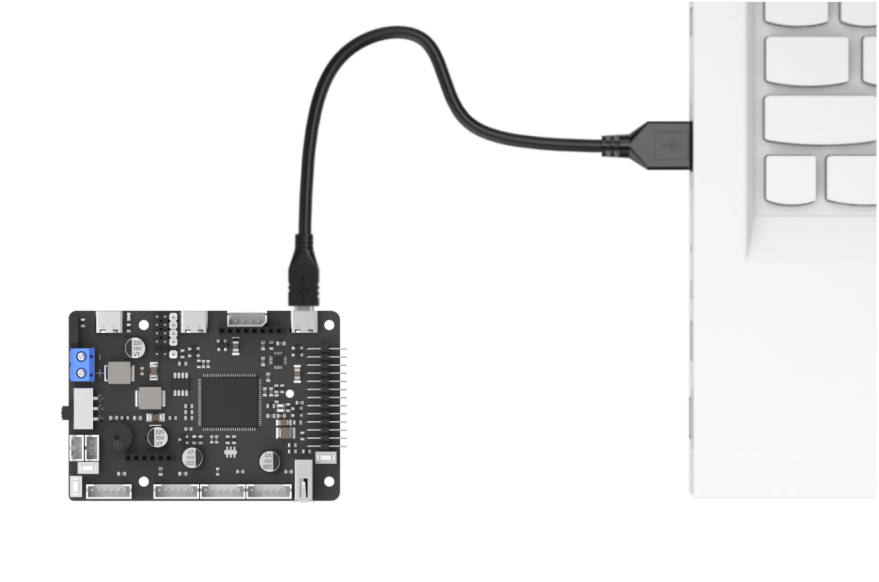
① Connect Arduino controller to the computer with a data cable.
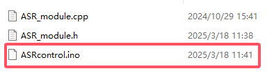
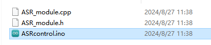
② Locate and open “ASRcontrol\ASRcontrol.ino” program file .
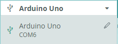
(3) Click “Select Board,” and the software will automatically detect the current Arduino serial port. Next, click to connect.

(4) Click  to download the program into Arduino. Then just wait for it to complete.


Test Case
This program allows the voice recognition module to recognize predefined commands.
(1) Program Outcome
{Note} To start voice recognition, wake up the module by saying “Hello Hiwonder.” It’ll only respond to commands after it’s been activated.
① When the command “go straight” is recognized, the voice recognition module will broadcast “going straight,” and the serial port will print “go.”
② When the command “go backward” is recognized, the voice recognition module will broadcast “going backward,” and the serial port will print “back.”
③ When the command “turn left” is recognized, the voice recognition module will broadcast “turning left,” and the serial port will print “left.”
④ When the command “turn right” is recognized, the voice recognition module will broadcast “turning right,” and the serial port will print “right.”
⑤ When the command “stop” is recognized, the voice recognition module will broadcast “copy that,” and the serial port will print “stop.”

(2) Brief Program Analysis
① Import the necessary libraries for Wire and ASR_module to enable communication with the voice recognition module.
10 11 | #include <Wire.h> #include "ASR_module.h" |
② Create an object for the voice recognition module. Initialize the variable “result” to receive data from the module. Set the serial baud rate to 115200.
18 19 20 21 22 23 24 25 26 | ASR_MOUDLE asr; uint8_t result = 0; void setup() { Serial.begin(115200); Serial.println("Start"); } |
③ In the main function, call the asr.rec_recognition() function to retrieve data from the voice recognition module.
28 29 30 | void loop() { result = asr.rec_recognition(); //Return Recognition Result: The recognized entry ID. |
④ When the command “go straight” is recognized, the module will return 0x01. When “go backward” is recognized, it will return 0x02, and so on for other command words. Each command corresponds to a specific hexadecimal value. For a detailed list of the data, please refer to the Command Word & Broadcast Statement Protocol List.
31 32 33 34 35 36 37 38 39 40 41 42 43 44 45 46 47 48 49 50 51 | if(result != 0) { if(result == 0x01) { Serial.println("go"); }else if(result == 0x02) { Serial.println("back"); }else if(result == 0x03) { Serial.println("left"); }else if(result == 0x04) { Serial.println("right"); }else if(result == 0x09) { Serial.println("stop"); } } delay(50); } |
4.3.2 Arduino Voice Broadcast
Getting Ready
(1) Wiring Instruction
Connect the 5V, GND, SDA, and SCL pins of the voice recognition module to the corresponding pins on the Arduino.

{Note} Before powering on, ensure that no metal objects come into contact with the controller. This action prevents a short circuit caused by the bottom pins of the controller, which may damage the controller.
(2) Arduino Program Download
① Connect Arduino controller to the computer with a data cable.
② Locate and open “ASRcontrol\ASRcontrol.ino” program file in the same directory of this section.
③ Click “Select Board,” and the software will automatically detect the current Arduino serial port. Next, click to connect.
④ Click  to download the program into Arduino. Then just wait for it to complete.


Test Case
This program enables the voice recognition module to broadcast the prewritten statements.
(1) Program Outcome
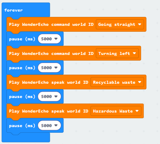
The voice recognition module is controlled to sequentially broadcast “Going straight,” “Turning left,” “Recyclable waste,” and “Hazardous waste” in a loop, with a 5-second interval for each broadcast.
(2) Brief Program Analysis
① Import the necessary libraries for Wire and ASR_module to enable communication with the voice recognition module.
10 11 | #include <Wire.h> #include "ASR_module.h" |
② Create an object for the voice recognition module. Initialize the “result” variable to receive data from the module. Set the serial baud rate to 115200.
18 19 20 21 22 23 24 25 26 | ASR_MOUDLE asr; uint8_t result = 0; void setup() { Serial.begin(115200); Serial.println("Start"); } |
③ In the main function, call the asr.speak() function to send data to the voice recognition module. This function takes two parameters:
61 62 63 64 65 66 67 68 69 | void ASR_MOUDLE::speak(uint8_t cmd , uint8_t id) { if(cmd == 0xFF || cmd == 0x00) { send[0] = cmd; send[1] = id; WireWriteDataArray(ASR_SPEAK_ADDR , send , 2); } } |
④ The ASR_COMMAND register address in the voice recognition module signifies a command word. When its value is 0x00, it indicates the function type being written is a command word. For example, writing 0x01 to the ASR_COMMAND register corresponds to the broadcast statement “Going straight” from the data list, while 0x03 corresponds to “Turning left.”
28 29 30 31 32 33 | void loop() { asr.speak(ASR_CMDMAND , 0x01); // Command word broadcast: "Going forward" delay(5000); asr.speak(ASR_CMDMAND , 0x03); // Command word broadcast: "Turning left" delay(5000); |
⑤ If the value of ASR_ANNOUNCER is set to 0xFF, it indicates the function type being written is a broadcast statement. For instance, writing 0x01 to the ANNOUNCER register corresponds to the broadcast statement “Recyclable waste” from the data list, while 0x03 corresponds to “Hazardous waste.”
35 36 37 38 39 | asr.speak(ASR_ANNOUNCER , 0x01); // Broadcast: "Recyclable Waste" delay(5000); asr.speak(ASR_ANNOUNCER , 0x03); // Broadcast: "Hazardous Waste" delay(5000); } |
⑥ For a detailed list of data, please refer to the Command Word Broadcasting Protocol List.
4.4 STM32 Communication
4.4.1 STM32F103 Voice Recognition
Getting Ready
(1) Wiring Instruction
Connect the voice recognition module to the corresponding port on the STM32 board with a 4Pin wire.

{Note} Before powering on, ensure that no metal objects come into contact with the controller. This action prevents a short circuit caused by the bottom pins of the controller, which may damage the controller.
(2) Program Download
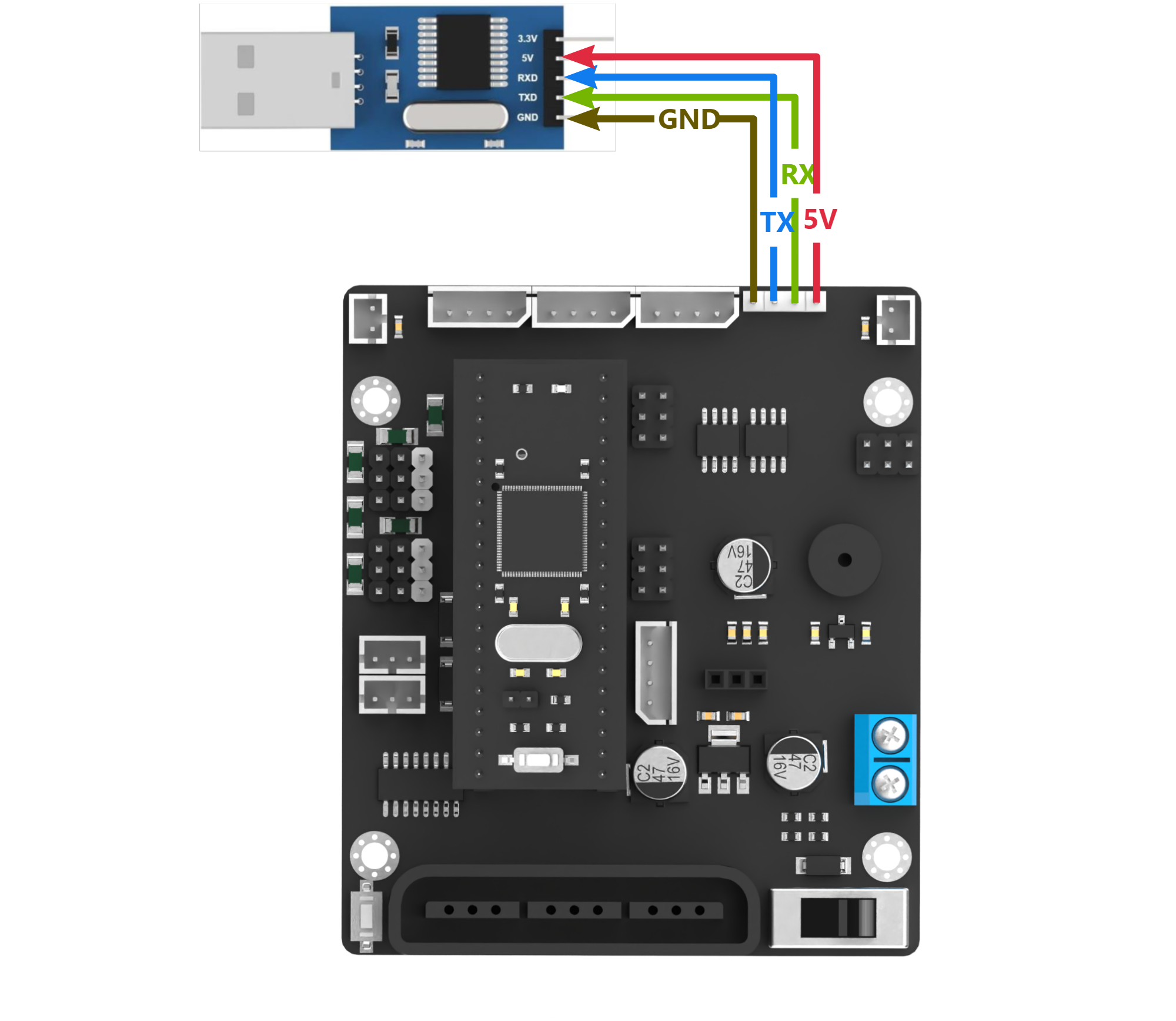
Prepare an STM32F103 controller, an open-source robot controller, DuPont wires, and a USB to TTL converter.
① Connect the STM32 board to the PC via the USB to TTL tool.
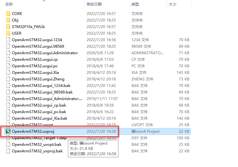
② Open the STM32 program file in the “STM32F103_Asr_recognition”.

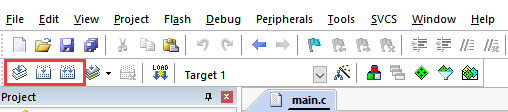
③ Generate all the code to the executable file.

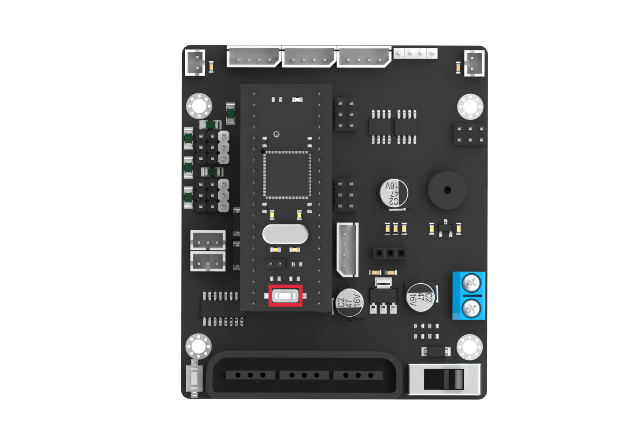
④ Remove the jumper cap on the development board. Press the RST button.
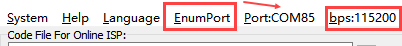
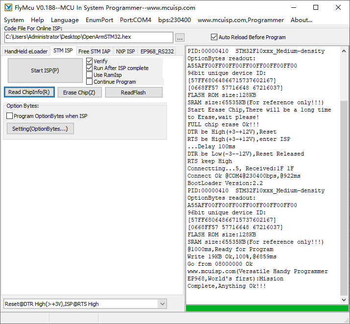
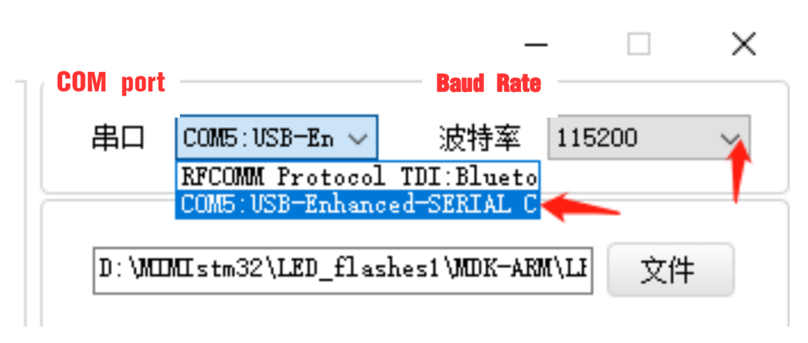
⑤ Open the mcuisp software  . Select the corresponding serial port, and set the baud rate to
 115200. Download the program to the development board.
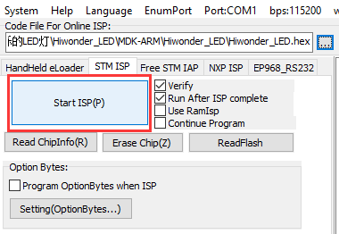
⑥ Click  to open the hex file “STM32F103_Asr_recognition\Obj\OpenArmSTM32”.

⑦ Click “Start ISP” to flash the generated hex file into the STM32 control board.
⑧ After the download is completed, reconnect the jumper cap to the STM32. Press the RST button to run the program.
Test Case
This program enables the voice recognition module to recognize the prewritten commands.
(1) Program Outcome
① When the command “go straight” is recognized, the voice recognition module will broadcast “going straight,” and the serial port will print “go.”
② When the command “go backward” is recognized, the voice recognition module will broadcast “going backward,” and the serial port will print “back.”
③ When the command “turn left” is recognized, the voice recognition module will broadcast “turning left,” and the serial port will print “left.”
④ When the command “turn right” is recognized, the voice recognition module will broadcast “turning right,” and the serial port will print “right.”
⑤ When the command “stop” is recognized, the voice recognition module will broadcast “copy that,” and the serial port will print “stop.”
(2) Brief Program Analysis
① Import the necessary libraries for I2C communication with the voice recognition module.
1 2 3 | #include "include.h" #include "IIC.h" #include <string.h> |
② Initialize the serial port and I2C communication. Set the baud rate to 9600.
16 17 18 19 20 21 | SystemInit(); InitDelay(72); //Initialize delay functions Usart1_Init(); //Initialize UART1 IIC_Init(); //Initialize I2C DelayMs(200); printf("start"); |
③ In the main function, create a result variable to store the recognition result. Use the Asr_Result() function to obtain the recognition result.
24 25 | u8 result; result = Asr_Result(); //Return the recognition result, i.e., the ID of the recognized phrase |
④ When the command “go straight” is recognized, the module will return 0x01. When “go backward” is recognized, it will return 0x02, and so on for other command words. Each command corresponds to a specific hexadecimal value. For a detailed list of the data, please refer to the Command Word Broadcasting Protocol List.
26 27 28 29 30 31 32 33 34 35 36 37 38 39 40 41 42 43 44 45 46 47 | if(result != 0) { if(result == 0x01) { printf("go"); }else if(result == 0x02) { printf("back"); }else if(result == 0x03) { printf("left"); }else if(result == 0x04) { printf("right"); }else if(result == 0x09) { printf("stop"); } } DelayMs(50); } } |
4.4.2 STM32F407 Voice Recognition
Getting Ready
(1) Wiring Instruction
Connect the voice recognition module to the corresponding port on the STM32F407 board with a 4Pin wire.
{Note} Before powering on, ensure that no metal objects come into contact with the controller. This action prevents a short circuit caused by the bottom pins of the controller, which may damage the controller.
(2) Program Download
① Connect the UART1 port on the STM32 controller to the PC using a Type-C cable.

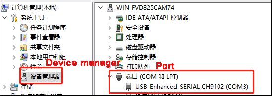
② Open the Device Manager to check the serial port number.

③ Launch the ATX-XISP software, select the corresponding serial port, and set the baud rate to 115200.
④ Follow the instructions below to configure the settings.
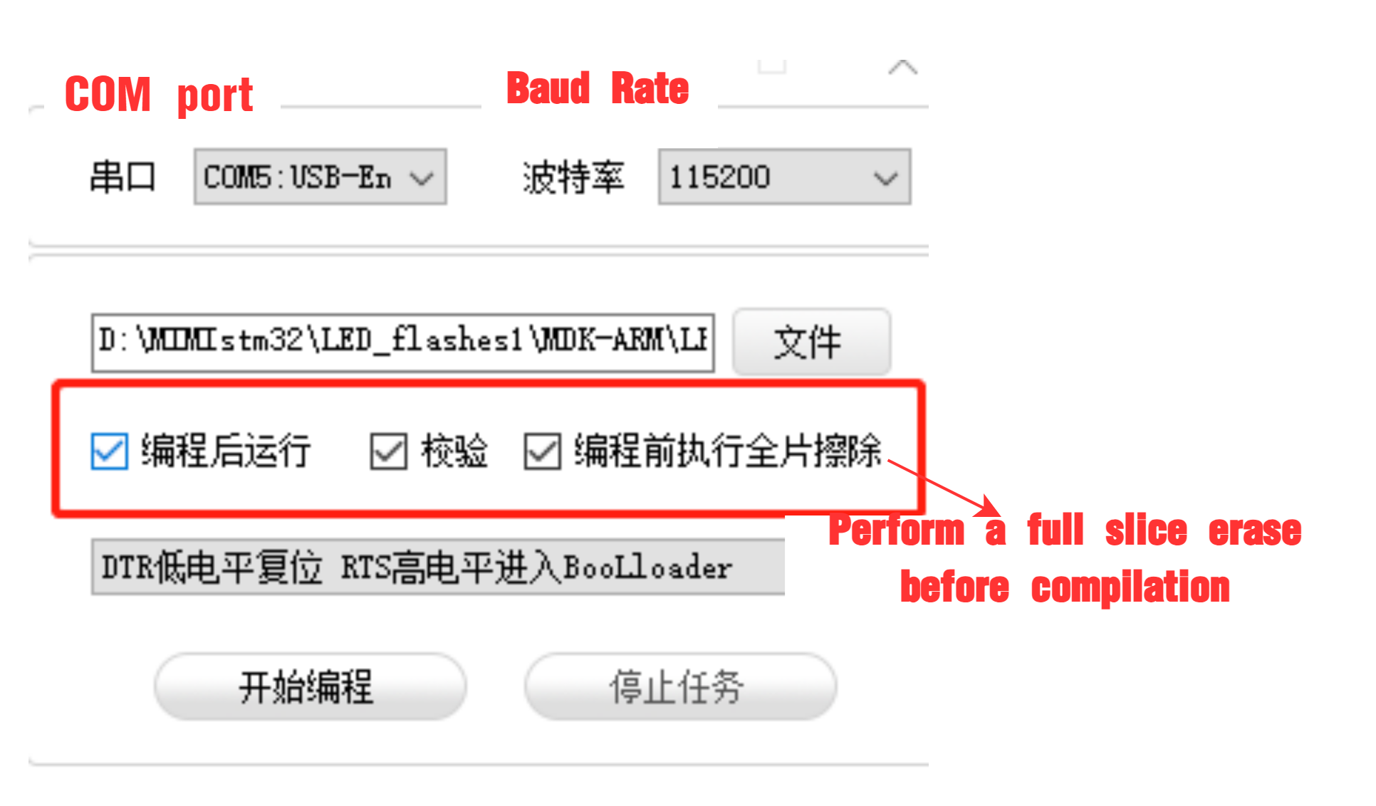
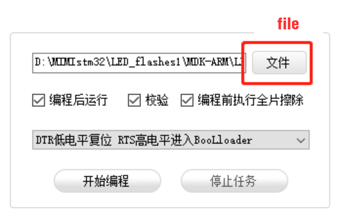
⑤ Click “File” and select the program file: STM32F407_ASR_recognition\MDK-ARM\RosRobotControllerM4\RosRobotControllerM4.hex for downloading.
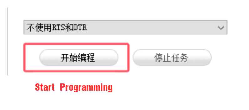
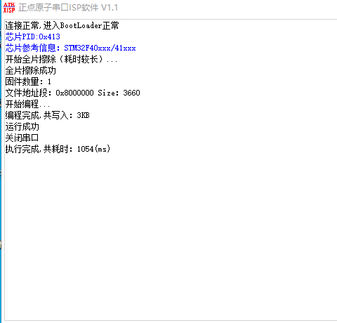
⑥ Click “Start Programming” to flash the generated hex file onto the STM32 control board.


Test Case
This program uses the STM32F407 development board to obtain the module’s recognition result, printing the result via the UART1.
(1) Program Outcome
① When the command “go straight” is recognized, the voice recognition module will broadcast “going straight,” and the serial port will print “go.”
②When the command “go backward” is recognized, the voice recognition module will broadcast “going backward,” and the serial port will print “back.”
③ When the command “turn left” is recognized, the voice recognition module will broadcast “turning left,” and the serial port will print “left.”
④ When the command “turn right” is recognized, the voice recognition module will broadcast “turning right,” and the serial port will print “right.”
⑤ When the command “stop” is recognized, the voice recognition module will broadcast “copy that,” and the serial port will print “stop.”
(2) Brief Program Analysis
① Import the necessary libraries for I2C communication with the voice recognition module.
12 13 | #include "cmsis_os2.h" #include "global.h" |
② Define the I2C address of the voice recognition module, as well as the register, command word, and broadcast statement.
15 16 17 18 19 20 21 22 23 | #define ASR_ADDR 0x34 //Storage location for recognition results; continuously reading this address determines whether a voice command has been recognized, with different values corresponding to different commands. //识别结果存放处,通过不断读取此地址的值判断是否识别到语音,不同的值对应不同的语音 #define ASR_RESULT_ADDR 100 #define ASR_SPEAK_ADDR 110 #define ASR_CMDMAND 0x00 #define ASR_ANNOUNCER 0xFF |
③ In the main function, create a result variable to store the recognition result. Use the HAL_I2C_Mem_Read() function to obtain the recognition result.
35 36 | uint8_t result = 0; HAL_I2C_Mem_Read(&hi2c2, ASR_ADDR << 1, ASR_RESULT_ADDR, I2C_MEMADD_SIZE_8BIT, &result, 1, 0xFF); |
④ When the command word “go straight” is recognized, the module will return 0x01. If “go backward” is recognized, it will return 0x02. This pattern continues for other command words, with each corresponding to a specific hexadecimal value. For a detailed list of these values, please refer to the Command Word Broadcasting Protocol List.
37 38 39 40 41 42 43 44 45 46 47 48 49 50 51 52 53 54 55 56 57 58 | if(result != 0) { if(result == 0x01) { printf("go"); }else if(result == 0x02) { printf("back"); }else if(result == 0x03) { printf("left"); }else if(result == 0x04) { printf("right"); }else if(result == 0x09) { printf("stop"); } } osDelay(100); //Delay(延时) } } |
4.4.3 STM32F103 Voice Broadcast
Getting Ready
(1) Wiring Instruction
Connect the voice recognition module to the corresponding port on the STM32 board with a 4Pin wire.
{Note} Before powering on, ensure that no metal objects come into contact with the controller. This action prevents a short circuit caused by the bottom pins of the controller, which may damage the controller.
(2) Program Download
Prepare an STM32F103 development board, an open-source robot controller, DuPont wires, and a USB to TTL converter.
① Connect the STM32 board to the PC via the USB to TTL tool.
② Open the STM32 program file in the “STM32F103_Asr_announce”.
③ Generate all the code to the executable file.
④ Remove the jumper cap on the development board. Press the RST button.
⑤ Open the mcuisp software  . Select the corresponding serial port, and set the baud rate to
 115200. Download the program to the development board.

⑥ Click  to open the hex file “STM32F103_Asr_announce\Obj\OpenArmSTM32”.

⑦ Click “Start ISP” to flash the generated hex file into the STM32 control board.


⑧ After the download is completed, reconnect the jumper cap to the STM32. Press the RST button to run the program.
Test Case
This program enables the voice recognition module to broadcast the prewritten statements.
The voice recognition module is controlled to sequentially broadcast “Going straight,” “Turning left,” “Recyclable waste,” and “Hazardous waste” in a loop, with a 5-second interval for each broadcast.
Brief Program Analysis
(1) Import the necessary libraries for I2C communication with the voice recognition module.
1 2 3 | #include "include.h" #include "IIC.h" #include <string.h> |
(2) Initialize the serial port and I2C communication, and set the baud rate to 9600.
16 17 18 19 20 21 | SystemInit(); InitDelay(72); //Initialize the delay function Usart1_Init(); //Initialize the serial port IIC_Init(); //IIC initialization DelayMs(200); printf("start"); |
(3) In the main function, use the asr.speak() function to write data to the voice recognition module. This function requires two parameters:
Parameter 1: The register address, indicating whether the data is a command word or a broadcast statement.
Parameter 2: The corresponding value of the broadcast statement.
155 156 157 158 159 160 161 162 163 164 165 166 167 168 169 170 171 172 173 174 175 176 177 178 | void Asr_Speak(u8 cmd ,u8 idNum) { int i; int addr = Asr_Addr; u8 send[2] = {0x00 , 0x00}; if(cmd == 0xFF || cmd == 0x00) { send[0] = cmd; send[1] = idNum; IIC_Start(); IIC_Send_Byte(addr<<1 | 0); IIC_Wait_Ack(); IIC_Send_Byte(ASR_SPEAK_ADDR); IIC_Wait_Ack(); //IIC_Stop(); for(i = 0; i < 2; ++i) { IIC_Send_Byte(send[i]); IIC_Wait_Ack(); } IIC_Stop(); DelayMs(20); } } |
(4) The ASR_COMMAND register address represents the command word section of the voice recognition module. When its value is 0x00, it indicates that the function type is a command word.
For example, writing
0x01to theASR_COMMANDregister corresponds to the broadcast statement “Going straight” from the data list.Similarly, writing
0x03corresponds to the broadcast statement “Turning left”.
24 25 26 27 | Asr_Speak(ASR_CMDMAND , 0x01); // Command phrase playback: "Moving forward" DelayMs(5000); Asr_Speak(ASR_CMDMAND , 0x03); // Command phrase playback: "Turning left" DelayMs(5000); |
(5) If the value of ASR_ANNOUNCER is set to 0xFF, it specifies that the function type is a broadcast statement.
Writing
0x01to theASR_ANNOUNCERregister corresponds to the broadcast statement “Recyclable waste”.Similarly, writing
0x03corresponds to the broadcast statement “Hazardous waste”.
28 29 30 31 32 33 | Asr_Speak(ASR_ANNOUNCER , 0x01); // Announcement phrase playback: "Recyclable waste" DelayMs(5000); Asr_Speak(ASR_ANNOUNCER , 0x03); // Announcement phrase playback: "Hazardous waste" DelayMs(5000); } } |
(6) For a detailed list of the data values, please refer to the Command Word Broadcasting Protocol List.
4.4.4 STM32F407 Voice Broadcast
Getting Ready
(1) Wiring Instruction
Connect the voice recognition module to the corresponding port on the STM32F407 board with a 4Pin wire.
{Note} Before powering on, ensure that no metal objects come into contact with the controller. This action prevents a short circuit caused by the bottom pins of the controller, which may damage the controller.
(2) Program Download
① Connect the UART1 port on the STM32 controller to the PC with a Type-C cable.
② Open the device manager to check the serial port number.
③ Open the ATX-XISP software to select the corresponding serial port. Set the baud rate to 115200.

④ Follow the instructions below to configure it.

⑤ Decompress the STM32F407_ASR_announce.zip file in the same directory as this lesson. Click “File” in the software to select the program file STM32F407_ASR_announcement\MDK-ARM\RosRobotControllerM4\RosRobotControllerM4.hex for downloading.

(6) Click “Start programming” to flash the generated hex file into the STM32 control board.
Test Case
This program enables the voice recognition module to broadcast the prewritten statements.
The voice recognition module is controlled to sequentially broadcast “Going straight,” “Turning left,” “Recyclable waste,” and “Hazardous waste” in a loop, with a 5-second interval for each broadcast.
Brief Program Analysis
(1) Import function libraries related to controller communication for the voice recognition module.
12 13 | #include "cmsis_os2.h" #include "global.h" |
(2) Define the I2C address of the voice recognition module. Define the register, command word, and broadcast statement.
17 18 19 20 21 22 23 | // Recognition result storage; continuously reading this address determines if a voice command is recognized, with different values representing different commands. // 识别结果存放处,通过不断读取此地址的值判断是否识别到语音,不同的值对应不同的语音 #define ASR_RESULT_ADDR 100 #define ASR_SPEAK_ADDR 110 #define ASR_CMDMAND 0x00 #define ASR_ANNOUNCER 0xFF |
(3) In the main function, call the HAL_I2C_Mem_Write() function to write data to the voice recognition module. The function contains two parameters. Within the speak_cmd array, the parameter 1 is the register address of the command word. Parameter 2 represents the value of the corresponding broadcast statement. The ASR_COMMAND signifies the register address of the command word within the voice recognition module. When its value is 0x00, it means that the function type to be written is a command word. Start by writing 0x01 to the register address ASR_COMMAND, which corresponds to the broadcast statement “Going straight” in the data list. Similarly, the value 0x03 corresponds to the “Turning left”.
33 34 35 36 37 38 39 40 41 42 | // Loop: In RTOS tasks, the loop must include osDelay or another system blocking function, otherwise it may cause system instability. // 循环 : RTOS任务中的循环,必须要有osDelay或者其他系统阻塞函数,否则会导致系统异常 for(;;) { uint8_t speak_cmd[2] = {ASR_CMDMAND , 0x01}; HAL_I2C_Mem_Write(&hi2c2, ASR_ADDR << 1, ASR_SPEAK_ADDR, I2C_MEMADD_SIZE_8BIT, speak_cmd, 2, 0xFF); // Command phrase playback: "Moving forward"(命令词播报语 播报:正在前进) osDelay(5000); speak_cmd[1] = 0x03; HAL_I2C_Mem_Write(&hi2c2, ASR_ADDR << 1, ASR_SPEAK_ADDR, I2C_MEMADD_SIZE_8BIT, speak_cmd, 2, 0xFF); // Command phrase playback: "Turning left"(命令词播报语 播报:正在左转) osDelay(5000); |
(4) Within the speak_ann array, the parameter 1 is the register address of the broadcast statement. Parameter 2 represents the value of the corresponding broadcast statement. If the value of ASR_ANNOUNCER is set to 0xFF, it indicates that the function type to be written is broadcast statement. Write 0x01 to the register address ANNOUNCER, which corresponds to the broadcast statement “Recyclable waste” in the data list. Similarly, the data 0x03 corresponds to “Hazardous waste”.
44 45 46 47 48 49 50 51 52 | uint8_t speak_ann[2] = {ASR_ANNOUNCER , 0x01}; HAL_I2C_Mem_Write(&hi2c2, ASR_ADDR << 1, ASR_SPEAK_ADDR, I2C_MEMADD_SIZE_8BIT, speak_ann, 2, 0xFF); // Announcement playback: "Recyclable waste"(播报语 播报:可回收物) osDelay(5000); speak_ann[1] = 0x03; HAL_I2C_Mem_Write(&hi2c2, ASR_ADDR << 1, ASR_SPEAK_ADDR, I2C_MEMADD_SIZE_8BIT, speak_ann, 2, 0xFF); // Announcement playback: "Hazardous waste"(播报语 播报:有害垃圾) osDelay(5000); } } |
(5) For the detailed data list, please refer to the Command Word&Broadcast Statement Protocol List.
4.5 Raspberry Pi Communication
4.5.1 Remote Connectivity and File Transfer
Preparation
(1) Hardware Preparation
Prepare a laptop for the setup. If you’re using a desktop computer, make sure to have a wireless network adapter, as it is necessary to connect both the desktop and the Raspberry Pi 5 to the same local network.
(2) MobaXterm Tool Installation and Usage
MobaXterm is a software that integrates various remote computing tools and provides a graphical interface. By connecting to the Raspberry Pi’s Wi-Fi hotspot, you can control the Raspberry Pi directly from your computer. Follow the steps below to install the software:
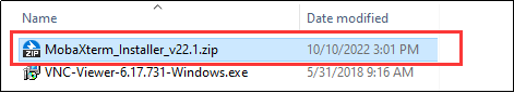
① Extract the MobaXterm_Installer_v22.1.zip file.
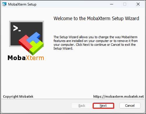
② Double-click the “MobaXterm_installer_22.1.msi” file in the extracted “MobaXterm_Installer_v22.1” folder and click “Next.”
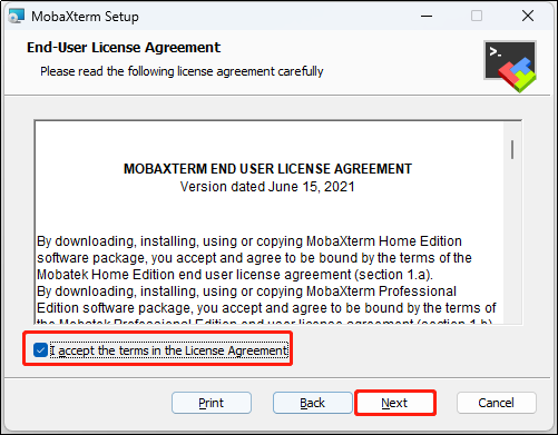
③ In the pop-up window, accept the license agreement and click “Next.”
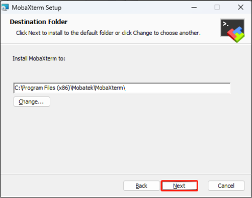
④ Choose the installation path and click “Next.”
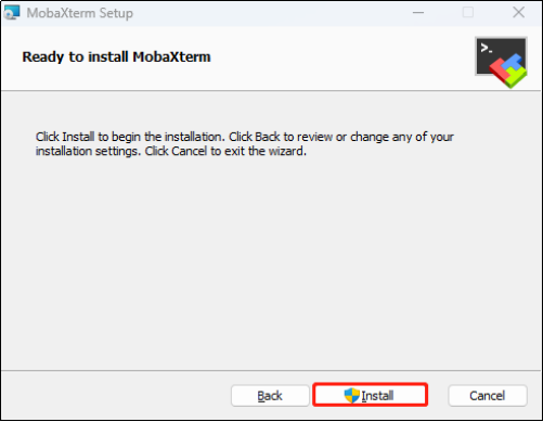
⑤ Click “Install.”
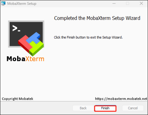
⑥ Wait for the installation to complete. Once finished, a prompt will appear indicating the installation is complete. Click the “Finish” button to complete the process.
(3) Start Raspberry Pi 5
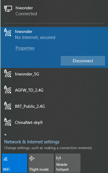
① Connect the Raspberry Pi 5 to the local network. In this tutorial, the Raspberry Pi 5 is already connected to the “Hiwonder” hotspot. Next, connect your computer to the same “Hiwonder” hotspot.
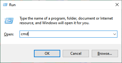
② Press Win + R to open the “Run” dialog, type “cmd” and press Enter to open the Command Prompt in administrator mode.
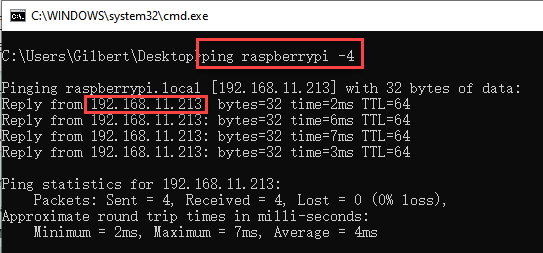
③ Type the command “ping raspberrypi -4” and press Enter to find the IP address assigned to the Raspberry Pi 5 by the hotspot.
Connect to Raspberry Pi 5 using MobaXterm
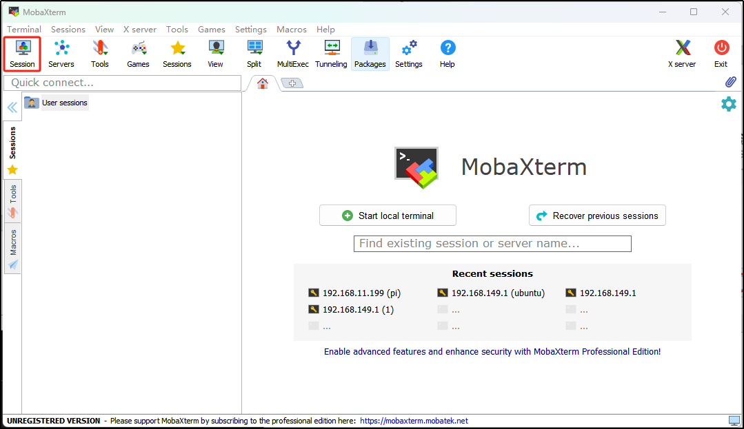
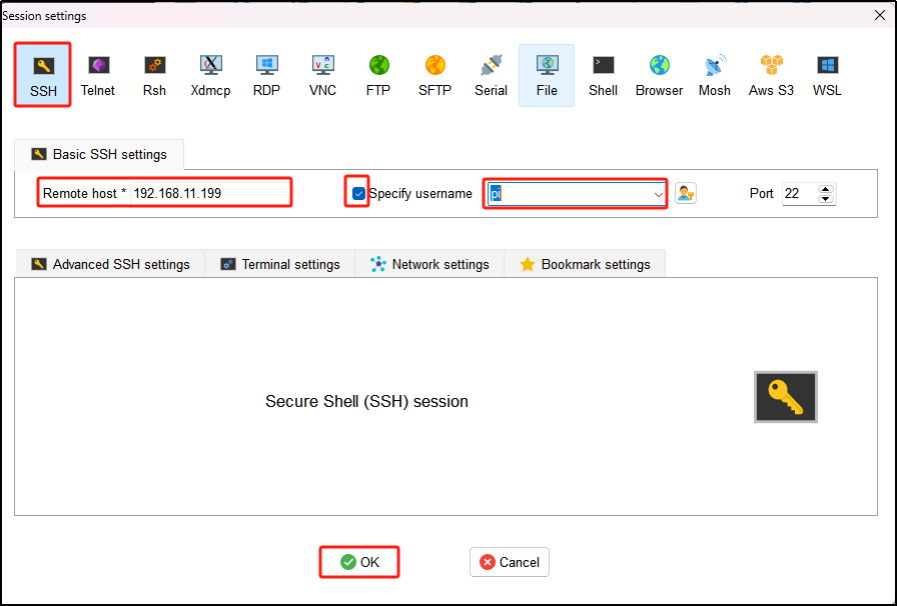
(1) Open MobaXterm. In the main interface, click on the “Session” button in the top-left corner to create a new session.
(2) In the session window, select “SSH.” Enter the Raspberry Pi’s IP address (“192.168.11.199”), check the “Specify username” box, and input the username “pi.” Then, click “OK.”
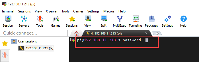
(3) On the first connection, you will be prompted to enter the Raspberry Pi 5’s password, which is “raspberrypi.” The password will not be visible as you type. After entering it correctly, press Enter.
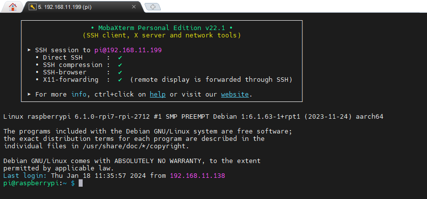
(4) Once the password is verified, you will successfully log into the system. The system interface will appear as shown in the image below:
File Transfer Between Raspberry Pi and Computer
Transferring files between your computer and Raspberry Pi is a common task. In this section, we’ll demonstrate how to do this using SSH and MobaXterm. For other file transfer methods, you can search online for further guidance.
(1) Transfer Files from Computer to Raspberry Pi
① After establishing the SSH connection, create a “test.txt” file on your computer’s desktop as an example.
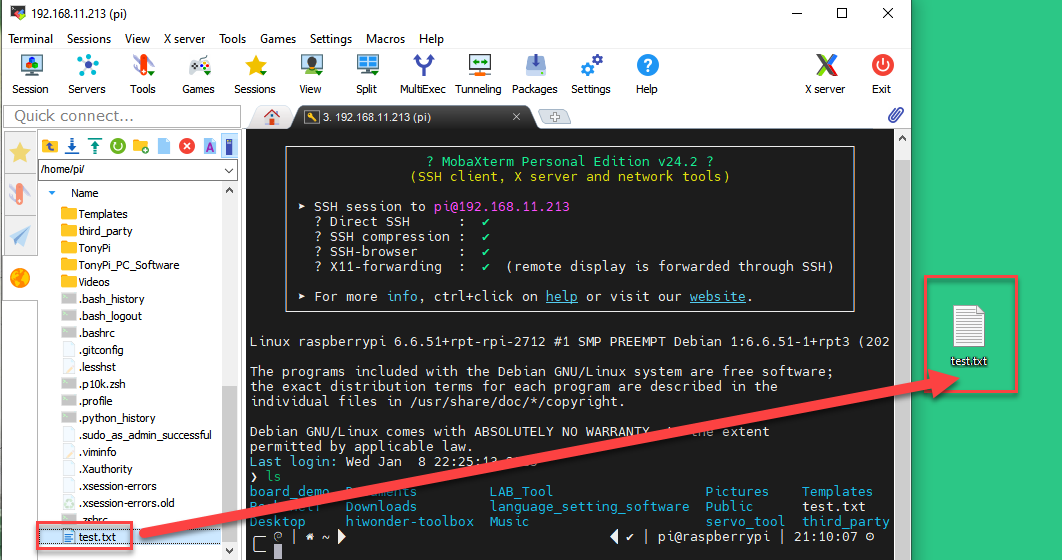
② Adjust the zoom level in MobaXterm and select the file you wish to transfer. Drag and drop the file into the MobaXterm file area.
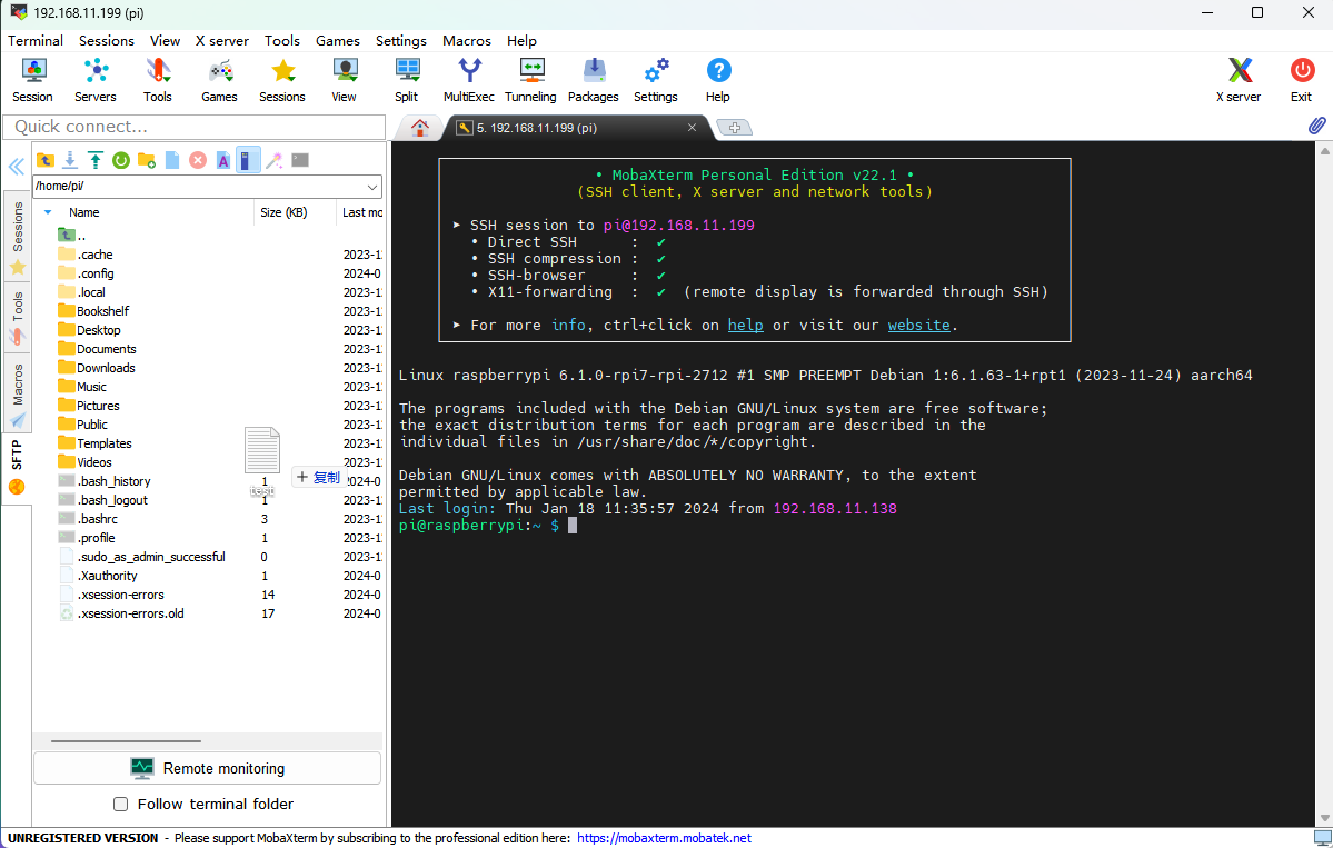
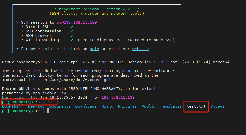
③ The file will automatically be transferred to the Raspberry Pi desktop. To view all files, type the “ls” command and press Enter. As shown in the image below, the file has been successfully transferred from the computer.
(2) Transfer Files from Raspberry Pi to Computer
After establishing the SSH connection, navigate to the file you want to transfer in the MobaXterm file area. Drag and drop the file onto your computer’s desktop, and it will be automatically transferred.
Enable VNC Connection
If you’re not comfortable with the command line or prefer an alternative, the official Raspberry Pi 5 system image doesn’t enable VNC by default. You can enable it through an SSH connection.
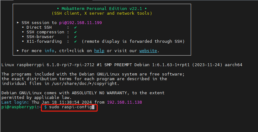
(1) After connecting via SSH, type sudo raspi-config and press Enter to open the Raspberry Pi configuration menu.
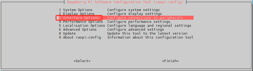
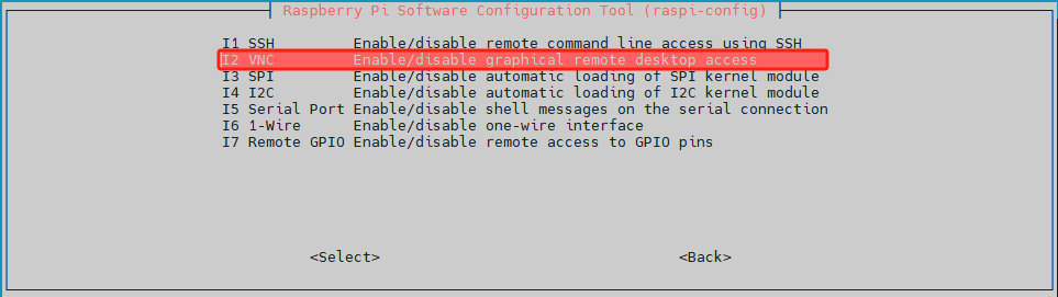
(2) Use the “↑” and “↓” arrow keys to navigate, “Enter” to confirm a selection, and “Esc” to go back. Select “Interface Options” and press Enter to proceed to the related settings.
(3) Locate “I2 VNC” and press Enter to access the VNC switch screen.
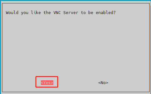
(4) Select “Yes” and press Enter to enable the VNC connection.
After enabling VNC, you can connect to the Raspberry Pi 5 system via VNC.
VNC Installation and Connection
VNC is a remote desktop software that enables you to control your system remotely through a graphical interface, similar to the Windows desktop.
(1) Installing VNC
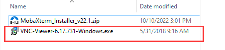
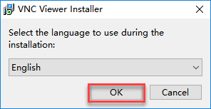
① Double-click the VNC-Viewer-6.17.731-Windows file . In the pop-up dialog, select “English” as the installation language and click “OK.”
② Click the “Next” button in the following window.
③ In the next prompt, agree to the license agreement and click “Next.” When the installation location settings appear, keep the default and click “Next” again.
④ Click the “Install” button in the next window.

⑤ Wait for the installation to finish. Once complete, a confirmation message will appear. Click “Finish” to complete the installation.
⑥ After installation, click the VNC icon  to open the software and start the connection.
(2) VNC Connection
① Connect the Raspberry Pi 5 to the local network. For this tutorial, the Raspberry Pi 5 is already connected to the “Hiwonder” hotspot. Now, connect your computer to the same “Hiwonder” hotspot.

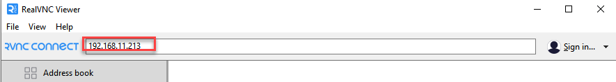
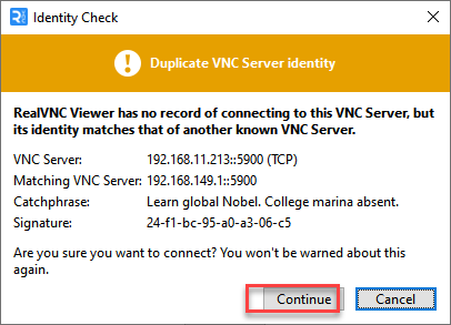
② Launch the installed VNC client. In the VNC Viewer that opens, enter the Raspberry Pi 5’s IP address: 192.168.11.199, then press Enter. If a warning about an insecure connection appears, click “Continue.”
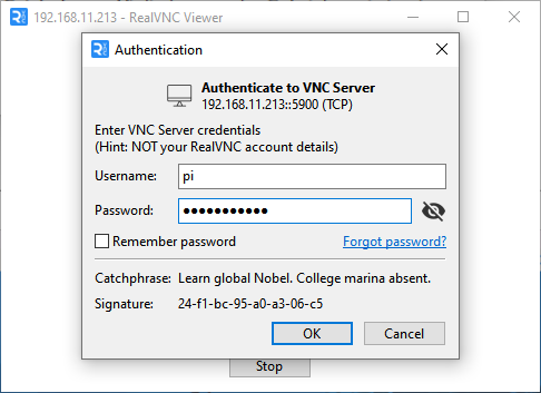
③ A prompt will appear asking for the password. Enter the password: “raspberrypi” (if prompted for a username, enter “pi”). Check the box to save the password, then click “OK.” You will now be able to view the Raspberry Pi desktop remotely.
(If the screen is black with only the mouse pointer visible, try restarting the Raspberry Pi and repeating the steps.)

4.5.2 Raspberry Pi Voice Recognition
Preparation
(1) Wiring Setup
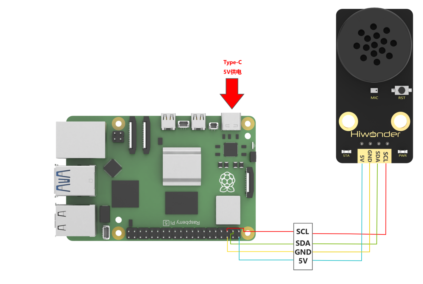
When wiring, the 5V, GND, SDA, and SCL pins of the voice interaction module need to be connected to the Raspberry Pi. The wiring method is shown in the image below:
Note
Before powering on, make sure no metal objects come into contact with the motherboard, as this could cause a short circuit from the pins on the underside, potentially damaging the board.
The I2C pin configuration on the Raspberry Pi 4 is identical to that on the Raspberry Pi 5, so this wiring method is also compatible with the Raspberry Pi 4.
(2) Importing and Running the Program
Note
For instructions on installing and using MobaXterm and VNC Viewer, refer to 4.5.1 Remote Connectivity and File Transfer.
① Use MobaXterm to transfer the speech_recognition.py file (located in the same directory as this document) to the Raspberry Pi. In this example, we drag the file to the desktop. Then, connect to the Raspberry Pi using VNC Viewer.

② On the Raspberry Pi, press Ctrl + Alt + T to open the terminal.
③ Navigate to the directory where the program is stored by entering:
cd Desktop/
④ Run the program with the following command:
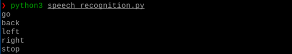
python3 speech_recognition.py
Test Case
This example demonstrates how the Raspberry Pi retrieves recognition results from the voice interaction module and displays them in the command-line terminal.
(1) Expected Behavior
Note
Before issuing commands, you must wake up the module by saying “Hello Hiwonder”
① When the voice interaction module detects “Move forward”, it responds with “Moving forward”, and the terminal outputs: go
② When it detects “Move backward”, it responds with “Moving backward”, and the terminal outputs: back
③ When it detects “Turn left”, it responds with “Turning left”, and the terminal outputs: left
④ When it detects “Turn right”, it responds with “Turning right”, and the terminal outputs: right
⑤ When it detects “Stop” or “Halt”, it responds with “Received”, and the terminal outputs: stop
The terminal output should look similar to this:
(2) Brief Program Analysis
① Library Imports: The program imports the smbus library for I2C bus communication and the time library for time processing. These libraries facilitate communication with the voice interaction module.
94 95 96 97 | #!/usr/bin/python3 # coding=utf8 import smbus import time |
② Object Creation: An object named asr_module is instantiated from the ASRModule class to represent the voice interaction module. Another variable, recognition_result, stores the recognition output. During initialization, the I2C address of the integrated voice interaction module is provided to establish a communication link with the Raspberry Pi bus.
26 27 | if __name__ == "__main__": asr_module = ASRModule(I2C_ADDR) |
③ Class Initialization: When the ASRModule class is instantiated, it automatically creates a member object bus by instantiating the SMBus class from the smbus library. This enables communication with the Raspberry Pi’s I2C bus. The provided I2C slave address is specified for communication during initialization.
33 34 35 36 37 38 | class ASRModule: def __init__(self,address, bus=1): # Initialize the I2C bus and device address self.bus = smbus.SMBus(bus) # Use I2C bus 1 self.address = address # I2C address of the device self.send = [0, 0] # Initialize the list for sending data |
④ Reading Recognition Results: This section focuses on reading recognition result data stored in the module’s registers. To achieve this, a function named wire_read_data_array is defined within the ASRModule class to read data from the slave device via the I2C bus.
The function accepts two parameters: the register address reg and the length of data length to be read.
It leverages the read_i2c_block_data() function from the bus (an SMBus object) to read data from the specified register.
The third parameter of read_i2c_block_data() specifies the number of bytes to read, returning a list with a length equal to the number of bytes read. This list requires no additional processing and can serve as the direct output of wire_read_data_array().
If bus communication fails and data cannot be read, an IOError exception is raised. In such cases, read_i2c_block_data() returns no value. To maintain consistent output, an empty list is returned in the exception handler.
82 83 84 85 86 87 88 89 90 91 92 93 | def wire_read_data_array(self, reg, length): """ Read a list of bytes from a specified register :param reg: The register address :param length: The number of bytes to be read :return: The list of bytes read, or an empty list if reading failed """ try: result = self.bus.read_i2c_block_data(self.address, reg, length) # Read byte list from the device return result # Return the read result except IOError: return [] # Read failed, return an empty list |
⑤ Retrieving Recognition Results: The rec_recognition() function in the ASRModule class retrieves the recognized keyword results.
It calls wire_read_data_array() and checks whether the return value is an empty list.
If the list is empty, it indicates a read failure, prompting the function to return 0. Otherwise, it returns the recognition result.
88 89 90 91 92 93 94 95 96 | def rec_recognition(self): """ Read recognition result :return: The recognition result, returns 0 if reading fails """ result = self.wire_read_data_array(ASR_RESULT_ADDR, 1) # Read a byte from the result register if result: return result # Return the read result return 0 # Return 0 if no result is read |
⑥ Main Function Execution: After instantiating the voice interaction module class in the main function, the asr_module.rec_recognition() function is called repeatedly in a loop to continuously obtain data from the voice interaction module.
96 97 | while True: recognition_result = asr_module.rec_recognition() |
⑦ Recognition Results:
Recognizing the word “forward” returns 0x01.
Recognizing “backward” returns 0x02, and other keywords follow a similar pattern, with each keyword corresponding to a unique keyword ID. The Raspberry Pi prints the associated English meaning to the command line before moving to the next loop.
If the user’s speech is not recognized, 0x00 is returned, causing the program to skip any action and proceed directly to the next loop.
97 98 99 100 101 102 103 104 105 106 107 | if recognition_result[0] != 0: if recognition_result[0] == 1: print("go") elif recognition_result[0] == 2: print("back") elif recognition_result[0] == 3: print("left") elif recognition_result[0] == 4: print("right") elif recognition_result[0] == 9: print("stop") |
4.5.3 Raspberry Pi Voice Broadcast
Preparation
(1) Wiring Setup
When wiring, the 5V, GND, SDA, and SCL pins of the voice interaction module need to be connected to the Raspberry Pi. The wiring method is shown in the image below:
Note
Before powering on, make sure no metal objects come into contact with the motherboard, as this could cause a short circuit from the pins on the underside, potentially damaging the board.
The I2C pin configuration on the Raspberry Pi 4 is identical to that on the Raspberry Pi 5, so this wiring method is also compatible with the Raspberry Pi 4.
(2) Importing and Running the Program
① Use MobaXterm to transfer the asr_control.py file (located in the same directory as this document) to the Raspberry Pi. In this example, we drag the file to the desktop. Then, connect to the Raspberry Pi using VNC Viewer.
② On the Raspberry Pi, press Ctrl + Alt + T to open the terminal.
③ Navigate to the directory where the program is stored by entering:
cd Desktop/
④ Run the program with the following command:
python3 asr_control.py
Test Case
This routine enables the Raspberry Pi development board to control the voice interaction module, making it broadcast voice messages in a loop. These messages include both command keywords and general broadcast phrases.
(1) Implementation Overview
Every 5 seconds, the module sequentially announces:
Moving forward
Turning left
Recyclable waste
Hazardous waste
(2) Brief Program Analysis
① Library Imports: The program imports the smbus library for I2C bus communication and the time library for time processing. These libraries facilitate communication with the voice interaction module.
3 4 5 6 | #!/usr/bin/python3 # coding=utf8 import smbus import time |
② Object Creation: An object named asr_module is instantiated from the ASRModule class. During initialization, the I2C address of the integrated voice interaction module is provided to establish a communication link with the Raspberry Pi bus.
97 98 | if __name__ == "__main__": asr_module = ASRModule(I2C_ADDR) |
③ Class Initialization: When the ASRModule class is instantiated, it automatically creates a member object bus by instantiating the SMBus class from the smbus library. This enables communication with the Raspberry Pi’s I2C bus 1. The provided I2C slave address is specified for communication during initialization.
28 29 30 31 32 33 34 | class ASRModule: def __init__(self,address, bus=1): # Initialize I2C bus and device address self.bus = smbus.SMBus(bus) # Use I2C bus 1 self.address = address # Device's I2C address self.send = [0, 0] # Initialize the data array for sending |
④ Writing Data to Registers: This section focuses on writing keyword data to the module registers to initiate voice broadcasts. To achieve this, a function named wire_write_data_array is defined within the ASRModule class to send data to the slave device via the I2C bus.
The function accepts three parameters: the register address
reg, a listvalcontaining the data to be written, and the data lengthlength.It leverages the
write_i2c_block_data()function from thebus(anSMBusobject) to write data to the specified register.
35 36 37 38 39 40 41 42 43 44 45 | def wire_write_byte(self, val): """ Write a single byte to the device :param val: The byte value to be written :return: Returns True if the write is successful, False if it fails """ try: self.bus.write_byte(self.address, val) # Send byte to the device return True # Write successful except IOError: return False # Write failed, return False |
⑤ Using the speak() Function: The speak() function in the ASRModule class handles the writing of keyword data.
The function first validates the input parameters, specifically whether the keyword type
cmdmatches the two predefined types.Once validated, the
cmd(keyword type) andid(keyword ID) are sequentially written into thesendlist of theASRModuleclass.The
wire_write_data_array()function is then called with thesendlist as its parameter, completing the data writing process.
85 86 87 88 89 90 91 92 93 94 | def speak(self, cmd, id): """ Send a speech command to the device :param cmd: The command byte :param id: The speech ID """ if cmd == ASR_ANNOUNCER or cmd == ASR_CMDMAND: # Check if the command is valid self.send[0] = cmd # Set the first element of the send array to the command self.send[1] = id # Set the second element of the send array to the ID self.wire_write_data_array(ASR_SPEAK_ADDR, self.send, 2) # Send the command and ID to the specified register |
⑥ Main Function Execution: After instantiating the ASRModule class in the main function, a list is defined to store the keyword data to be broadcast. Each element in the list is a tuple containing the keyword type and ID.
An
ASR_ANNOUNCERvalue of 0xFF indicates general broadcast phrases. Writing 0x01 to theANNOUNCERregister corresponds to the broadcast phrase “Recyclable waste,” while 0x03 corresponds to “Hazardous waste.”An
ASR_ANNOUNCERvalue of 0x00 represents command keyword broadcasts. Writing 0x01 corresponds to “Moving forward,” while 0x02 corresponds to “Turning left.”
99 100 101 102 103 104 | # Define the broadcast content and its corresponding ID announcements = [ (ASR_CMDMAND, 1), # Moving forward (ASR_CMDMAND, 3), # Turning left (ASR_ANNOUNCER, 1), # Recyclable material (ASR_ANNOUNCER, 3) # Hazardous waste |
⑦ Continuous Loop Execution: The main function then enters a while loop that continuously runs the internal code. Inside this loop, a for loop iterates over each tuple in the announcements list.
Each tuple is unpacked into the variables
cmdandid.The
speak()function of theasr_moduleobject is called withcmdandidas parameters to broadcast the corresponding keyword.After each broadcast, the program sleeps for 5 seconds before proceeding to the next tuple.
Once the list is fully traversed, the while loop restarts, repeating the broadcast sequence indefinitely.
107 108 109 110 | while True: for cmd, id in announcements: asr_module.speak(cmd, id) time.sleep(5) |
4.6 Jetson Communication
4.6.1 Remote Connectivity and File Transfer
This section is intended for scenarios where the Jetson Nano does not have a dedicated display, and remote login is performed using Nomachine.
Note
A display must be connected during the initial setup. After the setup is complete, a display is no longer necessary unless the Wi-Fi network is changed.
Introduction to Nomachine
Nomachine enables users to access and control remote Windows, Linux PCs, or other devices from another computer, facilitating both work and entertainment activities. Nomachine’s remote desktop technology employs a new protocol that extracts desktop data and only transmits essential parameters. Data is further encrypted using SSH, offering faster performance and enhanced security compared to VNC or direct XDMCP.
Preparation
Before you begin, some preparations are necessary. In addition to your development board, please ensure you have the following items:
(1) A smartphone
(2) A computer (preferably a laptop; if using a desktop, a USB Wi-Fi adapter will be required)
(3) A Wi-Fi adapter for the Jetson Nano, which can be plugged into any available USB port on the development board
(4) A card reader and an SD card containing the official system image
(5) Nomachine (the remote desktop connection tool, available for extraction in the “Jetson Nano Mainboard Documentation -> 02 Tools” folder within the electronic materials).
IP Checking
After completing the preparations, follow these steps to find the IP address of the Jetson Nano:
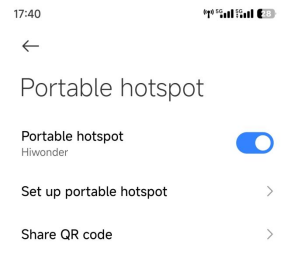
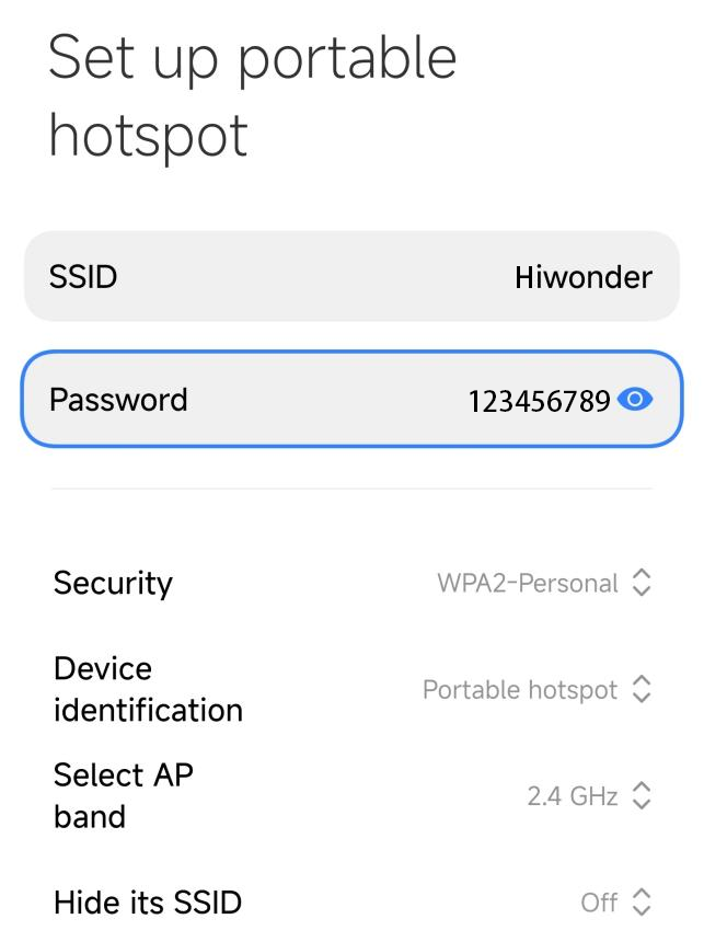
(1) Set up a hotspot on your smartphone and make a note of the hotspot name (Hiwonder) and password (123456789).
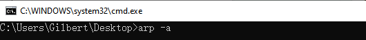
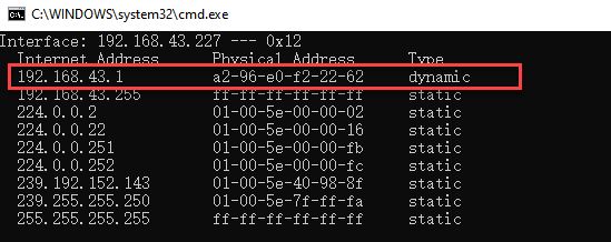
(2) Connect your computer to the smartphone’s hotspot. Once connected, press “Win”+”R”, type “CMD” to open the Command Prompt. In the Command Prompt, enter the command “arp -a” to view the IP address of your computer.
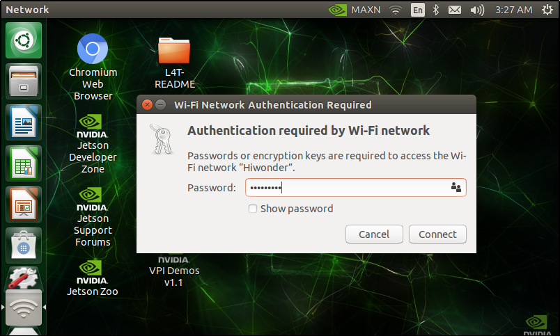
(3) After successfully connecting the computer to the Wi-Fi, power on the Jetson Nano development board and connect it to the same Wi-Fi network.
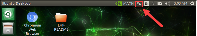
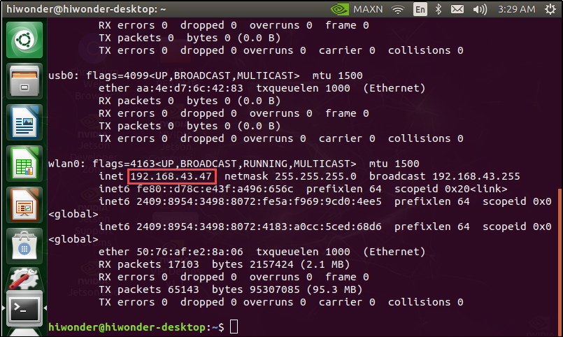
(4) Once connected, you need to obtain the Jetson Nano’s IP address. Press “Ctrl+Alt+T” to open the terminal, type “ifconfig,” and press Enter.

(5) The IP address of the development board, shown in the red box in the image below, will be “192.168.43.47.” Make a note of this IP address.
There are various other methods to check the IP address, such as accessing the router’s management interface. Users interested in alternative methods can search online for more options.
Jetson Nano Nomachine Configuration
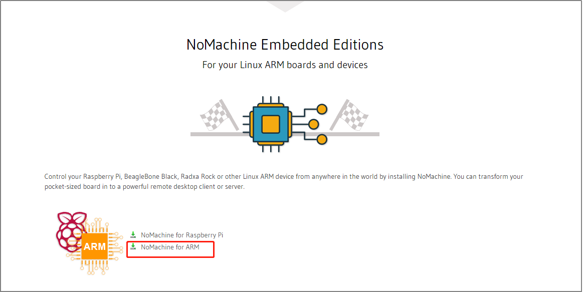
(1) Power on the Jetson Nano development board and open a web browser. Go to the following URL: https://www.nomachine.com/download to access the Nomachine download page.
On the page, find the “NoMachine for ARM” section and click to navigate to the ARM version download page.
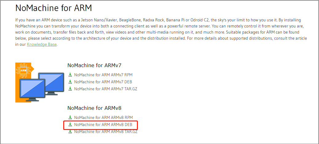
(2) Click on “NoMachine for ARM ARMv8 DEB” to proceed to the download page.
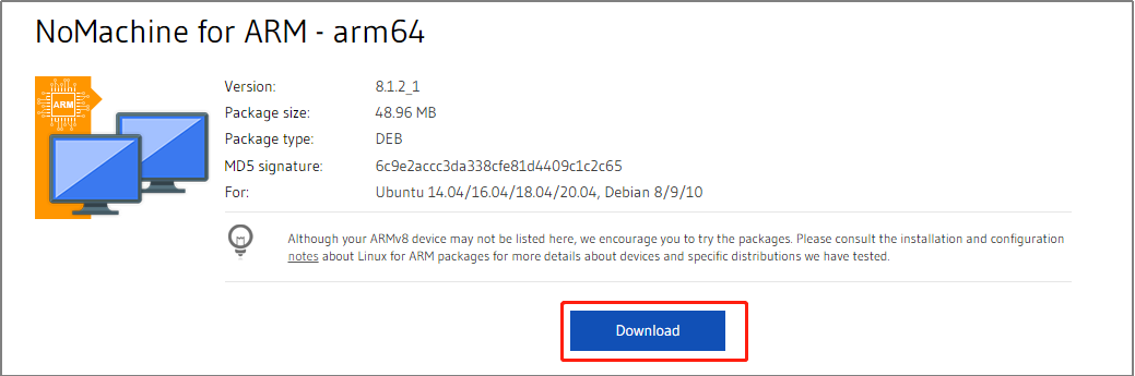
(3) Click the “Download” button to start downloading Nomachine.
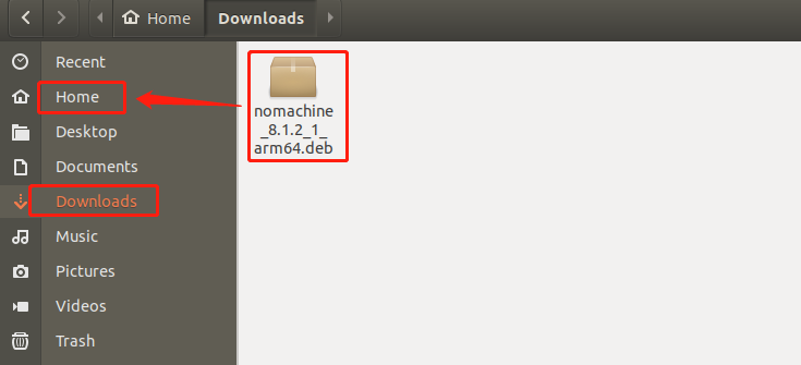
(4) Once the download is complete, move the file from the download directory to the “Home” directory.
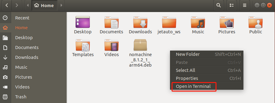
(5) In the “Home” directory, right-click and select “Open Terminal.”
(6) In the terminal, enter the following command:
sudo dpkg -i nomachine_8.1.2_1_arm64.deb
(Note: Replace nomachine_8.1.2_1_arm64.deb with the actual name of the downloaded file.) Press Enter and wait for the installation to complete.

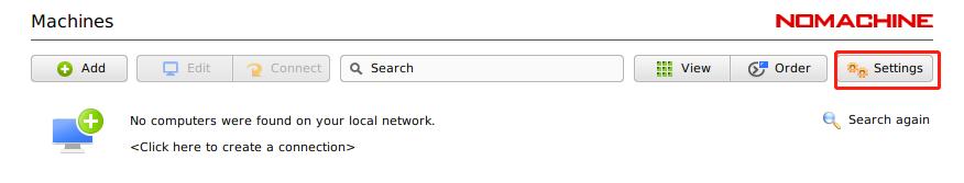
(7) After installation is finished, open Nomachine and click on “Settings” to enter the settings page.
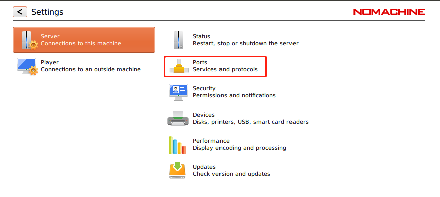
(8) Click on “Ports” to open the port settings page.
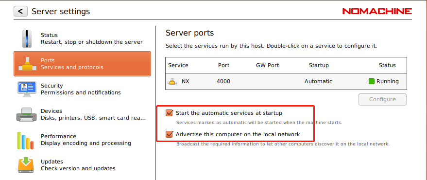
(9) Ensure that both options shown in the image below are checked. Once confirmed, the configuration is complete.
Installing and Using NoMachine on Your Computer
(1) Installation of NoMachine
① Navigate to the folder containing the installation package and double-click the NoMachine installer file “nomachine_7.1.3_1.exe.”
② Click the “Next” button to proceed.
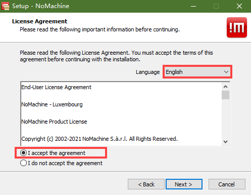
③ Choose “English” as the installation language, agree to the terms and conditions by checking the box, and click “Next.”
④ Keep the default installation location and click “Next” to continue.
⑤ Wait for the installation to complete. Once finished, click “Finish” to exit the installer.
⑥ Click “Yes” to restart your computer. (Do not skip this step!)
(2) NoMachine Usage
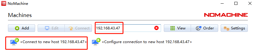
① Open NoMachine and enter the IP address “192.168.43.47” in the search bar. Click to create a connection to this address.
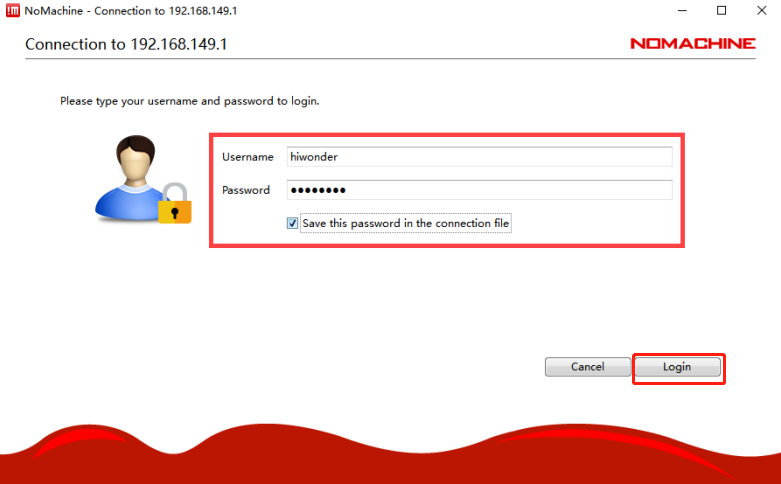
② Enter your username and password, then click the “Login” button. You will then be able to access the remote desktop of the Jetson Nano.
4.6.2 Jetson Voice Recognition
Preparation
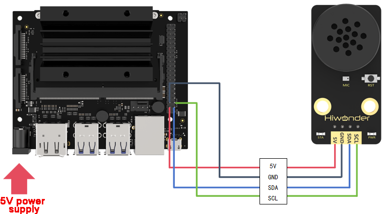
(1) Wiring Instructions
This example uses the Jetson Nano board. Connect the integrated voice module to the board’s interface as shown in the diagram.
Note
Before powering on, ensure no metal objects are in contact with the board. Metal contact with the pins on the underside of the board may cause a short circuit and potentially damage the board.
(2) Program Import and Execution
① Power on the Jetson board and connect to its remote desktop using NoMachine, following the steps in 4.6.1 Remote Connectivity and File Transfer.
② Drag the speech_recognition.py file to the Jetson desktop (or any preferred location). Once you see “Complete,” the transfer is successful.
③ Right-click on an empty area of the desktop (or the relevant folder) and select Open in Terminal.
④ Enter the following command to install the I2C device communication library. (Ensure that the Jetson board is connected to the network during installation):
sudo apt-get install python3-smbus
⑤ To run the speech recognition example, enter the following command. (If the file is not on the desktop, replace the command with the appropriate directory path):
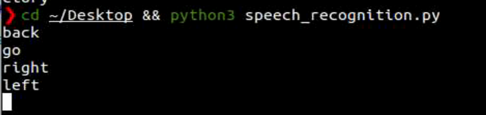
cd ~/Desktop && python3 speech_recognition.py
Test Case
This example demonstrates how the voice module recognizes specific keywords and prints the corresponding output in the terminal.
(1) Expected Results
Note
Before the module can recognize commands, you must first say “Hello Hiwonder” to wake it up. After this, it will be ready to listen for further instructions.
① When the voice interaction module detects the keyword “forward”, it will respond with “Moving forward,” and the terminal will display “go.”
② When the module detects the keyword “backward”, it will respond with “Moving backward,” and the terminal will display “back.”
③ When the module detects the keyword “left turn”, it will respond with “Turning left,” and the terminal will display “left.”
④ When the module detects the keyword “right turn”, it will respond with “Turning right,” and the terminal will display “right.”
⑤ When the module detects the keywords “stop” or “halt”, it will respond with “Received,” and the terminal will display “stop.”
The output in the terminal will look like this:
(2) Program Overview
① The program imports the smbus and time libraries to facilitate I2C communication with the voice interaction module and to manage delays.
3 4 | import smbus import time |
② The register addresses are defined for communication with the module.
6 7 8 9 10 11 | # I2C address I2C_ADDR = 0x34 # I2C address ASR_RESULT_ADDR = 100 # ASR result register address ASR_SPEAK_ADDR = 110 # ASR speaking register address ASR_CMDMAND = 0x00 ASR_ANNOUNCER = 0xFF |
③ The ASRModule class is created to establish an I2C connection with the device.
13 14 15 16 17 18 | class ASRModule: def __init__(self,address, bus=1): # Initialize I2C bus and device address self.bus = smbus.SMBus(bus) # Use I2C bus 1 self.address = address # Device's I2C address self.send = [0, 0] # Initialize the data array to be sent |
④ Several functions are defined to handle read and write operations with the integrated voice module.
⑤ In the main function, the asr_module.rec_recognition() method is used to obtain recognition results and respond accordingly. For detailed information on the returned data list.
81 82 83 84 85 86 87 88 89 90 91 92 93 94 95 | if __name__ == "__main__": asr_module = ASRModule(I2C_ADDR) while True: recognition_result = asr_module.rec_recognition() if recognition_result[0] != 0: if recognition_result[0] == 1: print("go") elif recognition_result[0] == 2: print("back") elif recognition_result[0] == 3: print("left") elif recognition_result[0] == 4: print("right") elif recognition_result[0] == 9: print("stop") |
4.6.3 Jetson Voice Broadcast
Preparation
(1) Wiring Instructions
This example uses the Jetson Nano board. Connect the integrated voice module to the Jetson board’s interface as shown in the diagram:
Note
Important: Before powering on, ensure that no metallic objects are in contact with the board. The pins on the underside of the board could cause a short circuit, potentially damaging the board.
(2) Program Import and Execution
① Power on the Jetson board as outlined in 4.6.1 Remote Connection and File Transfer, and use NoMachine to connect to the Jetson remote desktop.
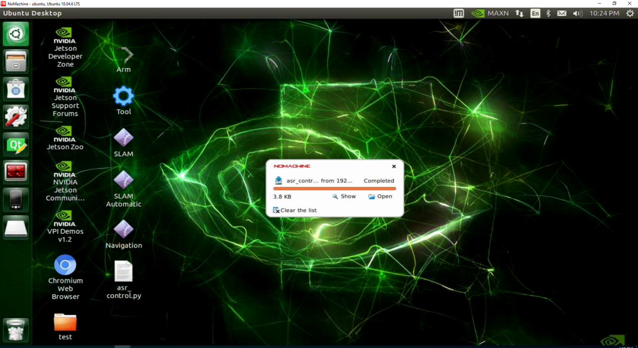
② Drag the asr_conUtrol.py file to the Jetson desktop (or any preferred location). Once the message “complete” appears, the transfer is successful.
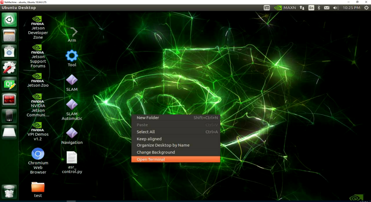
③ On the desktop (or in the corresponding directory), right-click on an empty space and select Open in Terminal.
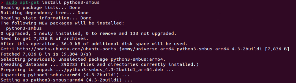
④ Enter the following command to install the I2C communication library. (Ensure the Jetson board is connected to the network during installation):
sudo apt-get install python3-smbus
⑤ To run the voice recognition example, use the following command. If the file is not on the desktop, adjust the command to the appropriate directory path:
cd ~/Desktop && python3 asr_control.py
Example Test
This example demonstrates how to control the Jetson board to make the voice interaction module play voice messages in a loop.
(1) Expected Results
The Jetson development board controls the voice interaction module to play the following messages every 5 seconds:
Moving forward
Turning left
Recyclable waste
Hazardous waste
(2) Program Overview
① The program imports the smbus and time libraries to handle I2C communication and manage delays with the voice interaction module.
3 4 | import smbus import time |
② Register addresses are defined.
19 20 21 22 23 24 25 26 | I2C_ADDR = 0x34 # I2C address # The recognition results are stored at this address. Continuously monitoring its value indicates whether speech has been detected, with each value corresponding to a specific voice command. ASR_RESULT_ADDR = 0x64 ASR_SPEAK_ADDR = 0x6E ASR_CMDMAND = 0x00 ASR_ANNOUNCER = 0xFF |
③ The ASRModule class is created to establish communication with the device via the I2C bus.
28 29 30 31 32 33 | class ASRModule: def __init__(self,address, bus=1): # Initialize the I2C bus and device address self.bus = smbus.SMBus(bus) # Use I2C bus 1 self.address = address # I2C address of the device self.send = [0, 0] # Initialize the data array for transmission |
④ Various functions are defined for writing and reading data from the integrated voice module.
⑤ In the main function, the program controls the voice module to announce phrases every 5 seconds.
96 97 98 99 100 101 102 103 104 105 106 107 108 109 | if __name__ == "__main__": asr_module = ASRModule(I2C_ADDR) # Define the speech content and its corresponding ID announcements = [ (ASR_CMDMAND, 1), # Moving forward (ASR_CMDMAND, 3), # Turning left (ASR_ANNOUNCER, 1), # Recyclable materials (ASR_ANNOUNCER, 3) # Hazardous waste ] while True: for cmd, id in announcements: asr_module.speak(cmd, id) time.sleep(5) |
⑥ ASR_CMDMAND is defined as a macro with the value 0x00, indicating that the operation is a command word. The value 1 is written to the ASR_CMDMAND register, triggering the message “Moving forward,” while 3 corresponds to the message “Turning left.”
⑦ ASR_ANNOUNCER, with a value of 0xFF, indicates that the operation is an announcement phrase. Writing 1 to the ASR_ANNOUNCER register triggers the message “Recyclable materials,” while 3 corresponds to “Hazardous waste.”
⑧ For the full list of data values, please refer to the Command Word Broadcasting Protocol List.
4.7 Scratch Communication
4.7.1 Scratch Voice Recognition
Preparation
(1) Wiring Instructions
Use a 4-pin cable to connect the voice interaction module to interface 3 on the CoreX controller.

Note
Before powering on, make sure there are no metal objects in contact with the controller. Otherwise, the pins at the bottom of the board may cause a short circuit, potentially damaging the board.
(2) Scratch Program Download
① Connect the CoreX controller to the computer using a data cable.
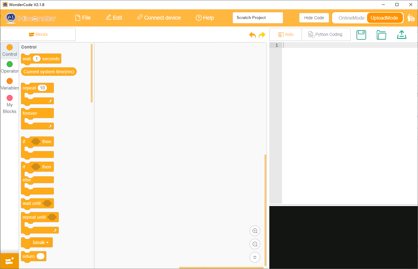
② Launch the WonderCode software 
③ Drag the “02 Voice Broadcasting Program.sb3” file (located in the same directory as this document) into the WonderCode interface.
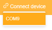
④ Click on the “Connect” option in the menu bar and select the correct COM port (e.g., COM7). Once the connection is successful, a “Connection Successful” message will appear.

⑤ Click the “Upload”  button on the right to transfer the program to the device. Wait for the “Download Successful” prompt to confirm the process is complete.

Test Case
This example demonstrates how the CoreX controller retrieves the recognition results from the voice interaction module and prints them via the serial port.
(1) Implementation Effect
Note
This example demonstrates how the CoreX controller retrieves the recognition results from the voice interaction module and prints them via the serial port.
① When the voice interaction module recognizes the “forward” command, it will respond with “Moving forward,” and the serial port will print “go.”
② When the voice interaction module recognizes the “backward” command, it will respond with “Moving backward,” and the serial port will print “back.”
③ When the voice interaction module recognizes the “turn left” command, it will respond with “Turning left,” and the serial port will print “left.”
④ When the voice interaction module recognizes the “turn right” command, it will respond with “Turning right,” and the serial port will print “right.”
⑤ When the voice interaction module recognizes the “stop” or “halt” command, it will respond with “Acknowledged,” and the serial port will print “stop.”
The printed data will be as follows:

(2) Program Overview
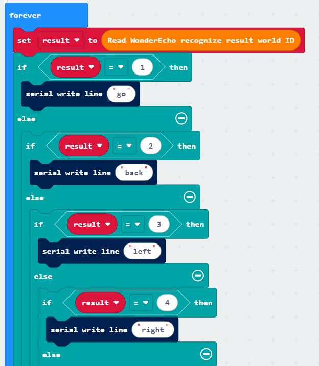
① Upon program startup, the interface for the WonderEcho module is initialized to Interface 3.

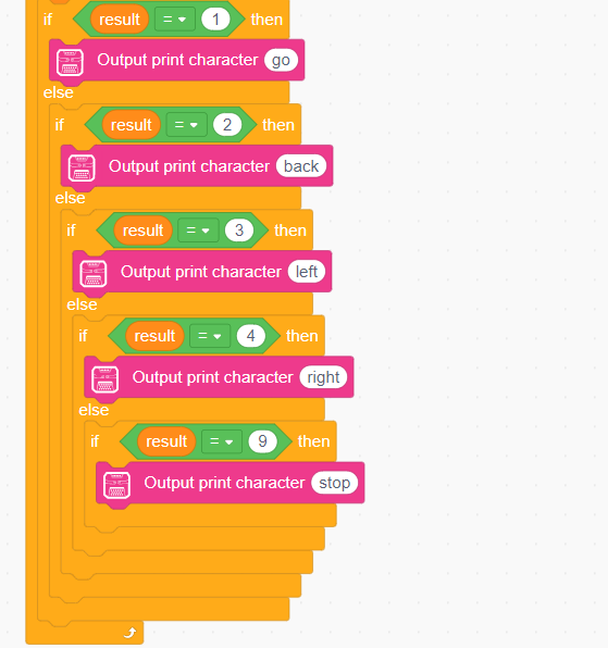
② In the main loop, the program first retrieves the command ID recognized by the WonderEcho module.

③ When the module recognizes the “forward” command, it returns 0x01. If it recognizes the “backward” command, it returns 0x02. Similarly, each recognized command returns its corresponding command ID, which is printed via the serial port. For a detailed list of the returned data, please refer to the Command Word Broadcasting Protocol List section.
4.7.2 Scratch Voice Broadcast
Preparation
(1) Wiring Instructions
Use a 4-pin cable to connect the voice interaction module to interface 3 on the CoreX controller.
Note
Before powering on, make sure there are no metal objects in contact with the controller. Otherwise, the pins at the bottom of the board may cause a short circuit, potentially damaging the board.
(2) Scratch Program Download
① Connect the CoreX controller to the computer using a data cable.
② Launch the WonderCode software
③ Drag the 02 Voice Announcement Program.sb3 file (located in the same directory as this document) into the WonderCode interface.
④ Click on the “Connect” option in the menu bar and select the correct COM port (e.g., COM7). Once the connection is successful, a “Connection Successful” message will appear.
⑤ Click the “Upload” button on the right to transfer the program to the device. Wait for the “Download Successful” prompt to confirm the process is complete.
Test Case
This example demonstrates how the CoreX controller commands the voice interaction module to loop through speech playback.
(1) Expected Outcome
The CoreX development board controls the voice interaction module to announce the following phrases every 5 seconds:
“Moving forward”
“Turning left”
“Recyclable materials”
“Hazardous waste”
(2) Program Overview
① Upon program initialization, the WonderEcho module interface is set to Interface 3.

② The program enters a loop, where it sequentially announces the following phrases:
“Moving forward” (followed by a 5-second wait),
“Turning left” (after another 5-second wait).
③ The program continues with the following announcements:
“Recyclable materials” (followed by a 5-second wait),
“Hazardous waste.”
For a detailed list of the data, please refer to the Command Word Broadcasting Protocol List section.
4.8 microbit Communication
4.8.1 microbit Voice Recognition
Note
Expansion Pack address: https://github.com/Hiwonder/WonderEcho
Preparation
(1) Wiring Instruction
Connect the voice interaction module to the micro:bit expansion board.
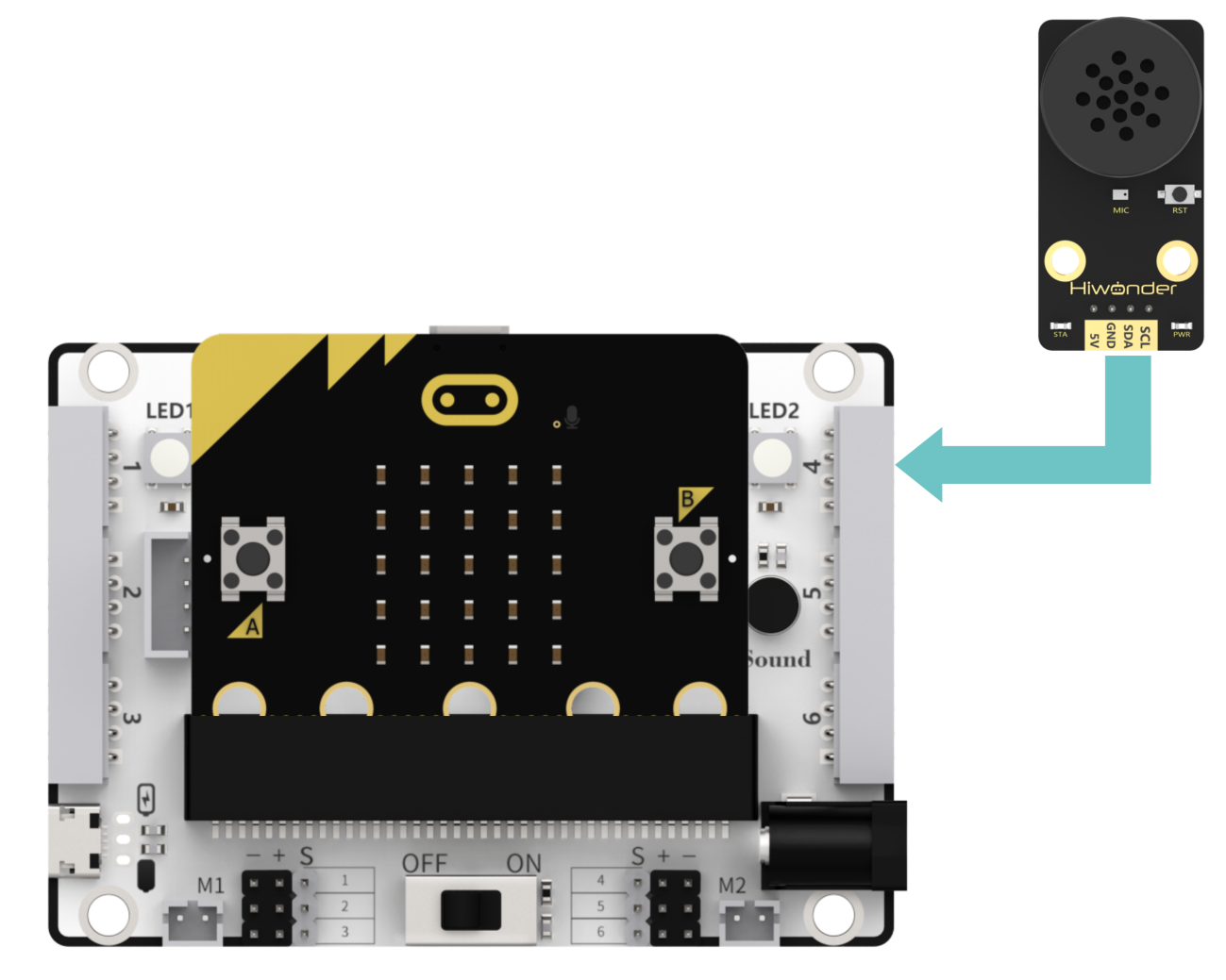
Note
Before powering on, ensure that no metal objects come into contact with the controller. Failure to do so may result in a short circuit due to the pins on the underside of the controller, potentially damaging the board.
(2) micro:bit Program Download
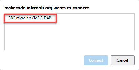
① Click-on  , and click-on ‘Connect Device’ to connect to the micro:bit controller.

② Click-on ‘Download’ to flash the programs.

③ The download completion indicator will stop flashing and remain solid, while the main interface will display a “Download Complete” notification.

Test Case
(1) Achieved Effect
Note
Before recognition, you must first say “Hello Hiwonder” to wake up the module, enabling it to perform recognition.
① When the voice interaction module recognizes the word “Go forward,” it will respond with “Going forward,” and the serial port will output “go.”
② When the voice interaction module recognizes the word “Go backward,” it will respond with “Going backward,” and the serial port will output “back.”
③ When the voice interaction module recognizes the word “Turn left,” it will respond with “Turning left,” and the serial port will output “left.”
④ When the voice interaction module recognizes the word “Turn right,” it will respond with “Turning right,” and the serial port will output “right.”
⑤ When the voice interaction module recognizes the word “stop” or “halt,” it will respond with “Received,” and the serial port will output “stop.”
(2) Brief Program Analysis
① Initialization: Redirect the serial port to USB for communication between the device and the computer via USB.

② Infinite Loop: Continuously read the voice recognition result IDs within the loop. Based on the ID values, send the corresponding string commands through the serial port.

4.8.2 microbit Voice Announcement
Preparation
(1) Wiring Instruction
Connect the voice interaction module to the micro:bit expansion board.
Note
Before powering on, ensure that no metal objects come into contact with the controller. Failure to do so may result in a short circuit due to the pins on the underside of the controller, potentially damaging the board.
(2) micro:bit Program Download
① Click-on , and click-on ‘Connect Device’ to connect to the micro:bit controller.
② Click-on ‘Download’ to flash the programs.
③ The download completion indicator will stop flashing and remain solid, while the main interface will display a “Download Complete” notification.
Test Case
This example program uses the micro:bit development board to make the voice interaction module play speech in a continuous loop.
(1) Achieved Effect
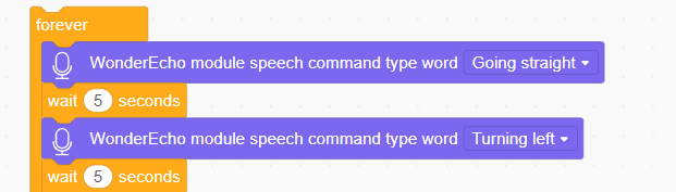
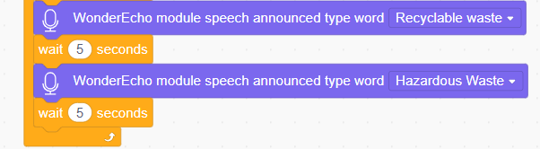
The voice interaction module announces “Going forward,” “Turning left,” “Recyclable waste,” and “Hazardous waste” in sequence every 5 seconds.
(2) Brief Program Analysis
① Within the loop function, pre-recorded phrases are set to play in sequence.