6. Secondary Development
6.1 Arduino Development
6.1.1 What is the Inverse Kinematics
This lesson aims at helping users basically learning about the principle of inverse kinematics. The further learning and practical application of the inverse kinematics of robotic arm is available in the folder “7. Inverse Kinematics Lesson”
What is it?
Forward kinematics refers to process of obtaining position and velocity of end effector, given the known joint angles and angular velocities. In other word, the position information of end effector can be obtained when then joint angle and linkages parameters are known.
Inverse Kinematics is the inverse function or algorithm of Forward Kinematics. According to the position and post of the end effector along with linkages parameters, the joint position can be calculated, i.e., Given the robot’s end-effector positions, inverse kinematics can determine an appropriate joint configuration.
(1) Establish Coordinate System
A coordinate system must be established to describe the motion of an object. MaxArm uses x-y-z axes coordinate system (unit:mm) and takes the the base centre of robotic arm as original point (0,0,0), as the figure shown below.

The correspondence relationship between the movement orientation of end effector and the values of x-y-z axes is shown below (user per se as reference):
| Coordinate axis | control orientation |
|---|---|
| x | Control the end effector of robotic arm to move left or right (As the x value is positive, it moves to the right. As the x value is negative, it moves to the left. ) |
| y | Control the end effector of robotic arm to move forward and backward. (As the y value is negative,it moves backward. As the y value is positive, it moves forward.) |
| z | Control the end effector of robotic arm to move up and down (As the z value is negative, it moves up. As the z value is positive, it moves down.) |
(2) Project Operation
After learning about the principle and spatial concept of inverse kinematics, the control method of inverse kinematics can be mastered by a simple routine. You can follow the steps below to run the game.
① Install and connect Arduino. (Please refer to the tutorial in folder “4. Underlying Files Learning–Arduino Development–Lesson 1 Set Development Environment”)
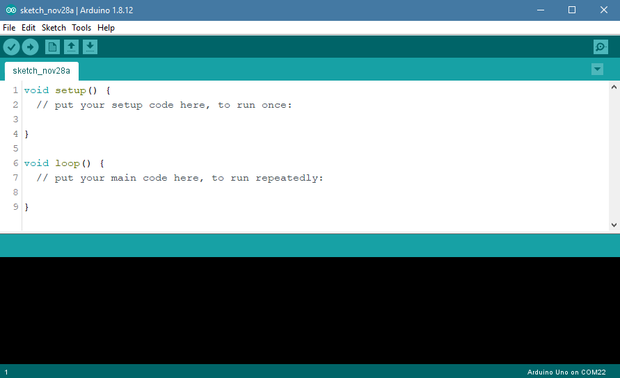
② Double click to open “Arduino IDE”  .
.

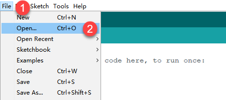
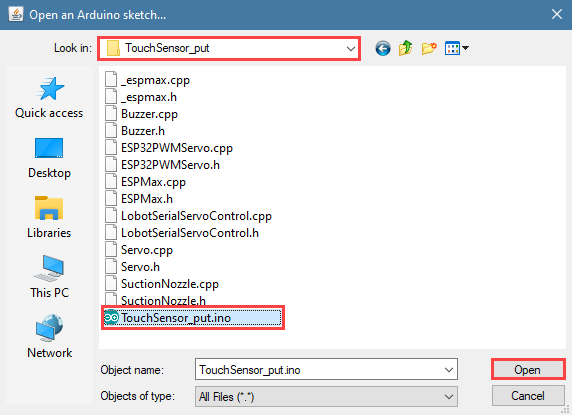
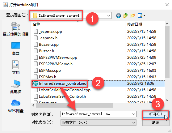
③ Click “File”–“Open”.
④ Select the program “kinematics_demo.ino” in the folder “5.MaxArm Hardware Basics Learning–Arduino Development–Game Programs–Program Files–kinematics_demo”, and click “Open”.

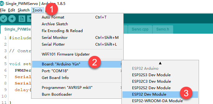
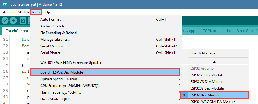
⑤ Check the board model. Click “Tools”–“Board” and select “ESP 32 Dev Module”. (If the model of development board has been configured when setting the development environment, you can skip this step.)
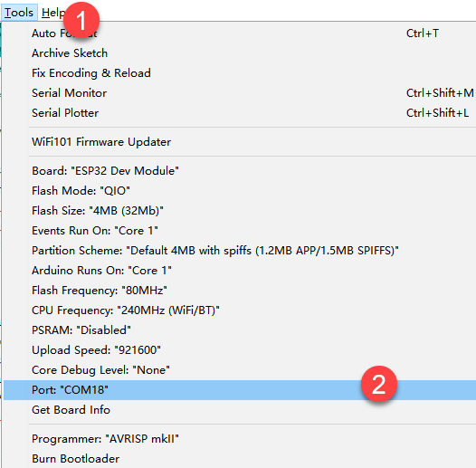
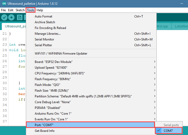
⑥ Select the corresponding port of ESP32 controller in “Tools” – “Port”. (Here take the port “COM5” as example. Please select the port based on your computer. If COM1 appears, please do not select because it is the system communication port but not the actual port of the development port.)
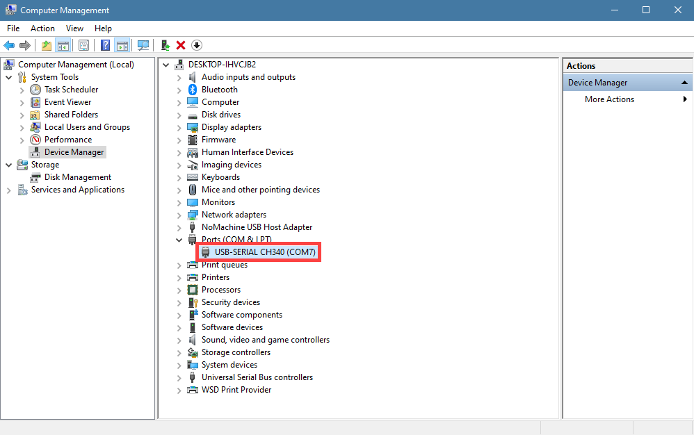
⑦ If you are not sure the port number, please open the “This PC” and click “Properties”–”Device Manger” in turns to check the corresponding port number (the device is with CH340).

⑧ After selecting, confirm the board “ESP32 Dev Module” in the lower right corner and the port number “COM5” (it is an example here, please refer to the actual situation).

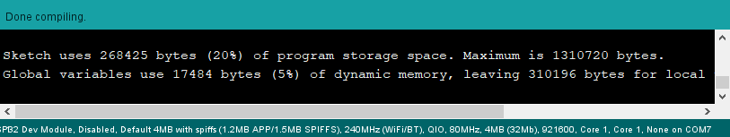
⑨ Then click on  icon to verify the program. If no error, the status area will display “Compiling”–“Compile complete” in turn. After compiling, the information such as the current used bytes, and occupied program storage space will be displayed.

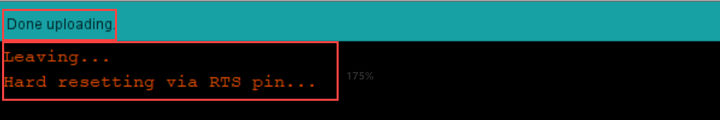
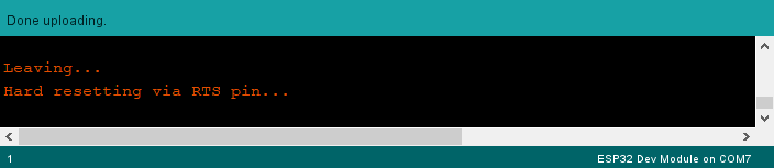
⑩ After compiling, click on  icon to upload the program to the development board. The status area will display “Compiling”–“Uploading”–“Complete” in turn. After uploading, the status area will stop printing the uploading information.
(3) Project Analysis
The complete program is as follow:
1 2 3 4 5 6 7 8 9 10 11 12 13 14 15 16 17 18 19 20 21 22 23 24 25 26 27 28 29 30 31 32 33 34 35 36 37 38 39 40 41 42 43 44 | #include "ESPMax.h" #include "_espmax.h" // Inverse kinematics basic example void setup(){ ESPMax_init(); go_home(2000); // Move the robotic arm back to the initial position Serial.begin(9600); Serial.println("start..."); } bool start_en = true; void loop(){ if(start_en){ float x,y,z; float pos[3]; // XYZ position of the robotic arm’s initial pose x = 0; y = -(L1 + L3 + L4); z = (L0 + L2); // Print XYZ position via serial, unit: millimeter Serial.print(x); Serial.print("; "); Serial.print(y); Serial.print("; "); Serial.println(z); // Since the initial position of the robotic arm is already at the edge of its reachable workspace, it must first move downward along the Z-axis. Otherwise, the arm will not be able to // move along the X or Y axes. // set_position(pos,t), pos={x,y,z}; x: X-axis coordinate, y: Y-axis coordinate, z: Z-axis coordinate, t: total movement time (the longer the time, the slower the speed) pos[0] = x; pos[1] = y; pos[2] = z-100; set_position(pos,2000); // Move Z-axis 100mm down relative to the initial position delay(2000); pos[0] = x; pos[1] = y; pos[2] = z; set_position(pos,2000); // Reset robotic arm to initial pose delay(1000); start_en = false; } else{ delay(500); // Delay 500 ms } |
① Import function library
Before the robotic arm starts to move, the encapsulation library and underlying library of inverse kinematics need to be imported.
1 2 | #include "ESPMax.h" #include "_espmax.h" |
② Calculate the initial position of robotic arm
According to the linkage parameters of L0-L4 defined in kinematics underlying library.
1 2 3 4 5 6 7 8 | #ifndef _ESPMAX_H #define _ESPMAX_H #define L0 84.4 #define L1 8.14 #define L2 128.4 #define L3 138.0 #define L4 16.8 |

Calculate the initial position of the end effector. (Use the L0-L4 values to get x=0, y=162.94, z=212.8)
18 19 20 21 | // XYZ position of the robotic arm’s initial pose x = 0; y = -(L1 + L3 + L4); z = (L0 + L2); |
③ Control robotic arm
Use the function set_position() to control the end effector to move.
Take the code set_position(pos,2000) as example.
34 35 36 37 38 39 | pos[0] = x; pos[1] = y; pos[2] = z-100; set_position(pos,2000); // Move Z-axis 100mm down relative to the initial position delay(2000); pos[0] = x; pos[1] = y; pos[2] = z; set_position(pos,2000); // Reset robotic arm to initial pose delay(1000); |
The first parameter “pos” is a set of valuea representing the position values of the end effector on x-y-z axis.
Among them, pos[0] represents the x-axis value of the initial position of the end-effector.
pos[1] represents the the y-axis value of the initial position of the end-effector.
“pos[2]” represents the end-effector moves down to 100mm. And the position of the end effector can be set by modifying the x,y and z values.
For example, if want to control the end-effector to move 200mm to the left. (its position relative to the original moves to 200mm to the left), set x value plus 200. If want to move to 200 to the right, set x-200.
If want to directly move to the set position, for example, move to 200mm on x axis, you just need to set x=200.
The second parameter “2000” is the running time and the unit is ms.
(4) Inverse kinematics library analysis
The path to the inverse kinematics library: Appendix–8. Controller Underlying Files–Arduino Development–ESPMax.cpp

① Import head file and define pin
1 2 3 | #include "ESPMax.h" #include "_espmax.h" #include "LobotSerialServoControl.h" |
Import the inverse kinematics and servo head files.
5 6 7 8 9 10 | #define SERVO_SERIAL_RX 35 #define SERVO_SERIAL_TX 12 #define receiveEnablePin 13 #define transmitEnablePin 14 HardwareSerial HardwareSerial(2); LobotSerialServoControl BusServo(HardwareSerial,receiveEnablePin,transmitEnablePin); |
Define the serial communication pin.
② Initialization
12 13 14 15 16 17 18 | float ORIGIN[3] ={ 0, -(L1 + L3 + L4), (L0 + L2)}; float positions[3]; void ESPMax_init(){ BusServo.OnInit(); HardwareSerial.begin(115200,SERIAL_8N1,SERVO_SERIAL_RX,SERVO_SERIAL_TX); } |
ORIGIN[3] is the initial position of the end effector calculating from the linkage length.
The function ESPMax_init() is used for initialization
The function BusServo.OnInit() is the servo configuration initialization. HardwareSerial.begin() is serial communication configuration. “115200” is the baud rate. “SERIAL_8N1” refers to the working mode. SERVO_SERIAL_RX is the pin number of RX port. SERVO_SERIAL_TX is the pin number of TX port.
③ Control a single servo
20 21 22 23 24 25 | int set_servo_in_range(int servo_id, int p, int duration){ if(servo_id == 3 & p < 470) p = 470; if(servo_id == 2 & p > 700) p = 700; BusServo.LobotSerialServoMove(servo_id, p, duration); return int(1); } |
The function set_servo_in_range() is used to control the movement of a single servo, and limit the position of servo ID2 and ID3. The ID3 Servo can not be less than 470 impulse and the No.4 can not be less than 700. The parameter servo_id is servo ID number and the parameter “p” is servo impulse. The parameter “duration” is the running time.
The function BusServo.LobotSerialServoMove() in BusServo library controls a single servo to move.
④ Calculate servo pulse
27 28 29 30 31 32 | float* position_to_pulses(float pos[3], float* pul){ float angles[3]; inverse(pos,angles); deg_to_pulse(angles,pul); return pul; } |
The function position_to_pulses() is used to calculate the servo pulse. The parameter “position” is position coordinate. “angles” is servo angle. “pulse” is servo pulse. Then the value of servo pulse will be returned.
The function inverse() is used to calculate the servo angle according to the coordinates.
The function deg_to_pulse() is used to calculate the servo pulse according to the servo angle.
⑤ Calculate robotic arm position
34 35 36 37 38 39 | float* pulses_to_position(float pul[3], float* pos){ float joints[3]; pulse_to_deg(pul,joints); forward(joints,pos); return pos; } |
The function pulses_to_position() is used to calculate the coordinate of robotic arm position. The parameter pul[3] is servo pulse. The coordinate of robotic arm is calculated according to the servo pulses, and then the coordinate value is returned.
⑥ The movement of robotic arm
41 42 43 44 45 46 47 48 49 50 51 52 53 54 55 56 57 | int set_position(float pos[3], int duration){ float x = pos[0]; float y = pos[1]; float z = pos[2]; if(z > 255) z = 255; if(sqrt(x*x + y*y) < 50) return int(0); float angles[3]; inverse(pos,angles); float pul[3]; deg_to_pulse(angles,pul); for(int i=0; i<3; i++){ positions[i] = pul[i]; BusServo.LobotSerialServoMove(i+1,pul[i],duration); delay(2); } return int(1); } |
The function set_position() is used to control the robotic arm to move, and add the position limit. The parameter “position” is the position coordinate and the “duration” is the running time.
Use judgement statement to limit the robotic arm position. The coordinate of z-axis can not be greater than 225. The root of the sum of the squares of the x and y axes coordinates should be greater than 50, which means the end effector should be outside the circle with the coordinate origin as the center and the radius of 50. The unit is millimeter.
Then use “for” to control the ID1, ID2 and ID3 servos to rotate.
⑦ Back to the initial position
83 84 85 | void go_home(int duration){ set_position(ORIGIN, duration); } |
The function go_home() is used to get robotic arm back to the initial position. The parameter “duration” is the running time and the parameter self.set_position() is to control robotic arm to move. The parameter ORIGIN is the coordinate of the initial position set in program.
⑧ Read position coordinate
93 94 95 96 97 98 99 | float* read_position(float* pos){ float pul[3]; for(int i=0; i<3; i++){ pul[i] = BusServo.LobotSerialServoReadPosition(i+1); } pulses_to_position(pul,pos); } |
Use the function self.bus_servo.get_position() to get the pulse value of servo ID1, ID2, and ID3.
Get the x,y,z position coordinate by calculating the robotic arm position function pulses_to_position(). Then the x, y and z values are obtained.
6.1.2 Ultrasonic Detection and Digital Tube Display
Ultrasonic Sensor Assembly

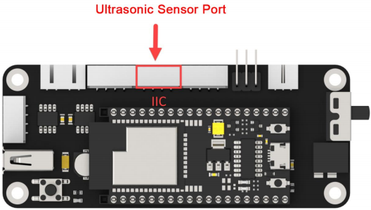
Project Principle
In this lesson, ultrasonic sensor will be used to detect object and the detection result will be displayed on digital tube.
The used glowing ultrasonic ranging module integrates ultrasonic transmitting circuits, ultrasonic receiving circuits, digital processing circuits, etc. inside the ranging chip. The module adopts IIC communication interface, and can read the measured distance through IIC communication.
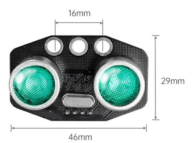
Ultrasonic sensors have two main components: the transmitter and the receiver.
The module will automatically send eight 40khz square waves and detect if there are signals are sent back. If there are signals back, output a high level. Then the duration time is time when the ultrasonic waves are sent and returns.
Measured distance(L) =(high level time* the speed of time(340M/S))/2.
The ultrasonic probes integrates two RGB lights, not only can adjust the light brightness, but also through the red (R), green (G), blue (B) three color channel changes and their superposition on each other to achieve colorful color changes.

The digital tube has a 4-digit red LED for displaying numbers, decimal points and some special characters. This module is compact and easy to use, you can apply this module in robotics projects for displaying sensor values such as speed, time, fraction, temperature, distance, etc.
Firstly, import corresponding libraries and initialize ultrasonic sensor, buzzer, servo and digital tube module.
Then set the distance measurement conditions,three threshold intervals are set in program. Different intervals is distinguished with different colors.
(1) Preparation
① Hardware
Please assemble ultrasonic sensor and digital tube to the corresponding position on MaxArm according to the tutorial in folder “Lesson 1 Module Assembly” under the same directory.
② Software
Please connect MaxArm to “Arduino IDE” according to the tutorial in folder “4. MaxArm Underlying Program Learning–Arduino Development–Lesson 1 Set Development Environment”.
(2) Program Download
① Click on  icon to open “Arduino IDE”.

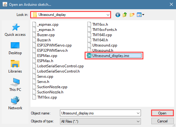
② Click “File”–“Open” in turn.

③ Open the program “Ultrasound_display.ino” in the folder “6.Secondary Development–Arduino Development–Sensor-extension Game–Program Files–Ultrasonic Detection and Digital Tube Disply–Ultrasound_display”.
④ Select the corresponding port of Arduino controller in “Tools”–“Port”. (Here take the port “COM5” as example. Please select the port based on your computer. If COM1 appears, please do not select because it is the system communication port but not the actual port of the development port.)

⑤ If you’re not sure about the port number, please open the “This PC” and click “Properties”–“Device Manger” in turns to check the corresponding port number (the device is with CH340). Then select the correct port on “Arduino IDE”.

⑥ After selecting, confirm the board “ESP32 Dev Module” in the lower right corner and the port number “COM5” (it is an example here, please refer to the actual situation).

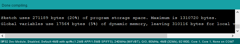
⑦ Then click on  icon to verify the program. If no error, the status area will display “Compiling”–“Compile complete” in turn. After compiling, the information such as the current used bytes, and occupied program storage space will be displayed.
⑧ After compiling, click on  icon to upload the program to the development board. The status area will display “Compiling”–“Uploading”–“Complete” in turn. After uploading, the status area will stop printing the uploading information.

(3) Project Outcome
Place a block or other objects in front of ultrasonic sensor, and then the corresponding distance will be displayed on digital tube. If the distance between sensor and object is less than 50cm, red light is on. If the distant is between 50cm and 100cm, green light is on. When the distance is farther than 100cm, blue light is on.
(4) Program Instruction
① Import Function Library
Firstly, call ultrasonic sensor library, PWM servo library, buzzer library and other related libraries.
1 2 3 4 5 | #include "ESPMax.h" #include "Buzzer.h" #include "TM1640.h" #include "Ultrasound.h" #include "SuctionNozzle.h" |
② Ultrasonic Detection
Then set variables to read the measured distance.
32 33 34 35 36 | void loop() { char text[6]; int distance = ultrasound.GetDistance(); // Read distance from ultrasound Serial.println(distance); // Print distance in mm to Serial sprintf(text, "%4d", distance); // Convert distance to string |
③ LED Display
Display the distance value on digital tube.
37 | module.setDisplayToString(text); // Display distance on digital display |
④ Light color setting
If the distance between sensor and object is less than 50cm, green light is on.
If the distant is between 50cm and 100cm, red light is on.
When the distance is farther than 100cm, blue light is on.
32 33 34 35 36 37 38 39 40 41 42 43 44 | void loop() { char text[6]; int distance = ultrasound.GetDistance(); // Read distance from ultrasound Serial.println(distance); // Print distance in mm to Serial sprintf(text, "%4d", distance); // Convert distance to string module.setDisplayToString(text); // Display distance on digital display if (distance > 0 && distance <= 50) ultrasound.Color(0, 255, 0, 0, 255, 0); //Green else if (distance > 50 && distance <= 100) ultrasound.Color(255, 0, 0, 255, 0, 0); //Red else if (distance > 100) ultrasound.Color(0, 0, 255, 0, 0, 255); //Blue delay(300); // Delay 300 ms |
6.1.3 Ultrasonic Detection and Sucking
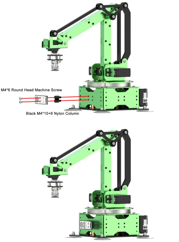
Ultrasonic Sensor Assembly
Working Principle
Ultrasonic sensors is a sensor that converts ultrasonic signals into other energy signals (usually electrical signals). There are two probes on ultrasonic sensor for receiving and transmitting ultrasound.
Firstly, import the corresponding library and initialize ultrasonic sensor, buzzer, servo and action groups.
Next, the object is detected by ultrasonic sensor and the measured distance is read by I2C protocol. After determining the distance, MaxArm will perform the corresponding action based on the determined result.
Then, execute the functions for controlling action group, starting buzzer and air pump to suck the object to the side.
The path to the source code of the program is 6.Secondary Development–Arduino Development–Sensor Development–Program Files–Ultrasonic Detection and Suction–Ultrasound_clamp–Ultrasound_clamp.ino
8 9 10 11 12 13 14 15 16 17 18 19 20 | Ultrasound ultrasound; //Instantiate Ultrasound class void setup(){ Buzzer_init(); ESPMax_init(); Nozzle_init(); Valve_on(); go_home(2000); delay(2000); Valve_off(); Serial.begin(115200); Serial.println("start..."); ultrasound.Breathing(30, 50, 60, 20, 30, 50); // Ultrasound RGB breathing mode |
(1) Preparation
① Hardware
Please assemble the ultrasonic sensor to the corresponding position on MaxArm according to the tutorial in folder “Lesson 1 Sensor Assembly” under the same directory.
② Software
Please connect MaxArm to “Arduino IDE” according to the tutorial in folder “4. Underlying Program Learning–Arduino Development–Lesson 1 Set Development Environment”.
(2) Program Download
① Click on  icon to open “Arduino IDE”.

② Click “File”–“Open” in turn.

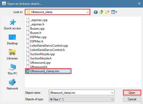
③ Select the program “Ultrasound_clamp.ino” in the folder “6.Secondary Development–Arduino Development–Sensor-extension Game–Program Files–Ultrasonic Detection and Suction–Ultrasound_clamp”.
④ Select the corresponding port of Arduino controller in “Tools”–“Port”. (Here take the port “COM5” as example. Please select the port based on your computer. If COM1 appears, please do not select because it is the system communication port but not the actual port of the development port.)
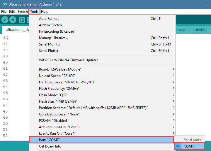
⑤ If you’re not sure about the port number, please open the “This PC” and click “Properties”–“Device Manger” in turns to check the corresponding port number (the device is with CH340). Then select the correct port on “Arduino IDE”.

⑥ After selecting, confirm the board “ESP32 Dev Module” in the lower right corner and the port number “COM5” (it is an example here, please refer to the actual situation).

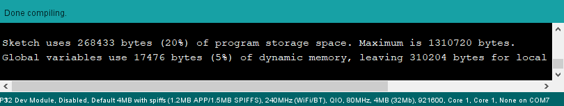
⑦ Then click on  icon to verify the program. If no error, the status area will display “Compiling”–“Compile complete” in turn. After compiling, the information such as the current used bytes, and occupied program storage space will be displayed.
⑧ After compiling, click on  icon to upload the program to the development board. The status area will display “Compiling”–“Uploading”–“Complete” in turn. After uploading, the status area will stop printing the uploading information.

(3) Project Outcome
After putting the block on the fixed detection position, the buzzer will beep after the block is detected by the ultrasonic sensor. MaxArm will move to the front of the block and start the air pump to suck it, and moves to the left. Then placing the block and stopping the air pump. Finally, MaxArm is reset.
(4) Program Instruction
① Import Library File
Firstly, the ultrasonic sensor, PWM servo, buzzer and other related library files are called.
1 2 3 4 | #include "ESPMax.h" #include "Buzzer.h" #include "Ultrasound.h" #include "SuctionNozzle.h" |
② Ultrasonic Detection
Then read the measured distance by setting the variable. To reduce errors, take the average.
25 26 27 28 29 30 31 32 | void loop(){ float pos[3]; int distance = 0; for(int i=0; i<5; i++){ distance += ultrasound.GetDistance(); //Read distance from ultrasound delay(200); } int dis = int(distance/5); //Take average value |
③ Detection Feedback
Set a distance range with another if judgement statement. When the measured distance meets the set conditions, the buzzer will sound for 100ms.
33 34 | if(60 < dis & dis < 80){ //Check if distance is within 60~80mm setBuzzer(100); //Set buzzer to sound for 100ms |
④ Control Robotic Arm
By setting the position parameter, MaxArm will carry the block to the corresponding position.
35 36 37 38 39 40 41 42 43 44 45 46 47 48 49 50 51 52 53 54 55 | pos[0] = 0;pos[1] = -160;pos[2] = 100; set_position(pos,1500); //Move above the color block delay(1500); pos[0] = 0;pos[1] = -160;pos[2] = 85; set_position(pos,800); //Suction the color block Pump_on(); //Turn on pump delay(1000); pos[0] = 0;pos[1] = -160;pos[2] = 200; set_position(pos,1000); //Lift robot arm delay(1000); pos[0] = 160;pos[1] = 0;pos[2] = 200; set_position(pos,1500); //Move above placement area delay(1500); pos[0] = 160;pos[1] = 0;pos[2] = 90+overlay*40; set_position(pos,1000); //Move to placement area delay(1000); Valve_on(); //Close pump and open valve pos[0] = 160;pos[1] = 0;pos[2] = 200; set_position(pos,1000); //Lift robot arm delay(1000); Valve_off(); //Close valve |
This section uses set_position() function to control the robotic arm. Take the code set_position(pos,1500) as example.
The first parameter “pos” represents the position of the robotic arm on x, y and z axes. Among them, pos[0] represents the coordinate of x axis, pos[1] represents the coordinate of y axis, and pos[2] represents the coordinate of z-axis.
The second parameter “1500” represents the running time and its unit is ms.
Use Pump_on() function to turn on the air pump, Valve_on() function to turn off the air pump and turn on the solenoid valve, and Valve_off() function to turn off the solenoid valve.
6.1.4 Ultrasonic Detection and Stacking
Touch Sensor Assembly
Please connect the touch sensor to IO23 IO22 port on controller with 20cm 4Pin cable,as shown in the figure below.

Working Principle
Ultrasonic sensor can convert ultrasonic signals into other energy signals (usually electrical signals). There are two probes on ultrasonic sensor for receiving and transmitting ultrasound.
The path to the source code of the program is 6.Secondary Development–Arduino Development–Program Files–Ultrasonic Detection and Stacking–Ultrasound_palletize–Ultrasound_palletize.ino.
33 34 35 36 37 38 39 40 41 42 43 44 45 46 47 48 49 50 51 52 53 54 55 56 57 | if(60 < dis & dis < 80){ //Check if distance is within 60~80mm setBuzzer(100); //Set buzzer to sound for 100ms pos[0] = 0;pos[1] = -160;pos[2] = 100; set_position(pos,1500); //Move above the color block delay(1500); pos[0] = 0;pos[1] = -160;pos[2] = 85; set_position(pos,800); //Suction the color block Pump_on(); //Turn on pump delay(1000); pos[0] = 0;pos[1] = -160;pos[2] = 200; set_position(pos,1000); //Lift robot arm delay(1000); pos[0] = 160;pos[1] = 0;pos[2] = 200; set_position(pos,1500); //Move above placement area delay(1500); pos[0] = 160;pos[1] = 0;pos[2] = 90+overlay*40; set_position(pos,1000); //Move to placement area delay(1000); Valve_on(); //Close pump and open valve pos[0] = 160;pos[1] = 0;pos[2] = 200; set_position(pos,1000); //Lift robot arm delay(1000); Valve_off(); //Close valve go_home(1500); //Reset robotic arm delay(1500); |
Firstly, import the corresponding library and initialize ultrasonic sensor, buzzer, servo and action groups.
Next, the object is detected by ultrasonic sensor and the measured distance is read by I2C protocol. After determining the distance, MaxArm will perform the corresponding action based on the determined result.
Then, execute the functions for controlling action group, buzzer and air pump to suck the detected object to the side and stack it.
(1) Preparation
① Hardware
Please assemble the ultrasonic sensor to the corresponding position on MaxArm according to the tutorial in folder “Lesson 1 Sensor Assembly” under the same directory.
② Software
Please connect MaxArm to “Arduino IDE” according to the tutorial in folder “4. Underlying Program Learning–Arduino Development–Lesson 1 Set Development Environment”.
(2) Program Download
① Click on  icon to open “Arduino IDE”.

② Click “File”–“Open” in turn.

③ Select the program “Ultrasound_palletize.ino” in the folder “6.Secondary Development–Arduino Development–Sensor-extension Game–Program Files–Ultrasonic Detection and Suction–Ultrasound_clamp”.

④ Select the model of the development board. Click “Tools”–” Board” and select “ESP 32 Dev Module” (If the model of the development board has been configured when setting the development environment, you can skip this step).

⑤ Select the corresponding port of Arduino controller in “Tools”–“Port”. (Here take the port “COM5” as example. Please select the port based on your computer. If COM1 appears, please do not select because it is the system communication port but not the actual port of the development port.)
⑥ If you’re not sure about the port number, please open the “This PC” and click “Properties”–“Device Manger” in turns to check the corresponding port number (the device is with CH340). Then select the correct port on “Arduino IDE”.

⑦ After selecting, confirm the board “ESP32 Dev Module” in the lower right corner and the port number “COM5” (it is an example here, please refer to the actual situation).

⑧ Then click on  icon to verify the program. If no error, the status area will display “Compiling”–“Compile complete” in turn. After compiling, the information such as the current used bytes, and occupied program storage space will be displayed.

⑨ After compiling, click on  icon to upload the program to the development board. The status area will display “Compiling”–“Uploading”–“Complete” in turn. After uploading, the status area will stop printing the uploading information.

(3) Project Outcome
After the block is detected by the ultrasonic sensor, the buzzer will beep once. Then, the suction nozzle will move to the block and suck it after turning on the air pump, and carry the block to the stacking area for stacking. After performing the stacking action three times, MaxArm will return to the initial posture.
(4) Program Instruction
① Import library file
The path to the source code of the program is 6.Secondary Development–Arduino Development–Sensor-extension Game–Program Files–Ultrasonic Detection and Stacking–Ultrasound_palletize–Ultrasound_palletize.ino
Before running program, the ultrasonic sensor, buzzer, PWM servo, bus servo and air pump and other related library files are called.
1 2 3 4 | #include "ESPMax.h" #include "Buzzer.h" #include "Ultrasound.h" #include "SuctionNozzle.h" |
② Ultrasonic Detection
Use the ultrasound.getDistance() function to measure the distance, and then take the average of five detected distance values.
27 28 29 30 31 | for(int i=0; i<5; i++){ distance += ultrasound.GetDistance(); //Read distance from ultrasound delay(200); } int dis = int(distance/5); //Take average value |
③ Control Robotic Arm
Determine the distance of the front object first. If the object is between 60 and 80mm, MaxArm will perform the corresponding action.
33 34 35 36 37 38 39 40 41 42 43 44 45 46 47 48 49 50 51 52 53 54 55 56 57 | if(60 < dis & dis < 80){ //Check if distance is within 60~80mm setBuzzer(100); //Set buzzer to sound for 100ms pos[0] = 0;pos[1] = -160;pos[2] = 100; set_position(pos,1500); //Move above the color block delay(1500); pos[0] = 0;pos[1] = -160;pos[2] = 85; set_position(pos,800); //Suction the color block Pump_on(); //Turn on pump delay(1000); pos[0] = 0;pos[1] = -160;pos[2] = 200; set_position(pos,1000); //Lift robot arm delay(1000); pos[0] = 160;pos[1] = 0;pos[2] = 200; set_position(pos,1500); //Move above placement area delay(1500); pos[0] = 160;pos[1] = 0;pos[2] = 90+overlay*40; set_position(pos,1000); //Move to placement area delay(1000); Valve_on(); //Close pump and open valve pos[0] = 160;pos[1] = 0;pos[2] = 200; set_position(pos,1000); //Lift robot arm delay(1000); Valve_off(); //Close valve go_home(1500); //Reset robotic arm delay(1500); |
The buzzer is controlled by using the setBuzze() function. Take the code setBuzzer(100) as example.
The first parameter “100” is the sounding time of buzzer and the unit is ms.
The robotic arm is controlled by set_position() function. Take the code set_position(pos,1000) as example.
The first parameter “pos” represents the position of the robotic arm on x, y and z axes. Among them, pos[0] represents the coordinate of x axis, pos[1] represents the coordinate of y axis, and pos[2] represents the coordinate of z-axis.
The second parameter “1000” represents the running time and its unit is ms.
6.1.5 Touch Detection and Placement
Working Principle
This lesson uses touch sensor based on the principle of capacitive sensing. After supplying the touch sensor power, the touching will be sensed when our fingers or metal touch the metal sensing plate. In the meantime, the signal terminal OUT will output low level signal, vice verse. According to this characteristics, the robotic arm can be controlled to carry out the corresponding action.
The path to the source code of the program is 6.Secondary Development–Arduino Development–Sensor Development–Program Files–Touch Detection and Placement–TouchSensor_put–TouchSensor_put.ino.
6 7 8 9 10 11 12 13 14 15 16 17 18 19 20 21 22 23 | #include "LobotSerialServoControl.h" // Touch placement #define sensor_pin 23 // Define touch sensor pin void setup(){ // Initialize libraries Buzzer_init(); ESPMax_init(); Nozzle_init(); PWMServo_init(); pinMode(sensor_pin, INPUT_PULLUP); // Set sensor pin to internal pull-up mode Serial.begin(9600); Serial.println("start..."); setBuzzer(100); // Set buzzer to sound for 100 ms go_home(2000); // Move robotic arm to initial position SetPWMServo(1,1500,2000); // Set suction nozzle servo to initial position |
Firstly, import the corresponding libraries and initialize buzzer, servo and action group.
Next, create the functions of buzzer and touch control. Set the buzzer to make sound feedback and the robotic arm to perform the corresponding action when short press the touch sensor.
Then, execute the function for controlling action, buzzer, and air pump to suck the detected object to the side and place it.
(1) Preparation
① Hardware
Please assemble the touch sensor to the corresponding position on MaxArm according to the tutorial in folder “Lesson 1 Sensor Assembly” under the same directory.
② Software
Please connect MaxArm to “Arduino IDE” according to the tutorial in folder “4. Underlying Program Learning–Arduino Development–Lesson 1 Set Development Environment”.
(2) Program Download
① Click on  icon to open “Arduino IDE”.
② Click “File”–“Open” in turn.

③ Select the program “TouchSensor_put.ino” in the folder “6.Secondary Development–Arduino Development–Sensor-extension Game–Program Files–Button Detection and Placement–TouchSensor_put”.
④ Select the model of the development board. Click “Tools”–” Board” and select “ESP 32 Dev Module” (If the model of the development board has been configured when setting the development environment, you can skip this step).

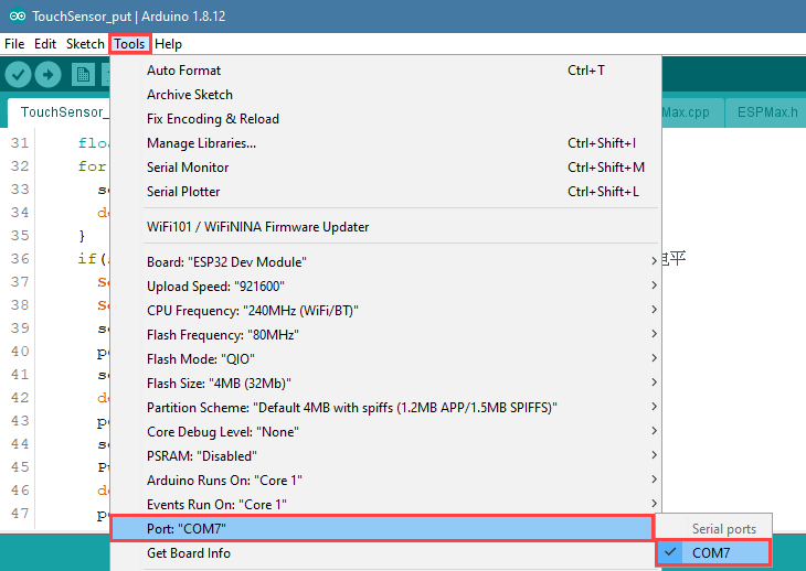
⑤ Select the corresponding port of Arduino controller in “Tools”–“Port”. (Here take the port “COM5” as example. Please select the port based on your computer. If COM1 appears, please do not select because it is the system communication port but not the actual port of the development port.)

⑥ If you’re not sure about the port number, please open the “This PC” and click “Properties”–“Device Manger” in turns to check the corresponding port number (the device is with CH340). Then select the correct port on “Arduino IDE”.

⑦ After selecting, confirm the board “ESP32 Dev Module” in the lower right corner and the port number “COM5” (it is an example here, please refer to the actual situation).

⑧ Then click on  icon to verify the program. If no error, the status area will display “Compiling”–“Compile complete” in turn. After compiling, the information such as the current used bytes, and occupied program storage space will be displayed.

⑨ After compiling, click on  icon to upload the program to the development board. The status area will display “Compiling”–“Uploading”–“Complete” in turn. After uploading, the status area will stop printing the uploading information.


(3) Project Outcome
After the buzzer beeps once, the robotic arm will suck and place the blocks in a line. When three blocks are placed completely, the buzzer will make “DiDi” sound as a feedback, and then a round of placement is finished.
(4) Program Instruction
The path to the source code of the program is 6.Secondary Development–Arduino Development–Sensor-extension Game–Program Files–Touch Detection and Placement–TouchSensor_put–TouchSensor_put.ino (The source code of the library files can be found under the same path).
If the program is modified, you can find the backup files in Appendix.
① Import Function library
Before executing the program, the Python function libraries related to the buzzer, PWM servo, bus servo and air pump need to be imported.
1 2 3 4 5 6 | #include "Buzzer.h" #include "ESPMax.h" #include "_espmax.h" #include "ESP32PWMServo.h" #include "SuctionNozzle.h" #include "LobotSerialServoControl.h" |
② Define the Pin of Sensor
Firstly, define the P23 pin of the main chip as the as the access terminal of the touch sensor.
10 | #define sensor_pin 23 // Define touch sensor pin |
③ Initialization Setting
Initialize the driver library and set the pin of sensor as pull-up mode.
12 13 14 15 16 17 18 19 20 21 22 23 | void setup(){ // Initialize libraries Buzzer_init(); ESPMax_init(); Nozzle_init(); PWMServo_init(); pinMode(sensor_pin, INPUT_PULLUP); // Set sensor pin to internal pull-up mode Serial.begin(9600); Serial.println("start..."); setBuzzer(100); // Set buzzer to sound for 100 ms go_home(2000); // Move robotic arm to initial position SetPWMServo(1,1500,2000); // Set suction nozzle servo to initial position |
④ Touch detection
When touching the metal surface of the sensor, the signal terminal will output low level and the buzzer will sound for 100ms.
36 37 38 39 | if(sensor_state == 0.0){ // Touch sensor sets pin LOW when detecting target Serial.print("num: "); Serial.println(num+1); setBuzzer(100); //Set buzzer to sound for 100 ms |
The buzzer is controlled by buzzer.setBuzze() function. Take the code buzzer.setBuzzer(100) as example.
The parameter “100” represents the sounding time of buzzer and the unit is ms.
⑤ Placement Setting
By setting the position parameter, MaxArm will transport the block to the corresponding position.
41 42 43 44 45 46 47 48 49 50 51 52 53 54 55 56 57 58 59 60 61 62 63 | set_position(pos,1500); //Move above the block delay(1500); pos[0] = 0;pos[1] = -160;pos[2] = 85; set_position(pos,800); //Suction the color block Pump_on(); //Turn on pump delay(1000); pos[0] = 0;pos[1] = -160;pos[2] = 180; set_position(pos,1000); //Lift the arm delay(1000); pos[0] = 120;pos[1] = (-20-60*num);pos[2] = 180; set_position(pos,1500); //Move above placement area Serial.println(angle_pul[num]); delay(100); SetPWMServo(1,angle_pul[num],1000); // Angle compensation to align block delay(500); pos[0] = 120;pos[1] = (-20-60*num);pos[2] = (83+num); set_position(pos,1000); //Move to placement area delay(1200); Valve_on(); //Turn off pump, open valve pos[0] = 120;pos[1] = (-20-60*num);pos[2] = 200; set_position(pos,1000); //Lift the arm delay(1000); Valve_off(); //Close valve |
This section uses arm.set_position() function to control the robotic arm to move on the set axes. Take the code set_position(pos,1500) as example.
The first parameter “pos” represents the position of the robotic arm on x, y and z axes. Among them, pos[0] represents the coordinate of x axis, pos[1] represents the coordinate of y axis, and pos[2] represents the coordinate of z-axis.
The second parameter “1500” represents the running time and its unit is ms.
The Pump_on() function is used to turn on the air pump, and the Valve_on() function is used to turn off the air pump.
6.1.6 Infrared Detection and Control
Working Principle
Infrared obstacle avoidance is a photoelectric sensor integrating IR transmitter and IR receiver. Featuring long detection distance and low interference from visible light , it is widely used in robot and assembly line piecework, etc.
This sensor detects obstacle by transmitting and receiving infrared. When the infrared transmitted by the sensor meets the obstacle ahead, the infrared will be reflected to the receiving terminal.

The path of the program file: 6.Secondary Development–Arduino Development–Sensor-extension Game–Program Files–Infrared Detection and Control–InfraredSensor_contro–InfraredSensor_control.ino
34 35 36 37 38 39 40 41 42 43 44 45 46 47 48 49 50 51 52 53 54 55 56 57 58 59 60 61 62 | if(sensor_state == 0.0){ // Infrared sensor detects target, pin goes low setBuzzer(100); //Set buzzer to sound for 100ms pos[0] = 0;pos[1] = -160;pos[2] = 100; set_position(pos,1500); //Move above the color block delay(1500); pos[0] = 0;pos[1] = -160;pos[2] = 85; set_position(pos,800); //Suction the color block Pump_on(); //Turn on the pump delay(1000); pos[0] = 0;pos[1] = -160;pos[2] = 200; set_position(pos,1000); //Lift the arm delay(1000); pos[0] = 70;pos[1] = -150;pos[2] = 200; set_position(pos,800); //Move above the placement area delay(800); SetPWMServo(1, 2200, 500); delay(200); pos[0] = 70;pos[1] = -150;pos[2] = 90; set_position(pos,800); //Move to placement area delay(800); pos[0] = 130;pos[1] = -150;pos[2] = 88; set_position(pos,500); //Push slightly to the left delay(500); Valve_on(); //Close the pump, open the solenoid valve pos[0] = 130;pos[1] = -150;pos[2] = 200; set_position(pos,1000); //Lift the arm delay(1000); Valve_off(); //Close the solenoid valve go_home(1500); |
When the sensor detects this signal, it will send it to the microcontroller for processing. The closer the obstacle is, the stronger the reflection intensity; the farther the obstacle is, the weaker the reflection intensity. Different surface color has different reflection intensity. White is the strongest and black is the weakest.
Then, the object is detected by the infrared sensor and buzzer will make sound. MaxArm will perform the corresponding action.
Finally, execute the function for controlling action, buzzer, air pump to suck and place the object.
(1) Preparation
① Hardware
Please assemble the infrared sensor to the corresponding position on MaxArm according to the tutorial in folder “Lesson 1 Sensor Assembly” under the same directory.
② Software
Please connect MaxArm to “Arduino IDE” according to the tutorial in folder “4. Underlying Program Learning–Arduino Development–Lesson 1 Set Development Environment”.
(2) Program Download
① Click on  icon to open “Arduino IDE”.

② Click “File”–“Open” in turn.

③ Select the program “InfraredSensor_control.ino” in the folder “6.Secondary Development–Arduino Development–Sensor-extension Game–Program Files–Infrared Detection and Control–InfraredSensor_control”.

④ Select the model of the development board. Click “Tools”–” Board” and select “ESP 32 Dev Module” (If the model of the development board has been configured when setting the development environment, you can skip this step).

⑤ Select the corresponding port of Arduino controller in “Tools”–“Port”. (Here take the port “COM5” as example. Please select the port based on your computer. If COM1 appears, please do not select because it is the system communication port but not the actual port of the development port.)
⑥ If you’re not sure about the port number, please open the “This PC” and click “Properties”–“Device Manger” in turns to check the corresponding port number (the device is with CH340). Then select the correct port on “Arduino IDE”.

⑦ After selecting, confirm the board “ESP32 Dev Module” in the lower right corner and the port number “COM5” (it is an example here, please refer to the actual situation).

⑧ Then click on  icon to verify the program. If no error, the status area will display “Compiling”–“Compile complete” in turn. After compiling, the information such as the current used bytes, and occupied program storage space will be displayed.
⑨ After compiling, click on  icon to upload the program to the development board. The status area will display “Compiling”–“Uploading”–“Complete” in turn. After uploading, the status area will stop printing the uploading information.

(3) Project Outcome
When the colored block is detected by infrared sensor, the robotic arm will move to the block and suck it, then transfer and place the block to the placement area. Finally, turn off the air pump.
(4) Program Instruction
① Import and Initialize
The path to the source code of the program is 6.Secondary Development–Arduino Development–Sensor-extension Game–Program Files–Infrared Detection and Control–InfraredSensor_contro–InfraredSensor_control.ino (The source code of the library files can be found under the same path).
If the program is modified, you can find the backup files in Appendix.
Before running the program, the buzzer, kinematics, kinematics encapsulation library, PWM servo, suction nozzle and other related library files need to be imported.
1 2 3 4 5 6 | #include "Buzzer.h" #include "ESPMax.h" #include "_espmax.h" #include "ESP32PWMServo.h" #include "SuctionNozzle.h" #include "LobotSerialServoControl.h" |
Then, initialize the library file and the robotic arm.
10 11 12 13 14 15 16 17 18 19 20 21 22 23 24 | #define sensor_pin 23 // Define the infrared sensor pin void setup(){ // Initialize driver libraries Buzzer_init(); ESPMax_init(); Nozzle_init(); PWMServo_init(); pinMode(sensor_pin, INPUT_PULLUP); // Set sensor pin to internal pull-up mode Serial.begin(115200); Serial.println("start..."); setBuzzer(100); // Set buzzer to sound for 100ms go_home(2000); // Move the arm to the initial position SetPWMServo(1,1500,2000); // Set suction nozzle servo to initial position } |
② Infrared Detection
Use the digitalRead() function to read the detected value of the infrared sensor and then use the for() function to detect several times.
When the object is detected by infrared sensor, sensor_pin is 0, otherwise, it is 1. Then the value of the detected value plus sensor_state is assigned to sensor_state. If the sensor_state is equal to 0.0 after five rounds, the object is detected, otherwise, no object is detected.
26 27 28 29 30 31 32 33 | void loop(){ float pos[3]; // Multiple detections float sensor_state = 0.0; for(int i=0; i<5; i++){ sensor_state += digitalRead(sensor_pin); delay(50); // Delay 50ms } |
③ Control Robotic Arm
When the object is detected by infrared sensor, MaxArm will perform the corresponding action.
34 35 36 37 38 39 40 41 42 43 44 45 46 47 48 49 50 51 52 53 54 55 56 57 58 59 60 61 62 | if(sensor_state == 0.0){ // Infrared sensor detects target, pin goes low setBuzzer(100); //Set buzzer to sound for 100ms pos[0] = 0;pos[1] = -160;pos[2] = 100; set_position(pos,1500); //Move above the color block delay(1500); pos[0] = 0;pos[1] = -160;pos[2] = 85; set_position(pos,800); //Suction the color block Pump_on(); //Turn on the pump delay(1000); pos[0] = 0;pos[1] = -160;pos[2] = 200; set_position(pos,1000); //Lift the arm delay(1000); pos[0] = 70;pos[1] = -150;pos[2] = 200; set_position(pos,800); //Move above the placement area delay(800); SetPWMServo(1, 2200, 500); delay(200); pos[0] = 70;pos[1] = -150;pos[2] = 90; set_position(pos,800); //Move to placement area delay(800); pos[0] = 130;pos[1] = -150;pos[2] = 88; set_position(pos,500); //Push slightly to the left delay(500); Valve_on(); //Close the pump, open the solenoid valve pos[0] = 130;pos[1] = -150;pos[2] = 200; set_position(pos,1000); //Lift the arm delay(1000); Valve_off(); //Close the solenoid valve go_home(1500); //Reset the arm to initial position |
The buzzer is controlled by setBuzze() function. Take the code setBuzzer(100) as example.
The parameter “100” is the sounding time of the buzzer and the unit is ms.
The robotic arm is controller by set_position() function. Take the code set_position(pos,1500) as example.
The first parameter “pos” represents the position of the robotic arm on x, y and z axes. Among them, pos[0] represents the coordinate of x axis, pos[1] represents the coordinate of y axis, and pos[2] represents the coordinate of z-axis.
The second parameter “1500” is the running time and the unit is ms.
Use Pump_on() function to turn on the air pump, Valve_on() function to turn off the air pump,and Valve_off() function to turn off the solenoid valve.
Finally, use go_home() function to make robotic arm return to the initial posture. Take the code go_home(1500) as example.
The parameter “1500” is the time for the robotic arm to reset and the unit is ms.
6.1.7 Dual Infrared Detection and Sorting
Working Principle
Infrared obstacle avoidance is a photoelectric sensor integrating IR transmitter and IR receiver. Featuring long detection distance and low interference from visible light , it is widely used in robot and assembly line piecework, etc.
This sensor detects obstacle by transmitting and receiving infrared. When the infrared transmitted by the sensor meets the obstacle ahead, the infrared will be reflected to the receiving terminal.
The path of the program file: “6.Secondary Development–Sensor-extension Game–Arduino Development–Program Files–Dual Infrared Detection and Sorting–InfraredSensor_sorting–InfraredSensor_sorting.ino”
34 35 36 37 38 39 40 41 42 43 44 45 46 47 48 49 50 51 52 53 54 55 56 57 58 | if (sensor_left == 0.0) { // Left sensor detects target, pin goes low Serial.println("infrared_left"); setBuzzer(100); //Set buzzer to sound for 100ms pos[0] = 70; pos[1] = -165; pos[2] = 120; set_position(pos, 1500); //Move above the color block delay(1500); pos[0] = 70; pos[1] = -165; pos[2] = 86; set_position(pos, 800); //Suction the color block Pump_on(); //Turn on the pump delay(1000); pos[0] = 70; pos[1] = -165; pos[2] = 200; set_position(pos, 1000); //Lift the arm delay(1000); pos[0] = 150; pos[1] = -35; pos[2] = 200; set_position(pos, 800); //Move above placement area delay(800); SetPWMServo(1, 1800, 500); |
When the signal is detected by infrared sensors, it will travel to microcontroller for processing. The closer the obstacle is, the stronger the reflection intensity; the farther the obstacle is, the weaker the reflection intensity. Different surface color has different reflection intensity. White is the strongest and black is the weakest.
Then, the object is detected by the infrared sensor and buzzer will make sound. MaxArm will perform the corresponding action.
Finally, execute the function for controlling action, buzzer, air pump to pick up and place the object.
Note
For better recognition effect, the sensitive of infrared sensor will be adjusted high, but also more susceptible to the impact of objective factors such as ambient light. If you need to adjust the sensitivity, you can refer to the content in “6. Sensitivity Adjustment” in this lesson.
(1) Preparation
① Hardware
Please refer to “Lesson 1 Sensor Assembly” to assemble infrared sensors to the corresponding position on MaxArm.
② Software
Please connect MaxArm to “Arduino IDE” according to the tutorial in folder “4. Underlying Program Learning–Arduino Development–Lesson 1 Set Development Environment”.
(2) Program Download
① Click on  icon to open “Arduino IDE”.

② Click “File”–“Open” in turn.

③ Open the program “InfraredSensor_sorting.ino” in the folder “6.Secondary Development–Arduino Development–Sensor-extension Game–Program Files–Dual Infrared Detection and Sorting–InfraredSensor_sorting.”

④ Select the model of the development board. Click “Tools”–” Board” and select “ESP 32 Dev Module” (If the model of the development board has been configured when setting the development environment, you can skip this step).

⑤ Select the corresponding port of Arduino controller in “Tools”–“Port”. (Here take the port “COM5” as example. Please select the port based on your computer. If COM1 appears, please do not select because it is the system communication port but not the actual port of the development port.)

⑥ If you’re not sure about the port number, please open the “This PC” and click “Properties”–“Device Manger” in turns to check the corresponding port number (the device is with CH340). Then select the correct port on “Arduino IDE”.
⑦ After selecting, confirm the board “ESP32 Dev Module” in the lower right corner and the port number “COM5” (it is an example here, please refer to the actual situation).

⑧ Then click on  icon to verify the program. If no error, the status area will display “Compiling”–“Compile complete” in turn. After compiling, the information such as the current used bytes, and occupied program storage space will be displayed.

⑨ After compiling, click on  icon to upload the program to the development board. The status area will display “Compiling”–“Uploading”–“Complete” in turn. After uploading, the status area will stop printing the uploading information.
(3) Project Outcome
When the block is detected, MaxArm will rotate to the corresponding position and turn on air pump to pick up the block, and then place it to placement area in the same side. After the whole process is done, turn off the air pump.
Note
If there are blocks placed in front of the two infrared sensors, according to the program setting, MaxArm will first pick up the color block on the left side (Take robot arm as the first person view).
(4) Program Instruction
① Import function library and Initialize
The path of the program file: “6. Secondary Development–Arduino Development–Program Files–Dual Infrared Detection and Sorting–InfraredSensor_sorting–InfraredSensor_sorting.ino”. If the program is modified, you can find a backup file in Appendix.
Before running the program, the buzzer, kinematics, kinematics encapsulation library, PWM servo, suction nozzle and other related library files need to be imported first.
1 2 3 4 5 6 | #include "Buzzer.h" #include "ESPMax.h" #include "_espmax.h" #include "ESP32PWMServo.h" #include "SuctionNozzle.h" #include "LobotSerialServoControl.h" |
Then, initialize the library file and the robotic arm.
10 11 12 13 14 15 16 17 18 19 20 21 22 23 24 25 26 | #define infrared_left 23 // Define left infrared sensor pin #define infrared_right 32 // Define right infrared sensor pin void setup() { // Initialize driver libraries Buzzer_init(); ESPMax_init(); Nozzle_init(); PWMServo_init(); pinMode(infrared_left, INPUT_PULLUP); // Set sensor pin to internal pull-up mode pinMode(infrared_right, INPUT_PULLUP); Serial.begin(115200); Serial.println("start..."); setBuzzer(100); // Set buzzer to sound for 100ms go_home(2000); // Move the arm to initial position SetPWMServo(1, 1500, 2000); // Set suction nozzle servo to initial position } |
② Infrared Detection
Use the digitalRead() function to read the detected value and use the for() function to detect several times to get accurate result. Take the left infrared sensor as example. When object is detected by the left infrared sensor, infrared_left is 0, otherwise, it is 1. Then the detected value plus sensor_left is assigned to sensor_left. If the sensor_left is equal to 0.0 after five rounds, the object is detected, otherwise, no object is detected.
28 29 30 31 32 33 34 35 36 37 38 | void loop() { float pos[3]; // Multiple detections float sensor_left = 0.0; float sensor_right = 0.0; for (int i = 0; i < 5; i++) { sensor_left += digitalRead(infrared_left); //Read left sensor value sensor_right += digitalRead(infrared_right); delay(50); // Delay 50ms } |
③ Infrared Detection Feedback
When an object is detected by infrared sensor, MaxArm will execute the corresponding action. Here take the left infrared sensor for example.
40 41 42 43 44 45 46 47 48 49 50 51 52 53 54 55 56 57 58 59 60 61 62 63 64 65 66 67 68 69 70 71 72 73 74 75 76 77 78 79 80 81 82 83 84 85 86 | if (sensor_left == 0.0) { // Left sensor detects target, pin goes low Serial.println("infrared_left"); setBuzzer(100); //Set buzzer to sound for 100ms pos[0] = 70; pos[1] = -165; pos[2] = 120; set_position(pos, 1500); //Move above the color block delay(1500); pos[0] = 70; pos[1] = -165; pos[2] = 86; set_position(pos, 800); //Suction the color block Pump_on(); //Turn on the pump delay(1000); pos[0] = 70; pos[1] = -165; pos[2] = 200; set_position(pos, 1000); //Lift the arm delay(1000); pos[0] = 150; pos[1] = -35; pos[2] = 200; set_position(pos, 800); //Move above placement area delay(800); SetPWMServo(1, 1800, 500); delay(200); pos[0] = 150; pos[1] = -35; pos[2] = 90; set_position(pos, 800); //Move to placement area delay(800); pos[0] = 150; pos[1] = 10; pos[2] = 88; set_position(pos, 500); //Move slightly to place delay(500); Valve_on(); //Close pump, open solenoid valve pos[0] = 150; pos[1] = 10; pos[2] = 200; set_position(pos, 1000); //Lift the arm delay(1000); Valve_off(); //Close solenoid valve go_home(1500); //Reset arm to initial position delay(200); SetPWMServo(1, 1500, 500); delay(1500); |
Take setBuzze() function, set_position() function, Pump_on() function and go_home() for example.
The setBuzze() is a function to control buzzer. Call “Buzzer.h” function in the same directory as “InfraredSensor_sorting.ino” program. Fill in the parentheses with the duration time of buzzer, and the unit is ms. The code setBuzzer(100) means that the buzzer will respond for 100ms after the infrared sensor detects an object, and then the next set_potision() function will be executed.
42 | setBuzzer(100); //Set buzzer to sound for 100ms |
The set_position() is a function to call robotic arm. Call “ESPMax.h” function in the same folder as “InfraredSensor_sorting.ino” program. Fill in the parentheses with the coordinate values and duration time. Take the code set_position(pos,1500) for example, pos[0], pos[1], pos[2] is the representative of the robot arm corresponding to the position on the XYZ axis, 1500 is the running time, the unit is milliseconds (ms). After that, the Pump_on() function is executed in the next step.
43 44 45 46 | pos[0] = 70; pos[1] = -165; pos[2] = 120; set_position(pos, 1500); //Move above the color block |
The Pump_on() is a function to control air pump. Pump_on() function is to control the air pump on; Valve_on() function is used to turn off air pump and open solenoid valve; Valve_off() function to turn off the solenoid valve. Call “InfraredSensor_sorting.ino” function in the same folder as the “SuctionNozzle.h” function, after the implementation of the next go_home() function.
52 | Pump_on(); //Turn on the pump |
76 | Valve_on(); //Close pump, open solenoid valve |
82 | Valve_off(); //Close solenoid valve |
The go_home() is a function to reset robotic arm. Cal “ESPMax.h” function in the same folder as “InfraredSensor_sorting.ino” function.Fill in the parentheses with the action duration time, and the unit is ms. Take the code go_home(1500) for example. The parameter “1500” is the time it takes to complete the reset action. When this function is finished, the program will execute 1500ms delay function and then end this recognition and sorting actions and wait for the next recognition signal.
83 | go_home(1500); //Reset arm to initial position |
(5) Adjust Sensitivity
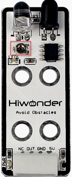
There is an adjustable potentiometer knob on infrared obstacle avoidance sensor for adjusting the measuring distance. When performing the related games, if the measurement effect it not good enough, the measurement sensitivity of sensor can be adjusted by adjusting the knob.
It is recommended to use phillips screwdriver. Rotate the knob clockwise, as the figure shown below, to increase the infrared emission intensity and the measurement distance; rotate it counterclockwise to weaken the infrared emission intensity and decrease the measurement distance.
Please take notice of the following two tips:
① Since the warm light (incandescent light, sunlight, etc) contains more infrared component, there will be a certain interference between infrared to affect the detection outcome. When using it, special attention should be paid to the surrounding environment. Therefore, you can not adjust the sensitivity alone.
② The sensitivity adjustment has is set a threshold, which you can regard it as a critical point. If the sensitivity exceeds the critical point, its value will return to the initial state.
③ Sensitivity adjustment needs to be based on the actual needs of the project. It is better to be adjusted to the most suitable conditions.
6.1.8 Color Recognition
Working Principle
The color sensor is a sensor with various functions such as recognizing the color of objects, detecting the brightness of the surrounding environment, realizing object proximity detection and non-contact gesture detection, etc.
This lesson will use the color sensor for recognizing and comparing the RGB value of object. These sensors generally determine whether the detected color is consistent with the set one by using RGB (red, green, and blue) LED light sources and the ratio of R, G, and B wavelengths in the reflected light of an object.
The path of the program file: “6.Secondary Development–Sensor-extension Game–Arduino Development–Program Files–Color Recognition–Color_Detect–Color_Detect.ino”
66 67 68 69 70 71 72 73 74 75 76 77 78 79 80 81 82 83 84 85 86 87 88 89 | void loop() { if (ColorDetect()) { // Check if the color sensor detects a color float color_num = 0.0; for (int i = 0; i < 5; i++) { color_num += ColorDetect(); // Multiple detections to avoid misreading delay(80); } color_num = color_num / 5.0; // Take the average of the results; if not integer, detection is unstable if (color_num == 1.0) { Serial.println("Red"); // Red detected, print 'Red' ultrasound.Color(255, 0, 0, 255, 0, 0); // Turn ultrasound module red } else if (color_num == 2.0) { Serial.println("Green"); // Green detected, print 'Green' ultrasound.Color(0, 255, 0, 0, 255, 0); // Turn ultrasound module green } else if (color_num == 3.0) { Serial.println("Blue"); // Blue detected, print 'Blue' ultrasound.Color(0, 0, 255, 0, 0, 255); // Turn ultrasound module blue } else { // If result is not an integer, do nothing ultrasound.Color(255, 255, 255, 255, 255, 255); } } |
Firstly, import the corresponding libraries and initialize ultrasonic sensor and color sensor.
Then read and calculate the RGB value of the object, and print out the color result.
Finally, the ultrasonic sensor emits light of the corresponding color.
(1) Preparation
① Hardware
Please assemble the color sensor and ultrasonic sensor to the corresponding position on MaxArm according to the tutorial in folder “Lesson 1 Sensor Assembly” under the same directory.
② Software
Please connect MaxArm to “Arduino IDE” according to the tutorial in folder “4. Underlying Program Learning–Arduino Development–Lesson 1 Set Development Environment”.
(2) Program Download
① Click on  icon to open “Arduino IDE”.

② Click “File”–“Open” in turn.

③ Select the program “InfraredSensor_control.ino” in the folder “6.Secondary Development–Sensor-extension Game–Arduino Development–Program Files–Infrared Detection and Control–InfraredSensor_control”.
④ Select the model of the development board. Click “Tools”–**” Board”**and select “ESP 32 Dev Module” (If the model of the development board has been configured when setting the development environment, you can skip this step).

⑤ Select the corresponding port of Arduino controller in “Tools”–“Port”. (Here take the port “COM5” as example. Please select the port based on your computer. If COM1 appears, please do not select because it is the system communication port but not the actual port of the development port.)

⑥ If you’re not sure about the port number, please open the “This PC” and click “Properties”–“Device Manger” in turns to check the corresponding port number (the device is with CH340). Then select the correct port on “Arduino IDE”.

⑦ After selecting, confirm the board “ESP32 Dev Module” in the lower right corner and the port number “COM5” (it is an example here, please refer to the actual situation).

⑧ Then click on  icon to verify the program. If no error, the status area will display “Compiling”–“Compile complete” in turn. After compiling, the information such as the current used bytes, and occupied program storage space will be displayed.

⑨ After compiling, click on  icon to upload the program to the development board. The status area will display “Compiling”–“Uploading”–“Complete” in turn. After uploading, the status area will stop printing the uploading information.

⑩ Then click on the serial port monitor icon in the upper right corner.

⑪ Select the baud rate to “115200” in the pop-up window.

(3) Project Outcome
After the colored block is detected by the color sensor, the glowing ultrasonic sensor will emit the corresponding color light.
(4) Program Instruction
① Import Function Library
Before executing the program, the I2C protocol, ultrasonic sensor, color sensor, buzzer, PWM servo, bus servo, infrared sensor and air pump and other related Python function libraries need to be imported.
1 2 3 4 5 6 7 8 9 10 | import time from machine import Pin, I2C from Ultrasonic import ULTRASONIC from Color_sensor import COLOR from Buzzer import Buzzer from espmax import ESPMaX from PWMServo import PwMServo from BusServo import BusServo from RobotControl import RobotControl from SuctionNozzle import SuctionNozzle |
② Color detection
Use apds.readRedLight(), apds.readGreenLight() and apds.readBlueLight() functions to detect the value of RGB channel of object, and calculate.
51 52 53 54 55 56 57 58 | # Analyze the data from the color sensor c = apds.readAmbientLight() r = apds.readRedLight() g = apds.resdGreenLight() b = apds.readBlueLight() r = int(255 * (r - r_f) / (R_F - r_f)) g = int(255 * (g - g_f) / (G_F - g_f)) b = int(255 * (b - b_f) / (B_F - b_f)) |
③ Control the LED of Ultrasonic Sensor
After calculating the value of RGB channel of object color, determine the color of the object.
59 60 61 | if r > 25 and r > g and r > b: color = RED print('color: red') |
Then, the ultrasonic sensor will emit the corresponding light.
60 61 62 63 64 65 66 67 68 69 70 71 72 73 74 | color = RED print('color: red') hwsr06.setRGBValue(bytes([255,0,0,255,0,0])) elif g >25 andg > r andg > b: color = GREEN print('color: green') hwsr06.setRGBValue(bytes([0,255,0,0,255,0])) elif b > 25 and b > g and b > r: color = BLUE print('color: blue') hwsr06.setRGBValue(bytes([0,0,255,0,0,255])) else: color = 0 print('') hwsr06.setRGBValue(bytes([255,255,255,255,255,255])) |
Use hwsr06.setRGBValue(bytes()) function to control the LED of the ultrasonic sensor. Take the code hwsr06.setRGBValue(bytes([255,0,0, 255,0,0])) as example.
The first three parameters “255,0,0” are the color thresholds for the LED on the right side of the senor.
The last three parameters “255,0,0” are the color thresholds for the left LED of the sensor.
At this time, the LED emits red light.
6.1.9 Color Sorting
Working Principle
The color sensor is a sensor with various functions such as recognizing the color of objects, detecting the brightness of the surrounding environment, realizing object proximity detection and non-contact gesture detection, etc.
This lesson will use the color sensor for recognizing and comparing the RGB value of object. These sensors generally determine whether the detected color is consistent with the set one by using RGB (red, green, and blue) LED light sources and the ratio of R, G, and B wavelengths in the reflected light of an object.
The path of the program file: “6.Secondary Development–Sensor-extension Game–Arduino Development–Program Files–Color Sorting–Color_Sorting–Color_Sorting.ino”
136 137 138 139 140 141 142 143 144 145 146 147 148 149 150 151 152 153 154 155 156 157 158 159 160 161 | if (60 < dis & dis < 80) { //Check if distance is within 60~80mm if (detect_color) { setBuzzer(100); //Buzzer on 100ms delay(1000); pos[0] = 0; pos[1] = -160; pos[2] = 100; set_position(pos, 1500); //Move above block delay(1500); pos[0] = 0; pos[1] = -160; pos[2] = 85; set_position(pos, 800); //Suction the color block Pump_on(); //Turn on the pump delay(1000); pos[0] = 0; pos[1] = -160; pos[2] = 180; set_position(pos, 1000); //Lift the robotic arm delay(1000); pos[0] = x; pos[1] = y; pos[2] = 180; set_position(pos, 1500); //Move above the placement area delay(1500); SetPWMServo(1, angle_pul, 800); //Set angle compensation delay(200); pos[0] = x; pos[1] = y; pos[2] = z; set_position(pos, 1000); //Move to the placement area delay(1000); Valve_on(); //Turn off the pump and open solenoid valve pos[0] = x; pos[1] = y; pos[2] = 200; set_position(pos, 1000); // Lift the robotic arm delay(1000); |
Firstly, import the corresponding libraries and initialize ultrasonic sensor and color sensor.
Then read and calculate the RGB value of the object, and print out the color result.
Finally, the ultrasonic sensor emits corresponding light, and the functions for controlling servo and air pump are executed. MaxArm will suck and place the object to the corresponding position according to the color.
(1) Preparation
① Hardware
Please assemble the color sensor and the ultrasonic sensor to the corresponding position on MaxArm according to the tutorial in folder “Lesson 1 Infrared Sensor Assembly” under the same directory.
② Software
Please connect MaxArm to “Arduino IDE” according to the tutorial in folder “4. Underlying Program Learning–Arduino Development–Lesson 1 Set Development Environment”.
(2) Program Download
① Click on  icon to open “Arduino IDE”.

② Click “File”–“Open” in turn.

③ Select the program “InfraredSensor_control.ino” in the folder “6.Secondary Development–Sensor-extension Game–Arduino Development–Program Files–Infrared Detection and Control–InfraredSensor_control”

④ Select the model of the development board. Click “Tools”–” Board” and select “ESP 32 Dev Module” (If the model of the development board has been configured when setting the development environment, you can skip this step).
⑤ Select the corresponding port of Arduino controller in “Tools”–“Port”. (Here take the port “COM5” as example. Please select the port based on your computer. If COM1 appears, please do not select because it is the system communication port but not the actual port of the development port.)

⑥ If you’re not sure about the port number, please open the “This PC” and click “Properties”–“Device Manger” in turns to check the corresponding port number (the device is with CH340). Then select the correct port on “Arduino IDE”.

⑦ After selecting, confirm the board “ESP32 Dev Module” in the lower right corner and the port number “COM5” (it is an example here, please refer to the actual situation).

⑧ Then click on  icon to verify the program. If no error, the status area will display “Compiling”–“Compile complete” in turn. After compiling, the information such as the current used bytes, and occupied program storage space will be displayed.

⑨ After compiling, click on  icon to upload the program to the development board. The status area will display “Compiling”–“Uploading”–“Complete” in turn. After uploading, the status area will stop printing the uploading information.

(3) Project Outcome
After the color sensor recognizes the color of the block and the ultrasonic sensor detects that the block is placed in the placement area, MaxArm will sort the block based on the recognized color, and suck and transport the block to the corresponding position.
(4) Program Instruction
① Import Function Library
Before executing the program, the I2C protocol, ultrasonic sensor, color sensor, buzzer, PWM servo, bus servo, infrared sensor, air pump and other ralated Python function libraries need to be imported.
1 2 3 4 5 6 7 8 9 10 | import time from machine import Pin, I2C from Ultrasonic import ULTRASONIC from Color_sensor import COLOR from Buzzer import Buzzer from espmax import ESPMaX from PWMServo import PwMServo from BusServo import BusServo from RobotControl import RobotControl from SuctionNozzle import SuctionNozzle |
② Color Detection
Use apds.readRedLight(), apds.readGreenLight() and apds.readBlueLight() functions of color sensor to detect the value of RGB channel of object, and then calculate the value.
52 53 54 55 56 57 58 59 | # Analyze the data from the color sensor c = apds.readAmbientLight() r = apds.readRedLight() g = apds.resdGreenLight() b = apds.readBlueLight() r = int(255 * (r - r_f) / (R_F - r_f)) g = int(255 * (g - g_f) / (G_F - g_f)) b = int(255 * (b - b_f) / (B_F - b_f)) |
③ Control the LED Light of Ultrasonic Sensor
After calculating the value of RGB channel of object color, determine the color of the object.
60 61 62 63 | if r > 25 and r > g and r > b:t = RED # Output the detected results elif g >25 and g > r and g > b:t = GREEN elif b >25 and b > g and b > r:t = BLUE else:t =0 |
And the block with different color is set to place in the different position.
65 66 67 68 69 70 71 | if t > 0: buzzer.setBuzzer(100) color =t print('color:',color) ifcolor =1: angle =-45 (x,y,2) =·(120,-140,85) |
Then, the ultrasonic sensor emits the corresponding color light.
69 70 71 72 73 74 75 76 77 78 79 80 | if color == 1: angle =-45 (x,Y,z) =:(120,-140,85) hwsr06.setRGBValue(bytes([255,0,0,255,0,0])) elif color =2: angle = -25 (x,Y,z) =:(120,-80,85) hwsr06.setRGBValue(bytes([0,255,0,0,255,0])) elif color == 3: angle =.0 (x,Y,z) = (120,-20,82) hwsr06.setRGBValue(bytes([0,0,255,0,0,255])) |
Use hwsr06.setRGBValue(bytes()) function to control the LED light of the ultrasonic sensor. Take the code hwsr06.setRGBValue(bytes([255,0,0, 255,0,0])) as example.
The first three parameters “255,0,0” are the color thresholds for the LED on the right side of the senor.
The last three parameters “255,0,0” are the color thresholds for the left LED of the sensor.
At this time, the LED emits red light.
④ Ultrasonic detection
If the block is detected, use hwsr06.getDistance() function to measure distance. Then use print() function to print out the measured distance.
82 83 84 | if color >0: Distance = hwsr06.getDistance() print('distance:',Distance) |
⑤ Control Robotic Arm
Determine whether there are objects at the distance between 70 and 80, and then execute the corresponding action.
85 86 87 88 89 90 91 92 93 94 95 96 97 98 99 100 101 | if 70<Distance <80: buzzer.setBuzzer(100) time.sleep_ms(1000) arm.set_position((0,-160,85),1500) nozzle.on() time.sleep_ms(1600) arm.set_position((0,-160,180),1000) time.sleep_ms(1000) arm.set_position((x,y,180),1000) time.sleep_ms(1000) nozzle.set_angle(angle,800) arm.set_position((x,y,z),800) time.sleep_ms(1000) nozzle.off() arm.set_position((x,y,200),1000) time.sleep_ms(1000) arm.go_home() |
Use buzzer.setBuzze() function to control the buzzer. Take the code buzzer.setBuzzer(100) as example.
The first parameter “100” represents the sounding time of buzzer and the unit is ms.
Use arm.set_position() function to control robotic arm. Take the code arm.set_position((0,-160,85),1500) as example.
The first parameter “(0,-160,85)” represents is the position of the suction nozzle on x, y and z axes.
The second parameter “1500” is the running time and the unit is ms.
Use nozzle.set_angle() function to control the rotation of the suction nozzle. Take the code nozzle.set_angle(0,800) as example.
The first parameter “0” is the angle of PWM servo.
The second parameter “800” is the running time and the unit is ms.
6.1.10 Sound Detection and Placement
Project Principle
Sound sensor has a in-built capacitive microphone. Sound waves cause the diaphragm in the microphone to vibrate, resulting in capacitance change, which in turn produces a correspondingly small change in voltage. This voltage is then converted into a voltage in the range of 0-5 V and compared with an adjustable voltage with adjusted sensitivity by means of a comparator.
Then it is received by the data collector through the A/D conversion of module, and the range is 0-1023. The value is higher as the sound intensity increases, so the detected sound is proportional to the output analog quantity.
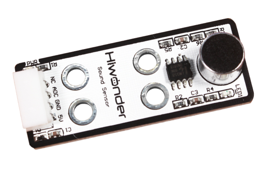
The path of the program file: “6. Secondary Development–Arduino Development–Sensor-extension Game–Program Files–Sound Detection and Placement–SoundSensor_put–SoundSensor_put.ino”
35 36 37 38 39 40 41 42 43 44 45 46 47 48 49 50 51 52 53 54 55 56 57 58 59 60 61 62 63 64 65 66 67 68 69 70 71 72 73 74 75 | while (true) { float soundValue = analogRead(sensor_pin); if (soundValue > 50) { if (num == 0 | (millis() - time_ms) < 1000) { time_ms = millis(); delay(80); num += 1; } Serial.println(soundValue); } if (num > 0 & (millis() - time_ms) > 1500) { if (num > 3) num = 3; num_st = true; Serial.println(num); } if (num_st) { setBuzzer(100); //Turn on buzzer for 100ms pos[0] = 0; pos[1] = -160; pos[2] = 100; set_position(pos, 1500); //Move above the color block delay(1500); pos[0] = 0; pos[1] = -160; pos[2] = 86; set_position(pos, 800); //Suction the color block Pump_on(); // Turn on the pump delay(1000); pos[0] = 0; pos[1] = -160; pos[2] = 180; set_position(pos, 1000); //Lift the robotic arm delay(1000); pos[0] = 120; pos[1] = (-20 - 60 * (num - 1)); pos[2] = 180; set_position(pos, 1500); // Move above the placement area delay(100); SetPWMServo(1, angle_pul[(num - 1)], 1000); // Angle compensation for proper placement |
This game uses a sound sensor to detect and identify the number of knocks, and then send the signal to the microcontroller for processing. When a knock is detected, the blue LED on sound sensor will flash, and the buzzer will sound, and then the robot arm will execute the corresponding action.
As shown in the figure below, the robot arm will pick up and place the object to the first position when knock on table once; when knock on table twice, the object will be placed to the second position; when knock on table third, the object will be placed to the third position.
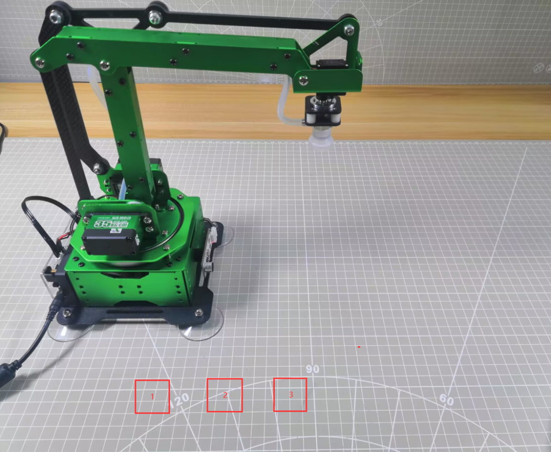
Then execute the functions for controlling action, buzzer, air pump to pick up and place object to the corresponding position in the left side (Take robotic arm as the first person view).
Note
If you knock on table over three times, object will be placed in the third position.
The interval between the knocks must be within 1s. If the interval is over 1.5s, program will re-calculate and execute the following process.
Due to the swing of the robot arm, the specific object landing point may be deviated, but the overall range will be as shown above.
(1) Preparation
① Hardware
Please assemble sound sensor to the corresponding position on MaxArm according to the tutorial in folder “Lesson 1 Sensor Assembly” under the same directory.
② Software
Please connect MaxArm to “Arduino IDE” according to the tutorial in folder “4. Underlying Program Learning–Arduino Development–Lesson 1 Set Development Environment”.
(2) Program Download
① Click on  icon to open “Arduino IDE”.

② Click “File”–“Open” in turn.
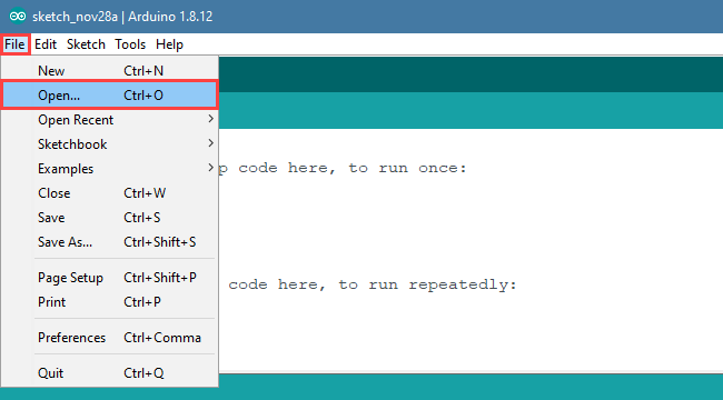
③ Open the program “SoundSensor_put.ino” in the folder “6.Secondary Development–Sensor-extension Game–Arduino Development–Program Files–Sound Detection and Placement–SoundSensor_put”.
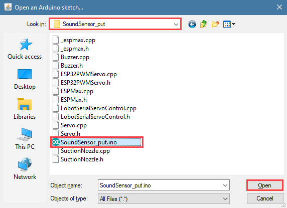
④ Select the model of development board. Click “Tools”–” Board” and select “ESP 32 Dev Module” (If the model of the development board has been configured when setting the development environment, you can skip this step).

⑤ Select the corresponding port of Arduino controller in “Tools”–“Port”. (Here take the port “COM5” as example. Please select the port based on your computer. If COM1 appears, please do not select because it is the system communication port but not the actual port of the development port.)

⑥ If you’re not sure about the port number, please open the “This PC” and click “Properties”–“Device Manger” in turns to check the corresponding port number (the device is with CH340). Then select the correct port on “Arduino IDE”.

⑦ After selecting, confirm the board “ESP32 Dev Module” in the lower right corner and the port number “COM5” (it is an example here, please refer to the actual situation).

⑧ Then click on  icon to verify the program. If no error, the status area will display “Compiling”–“Compile complete” in turn. After compiling, the information such as the current used bytes, and occupied program storage space will be displayed.

⑨ After compiling, click on  icon to upload the program to the development board. The status area will display “Compiling”–“Uploading”–“Complete” in turn. After uploading, the status area will stop printing the uploading information.

(3) Project Outcome
After the knock sound is detected, the blue LED light on sensor will flash corresponding to the number of knocks, then the robot arm rotates to the front and turns on the air pump to suck the block, moves and paces it to the position 1, 2, 3 of the placement area corresponding to the number of knocks. After that, turn off the air pump, reset and wait for the next command.
(4) Program Instruction
① Import function library and Initialize
The path of the program file: “6. Secondary Development–Sensor-extension Game–Arduino Development–Program Files–Sound Detection and Placement–SoundSensor_put\SoundSensor_put.ino”. If the program is modified, you can find a backup file in Appendix.
Before running the program, the buzzer, kinematics, kinematics encapsulation library, PWM servo, suction nozzle and other related library files need to be imported first.
1 2 3 4 5 6 | #include "Buzzer.h" #include "ESPMax.h" #include "_espmax.h" #include "ESP32PWMServo.h" #include "SuctionNozzle.h" #include "LobotSerialServoControl.h" |
Then, initialize the library file and robotic arm.
10 11 12 13 14 15 16 17 18 19 20 21 22 23 24 25 | #define sensor_pin 32 // Define sound sensor pin void setup() { // Initialize libraries Buzzer_init(); ESPMax_init(); Nozzle_init(); PWMServo_init(); analogReadResolution(10); analogSetClockDiv(ADC_11db); Serial.begin(115200); Serial.println("start..."); setBuzzer(100); // Turn on buzzer for 100ms go_home(2000); // Move robotic arm to home position SetPWMServo(1, 1500, 2000); // Set suction nozzle to initial position } |
② Sound Detection
Use analogRead() function to read the analog amount of detected knocks, and millis() function to read the sound interval time. if the analog amount reaches the set threshold and the knock interval is less than 1000ms, then the number of knocks plus one. If the number of detected knocks is greater than 3, then it will also be determined as only three knocks.
28 29 30 31 32 33 34 35 36 37 38 39 40 41 42 43 44 45 46 47 48 49 50 | void loop() { int num = 0; float pos[3]; bool num_st = false; long int time_ms = millis(); int angle_pul[3] = { 1800, 2000, 2200 }; while (true) { float soundValue = analogRead(sensor_pin); if (soundValue > 50) { if (num == 0 | (millis() - time_ms) < 1000) { time_ms = millis(); delay(80); num += 1; } Serial.println(soundValue); } if (num > 0 & (millis() - time_ms) > 1500) { if (num > 3) num = 3; num_st = true; Serial.println(num); } |
③ Sound Detection Feedback
When the knock sound is detected by sensor, the blue LED will flash corresponding times, and then MaxArm will execute the corresponding action.
When the sensor detects a knock, the blue LED will flash the corresponding number of times, and then MaxArm will perform the corresponding action.
52 53 54 55 56 57 58 59 60 61 62 63 64 65 66 67 68 69 70 71 72 73 74 | if (num_st) { setBuzzer(100); //Turn on buzzer for 100ms pos[0] = 0; pos[1] = -160; pos[2] = 100; set_position(pos, 1500); //Move above the color block delay(1500); pos[0] = 0; pos[1] = -160; pos[2] = 86; set_position(pos, 800); //Suction the color block Pump_on(); // Turn on the pump delay(1000); pos[0] = 0; pos[1] = -160; pos[2] = 180; set_position(pos, 1000); //Lift the robotic arm delay(1000); pos[0] = 120; pos[1] = (-20 - 60 * (num - 1)); pos[2] = 180; set_position(pos, 1500); // Move above the placement area delay(100); |
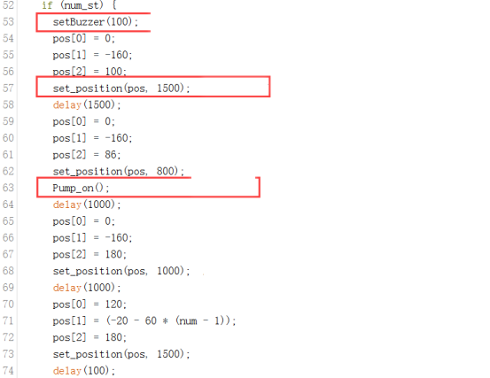
75 76 77 78 79 80 81 82 83 84 85 86 87 88 89 90 91 92 93 | SetPWMServo(1, angle_pul[(num - 1)], 1000); // Angle compensation for proper placement delay(500); pos[0] = 120; pos[1] = (-20 - 60 * (num - 1)); pos[2] = (88); set_position(pos, 1000); //Move to placement area delay(1200); Valve_on(); //Turn off pump and open solenoid valve pos[0] = 120; pos[1] = (-20 - 60 * (num - 1)); pos[2] = 200; set_position(pos, 1000); //Lift the robotic arm delay(1000); Valve_off(); //Turn off solenoid valve go_home(1500); // Return to home position delay(100); SetPWMServo(1, 1500, 1500); // Reset suction nozzle angle num_st = false; num = 0; |
Take setBuzze() function, set_position() function, Pump_on() function and go_home() for example.
The setBuzze() is a function to control buzzer. Call “Buzzer.h” function in the same directory as “InfraredSensor_sorting.ino” program. Fill in the parentheses with the duration time of buzzer, and the unit is ms. The code setBuzzer(100) means that the buzzer will respond for 100ms after the infrared sensor detects an object, and then the next set_potision() function will be executed.
53 | setBuzzer(100); //Turn on buzzer for 100ms |
The set_position() is a function to call robotic arm. Call “ESPMax.h” function in the same folder as “SoundSensor_put.ino” program. Fill in the parentheses with the coordinate values and duration time. Take the code set_position(pos,1500) for example, pos[0], pos[1], pos[2] is the representative of the robot arm corresponding to the position on the XYZ axis, 1500 is the running time, the unit is milliseconds (ms). After that, the Pump_on() function is executed in the next step.
54 55 56 57 | pos[0] = 0; pos[1] = -160; pos[2] = 100; set_position(pos, 1500); //Move above the color block |
The Pump_on() is a function to control air pump. Pump_on() function is to control the air pump on; Valve_on() function is used to turn off air pump and open solenoid valve; Valve_off() function to turn off the solenoid valve. Call “SoundSensor_put.ino” function in the same folder as the “SuctionNozzle.h” function, after the implementation of the next go_home() function.
63 | Pump_on(); // Turn on the pump |
82 | Valve_on(); //Turn off pump and open solenoid valve |
88 | Valve_off(); //Turn off solenoid valve |
The go_home() is a function to reset robotic arm. Cal “ESPMax.h” function in the same folder as “SoundSensor_put.ino” function.Fill in the parentheses with the action duration time, and the unit is ms. Take the code go_home(1500) for example. The parameter “1500” is the time it takes to complete the reset action. When this function is finished, the program will execute 1500ms delay function and then end this recognition and sorting actions and wait for the next recognition signal.
89 | go_home(1500); // Return to home position |
6.1.11 Light Detection and Placement
Please prepare a light-blocking prop for this game. You can use 3D printer to print a prop shown in the following image or use hard material to make one.
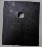
Project Principle
This game uses light sensor to sense the ambient light intensity to judge if it is covered by object. Then robot arm is controlled to place object in the corresponding area.
A photosensitive sensor is a sensitive device that responds or converts to external light signals or light radiation. The sensor mainly contains a QT523C (photodiode) and an LM358 chip (voltage comparator).
When it works, sensor uses QT523C to convert light signal to an electrical signal output, which is then converted to a voltage ranging 0 to 5V and received by the data collector after A/D conversion in the range of 0-1023. The greater the external brightness intensity, the smaller the output voltage, so the brightness is inversely proportional to the output voltage.
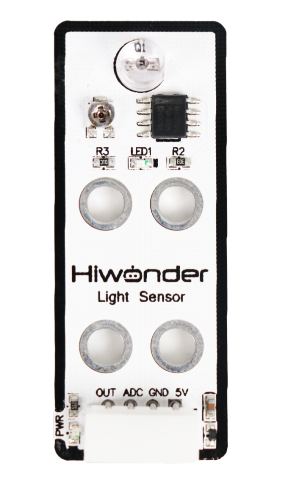
The path of the program file: “6. Secondary Development–Sensor-extension Game–Arduino Development–Program Files–Light Detection and Placement–LightSensor_put–LightSensor_put.ino “
33 34 35 36 37 38 39 40 41 42 43 44 45 46 47 48 49 50 51 52 53 54 55 56 57 58 59 60 61 62 63 | while (true) { float lightValue = analogRead(sensor_pin); // Read light sensor value, stronger light → smaller value Serial.println(lightValue); // Print sensor value via serial if (lightValue > 950) { // Sensor is blocked Serial.print("num: "); Serial.println(num + 1); setBuzzer(100); //Turn on buzzer for 100ms pos[0] = 0; pos[1] = -160; pos[2] = 100; set_position(pos, 1500); //Move above the color block delay(1500); pos[0] = 0; pos[1] = -160; pos[2] = 86; set_position(pos, 800); //Suction the color block Pump_on(); //Turn on the pump delay(1000); pos[0] = 0; pos[1] = -160; pos[2] = 180; set_position(pos, 1000); //Lift the robotic arm delay(1000); pos[0] = 120; pos[1] = (-20 - 60 * num); pos[2] = 180; set_position(pos, 1500); //Move above the placement area Serial.println(angle_pul[num]); delay(100); SetPWMServo(1, angle_pul[num], 1000); // Angle compensation for proper placement |
Use light sensor to detect the light intensity, and then send the signal to microcontroller for processing. When the light intensity is lower than the set threshold in program, buzzer will sound for responding, and MaxArm will perform the corresponding action.
The first detected object will be placed at position 1. The second detected object will be placed at position 2. The third detected object will be place at position 3. As the figure shown below:
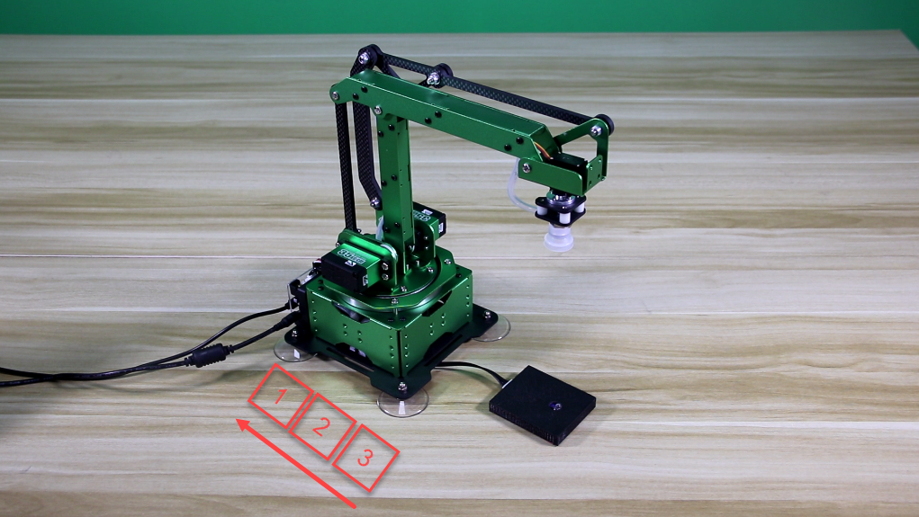
Then, execute the functions for controlling action, buzzer and air pump to control robot arm to move object and place it to the corresponding position on the left side. (Take robotic arm as the first person view)
Note
Since light sensor is susceptible to the ambient light, you may need to adjust the potentiometer of sensor based on the actual situation.
Due to the swing of the robot arm, the specific object landing point may be deviated, but the overall range will be as shown above.
When strong light is detected, the blue LED light on sensor will keep on. As the light becomes weak, the blue LED light will be off. Please note that this has nothing to do with the brightness of the sensor being covered by the object.
(1) Preparation
① Hardware
Please assemble light sensor to the corresponding position on MaxArm according to the tutorial in folder “Lesson 1 Sensor Assembly” in the same directory.
② Software
Please connect MaxArm to “Arduino IDE” according to the tutorial in folder “4. Underlying Program Learning–Arduino Development–Lesson 1 Set Development Environment”.
(2) Program Download
① Click on  icon to open “Arduino IDE”.

② Click “File”–“Open” in turn.

③ Open the program “LightSensor_put.ino” in the folder “6.Secondary Development–Sensor-extension Game–Arduino Development–Program Files–Light Detection and Placement–LightSensor_put”.
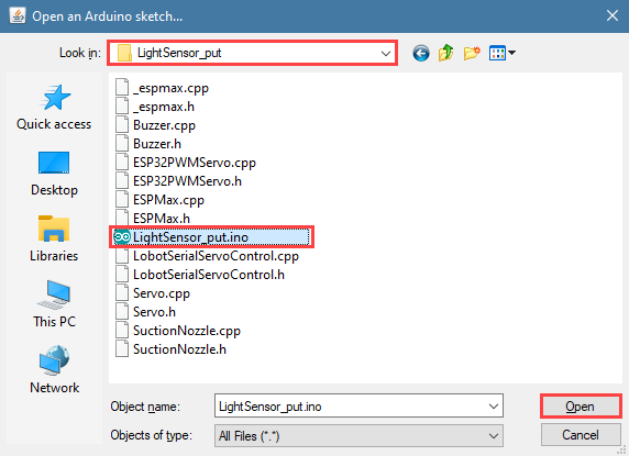
④ Select the model of development board. Click “Tools”–” Board” and select “ESP 32 Dev Module” (If the model of the development board has been configured when setting the development environment, you can skip this step).

⑤ Select the corresponding port of Arduino controller in “Tools”–“Port”. (Here take the port “COM5” as example. Please select the port based on your computer. If COM1 appears, please do not select because it is the system communication port but not the actual port of the development port.)

⑥ If you’re not sure about the port number, please open the “This PC” and click “Properties”–“Device Manger” in turns to check the corresponding port number (the device is with CH340). Then select the correct port on “Arduino IDE”.

⑦ After selecting, confirm the board “ESP32 Dev Module” in the lower right corner and the port number “COM5” (it is an example here, please refer to the actual situation).

⑧ Then click on  icon to verify the program. If no error, the status area will display “Compiling”–“Compile complete” in turn. After compiling, the information such as the current used bytes, and occupied program storage space will be displayed.

⑨ After compiling, click on  icon to upload the program to the development board. The status area will display “Compiling”–“Uploading”–“Complete” in turn. After uploading, the status area will stop printing the uploading information.

(3) Project Outcome
When light sensor starts to detecting light, it covered by object resulting in the light intensity is lower than the threshold set in program. At this time, microcontroller will receive a command, and then robot arm will turn on air pump and suck the object and place it to corresponding position. After that, turn off the air pump, reset and wait for the next command.
(4) Program Instruction
① Import function library and Initialize
The path of the program file: “6. Secondary Development–Sensor-extension Game–Arduino Development–Program Files–light Detection and Placement–LightSensor_put–LightSensor_put.ino”. If the program is modified, you can find the backup file in Appendix.
Before running the program, the buzzer, kinematics, kinematics encapsulation library, PWM servo, suction nozzle and other related library files need to be imported first.
1 2 3 4 5 6 | #include "Buzzer.h" #include "ESPMax.h" #include "_espmax.h" #include "ESP32PWMServo.h" #include "SuctionNozzle.h" #include "LobotSerialServoControl.h" |
Then, initialize the library files and robotic arm.
10 11 12 13 14 15 16 17 18 19 20 21 22 23 24 25 | #define sensor_pin 32 // Define light sensor pin void setup() { // Initialize libraries Buzzer_init(); ESPMax_init(); Nozzle_init(); PWMServo_init(); analogReadResolution(10); analogSetClockDiv(ADC_11db); Serial.begin(115200); Serial.println("start..."); setBuzzer(100); // Turn on buzzer for 100ms go_home(2000); // Move robotic arm to initial position SetPWMServo(1, 1500, 2000); // Set suction nozzle to initial position } |
② Light Detection
Use analogRead() function to read the analog amount of detected light intensity. When the analog amount reaches the set threshold, the program will place object at position 1. When the next object is detected, it will be placed at position 2. After recognizing and placing three time, game will enter the next round.
28 29 30 31 32 33 34 35 36 37 38 39 | void loop() { int num = 0; float pos[3]; int angle_pul[3] = { 1600, 1800, 2000 }; while (true) { float lightValue = analogRead(sensor_pin); // Read light sensor value, stronger light → smaller value Serial.println(lightValue); // Print sensor value via serial if (lightValue > 950) { // Sensor is blocked Serial.print("num: "); Serial.println(num + 1); |
81 82 83 84 85 86 | if (num >= 3) { num = 0; setBuzzer(100); //Turn on buzzer for 100ms delay(100); setBuzzer(100); //Turn on buzzer for 100ms } |
③ Light Detection Feedback
When cover is detected by sensor, MaxArm will execute the corresponding action.
37 38 39 40 41 42 43 44 45 46 47 48 49 50 51 52 53 54 55 56 57 58 59 60 61 62 63 64 65 66 67 68 69 70 71 72 73 74 75 76 77 78 79 | if (lightValue > 950) { // Sensor is blocked Serial.print("num: "); Serial.println(num + 1); setBuzzer(100); //Turn on buzzer for 100ms pos[0] = 0; pos[1] = -160; pos[2] = 100; set_position(pos, 1500); //Move above the color block delay(1500); pos[0] = 0; pos[1] = -160; pos[2] = 86; set_position(pos, 800); //Suction the color block Pump_on(); //Turn on the pump delay(1000); pos[0] = 0; pos[1] = -160; pos[2] = 180; set_position(pos, 1000); //Lift the robotic arm delay(1000); pos[0] = 120; pos[1] = (-20 - 60 * num); pos[2] = 180; set_position(pos, 1500); //Move above the placement area Serial.println(angle_pul[num]); delay(100); SetPWMServo(1, angle_pul[num], 1000); // Angle compensation for proper placement delay(500); pos[0] = 120; pos[1] = (-20 - 60 * num); pos[2] = 88; set_position(pos, 1000); //Move to placement area delay(1200); Valve_on(); //Turn off pump and open solenoid valve pos[0] = 120; pos[1] = (-20 - 60 * num); pos[2] = 200; set_position(pos, 1000); //Lift the robotic arm delay(1000); Valve_off(); //Turn off solenoid valve go_home(1500); //Return to home position delay(100); SetPWMServo(1, 1500, 1500); // Reset suction nozzle angle |
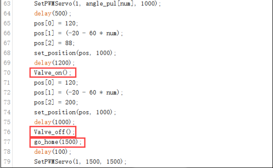
Take setBuzze() function, set_position() function, Pump_on() function and go_home() for example.
The setBuzze() is a function to control buzzer. Call “Buzzer.h” function in the same directory as “InfraredSensor_sorting.ino” program. Fill in the parentheses with the duration time of buzzer, and the unit is ms. The code setBuzzer(100) means that the buzzer will respond for 100ms after the infrared sensor detects an object, and then the next set_potision() function will be executed.
40 | setBuzzer(100); //Turn on buzzer for 100ms |
The set_position() is a function to call robotic arm. Call “ESPMax.h” function in the same folder as “LightSensor_put.ino” program. Fill in the parentheses with the coordinate values and duration time. Take the code set_position(pos,1500) for example, pos[0], pos[1], pos[2] is the representative of the robot arm corresponding to the position on the XYZ axis, 1500 is the running time, the unit is milliseconds (ms). After that, the Pump_on() function is executed in the next step.
41 42 43 44 | pos[0] = 0; pos[1] = -160; pos[2] = 100; set_position(pos, 1500); //Move above the color block |
The Pump_on() is a function to control air pump. Pump_on() function is to control the air pump on; Valve_on() function is used to turn off air pump and open solenoid valve; Valve_off() function to turn off the solenoid valve. Call “LightSensor_put.ino” function in the same folder as the “SuctionNozzle.h” function, after the implementation of the next go_home() function.
50 | Pump_on(); //Turn on the pump |
70 | Valve_on(); //Turn off pump and open solenoid valve |
76 | Valve_off(); //Turn off solenoid valve |
The go_home() is a function to reset robotic arm. Call “ESPMax.h” function in the same folder as “LightSensor_put.ino” function.Fill in the parentheses with the action duration time, and the unit is ms. Take the code go_home(1500) for example. The parameter “1500” is the time it takes to complete the reset action. When this function is finished, the program will execute 1500ms delay function and then end the game and wait for the next recognition signal.
77 | go_home(1500); //Return to home position |
(5) Adjust Sensitivity
There is an adjustable potentiometer knob on light sensor for adjusting the measuring distance. When performing the related games, if the measurement effect it not good enough, the measurement sensitivity of sensor can be adjusted by adjusting the knob.
It is recommended to use phillips screwdriver. Rotate the knob clockwise, as the figure shown below, to increase the measurement distance; rotate it counterclockwise to decrease the measurement distance.
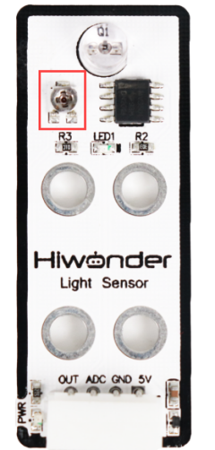
Please take notice of the following two tips:
① Since the warm light (incandescent light, sunlight, etc) contains more infrared component, there will be a certain interference the detection result. When using it, special attention should be paid to the surrounding environment. Therefore, you can not adjust the sensitivity alone.
② The sensitivity adjustment has is set a threshold, which you can regard it as a critical point. If the sensitivity exceeds the critical point, its value will return to the initial state.
③ Sensitivity adjustment needs to be based on the actual needs of the project. It is better to be adjusted to the most suitable conditions.
6.2 Python Development
6.2.1 What is the Inverse Kinematics
This lesson aims at helping users basically learning about the principle of inverse kinematics. The further learning and practical application of the inverse kinematics of robotic arm is available in the folder “7. Inverse Kinematics Lesson”
What is it?
Forward kinematics refers to process of obtaining position and velocity of end effector, given the known joint angles and angular velocities. In other word, the position information of end effector can be obtained when then joint angle and linkages parameters are known.
Inverse Kinematics is the inverse function or algorithm of Forward Kinematics. According to the position and post of the end effector along with linkages parameters, the joint position can be calculated, i.e., Given the robot’s end-effector positions, inverse kinematics can determine an appropriate joint configuration.
(1) Establish Coordinate System
A coordinate system must be established to describe the motion of an object. MaxArm uses x-y-z axes coordinate system (unit:mm) and takes the the base centre of robotic arm as original point (0,0,0), as the figure shown below.

The correspondence relationship between the movement orientation of end effector and the values of x-y-z axes is shown below (user per se as reference):
| Coordinate axis | control orientation |
|---|---|
| x | Control the end effector of robotic arm to move left or right (As the x value is positive, it moves to the right. As the x value is negative, it moves to the left. ) |
| y | Control the end effector of robotic arm to move forward and backward. (As the y value is negative,it moves backward. As the y value is positive, it moves forward.) |
| z | Control the end effector of robotic arm to move up and down (As the z value is negative, it moves up. As the z value is positive, it moves down.) |
(2) Project Operation
After learning about the principle and spatial concept of inverse kinematics, the control method of inverse kinematics can be mastered by a simple routine. You can follow the steps below to run the game.
① Install and connect Arduino. (Please refer to the tutorial in folder “4. Underlying Files Learning–Arduino Development–Lesson 1 Set Development Environment”)
② Double click to open “Arduino IDE”  .
.
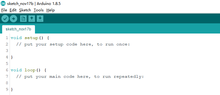
③ Click “File”–“Open”.

④ Select the program “kinematics_demo.ino” in the folder “5.MaxArm Hardware Basics Learning–Arduino Development–Game Programs–Program Files–kinematics_demo”, and click “Open”.
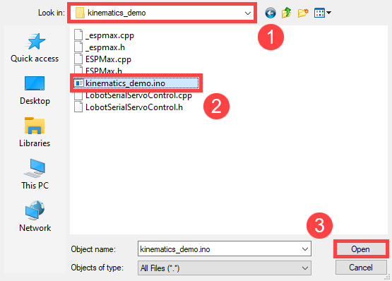
⑤ Check the board model. Click “Tools”–“Board” and select “ESP 32 Dev Module”. (If the model of development board has been configured when setting the development environment, you can skip this step.)

⑥ Select the corresponding port of ESP32 controller in “Tools”–“Port”. (Here take the port “COM5” as example. Please select the port based on your computer. If COM1 appears, please do not select because it is the system communication port but not the actual port of the development port.)

⑦ If you are not sure the port number, please open the “This PC” and click “Properties”–“Device Manger” in turns to check the corresponding port number (the device is with CH340).
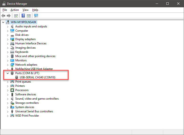
⑧ After selecting, confirm the board “ESP32 Dev Module” in the lower right corner and the port number “COM5” (it is an example here, please refer to the actual situation).

⑨ Then click on  icon to verify the program. If no error, the status area will display “Compiling”–“Compile complete” in turn. After compiling, the information such as the current used bytes, and occupied program storage space will be displayed.

⑩ After compiling, click on  icon to upload the program to the development board. The status area will display “Compiling”-“Uploading”-“Complete” in turn. After uploading, the status area will stop printing the uploading information.

(3) Project Analysis
The complete program is as follow:
1 2 3 4 5 6 7 8 9 10 11 12 13 14 15 16 17 18 19 20 21 22 23 24 25 26 27 28 29 30 31 32 33 34 35 36 37 38 39 40 41 42 43 44 | #include "ESPMax.h" #include "_espmax.h" // Inverse kinematics basic example void setup(){ ESPMax_init(); go_home(2000); // Move the robotic arm back to the initial position Serial.begin(9600); Serial.println("start..."); } bool start_en = true; void loop(){ if(start_en){ float x,y,z; float pos[3]; // XYZ position of the robotic arm’s initial pose x = 0; y = -(L1 + L3 + L4); z = (L0 + L2); // Print XYZ position via serial, unit: millimeter Serial.print(x); Serial.print("; "); Serial.print(y); Serial.print("; "); Serial.println(z); // Since the initial position of the robotic arm is already at the edge of its reachable workspace, it must first move downward along the Z-axis. Otherwise, the arm will not be able to // move along the X or Y axes. // set_position(pos,t), pos={x,y,z}; x: X-axis coordinate, y: Y-axis coordinate, z: Z-axis coordinate, t: total movement time (the longer the time, the slower the speed) pos[0] = x; pos[1] = y; pos[2] = z-100; set_position(pos,2000); // Move Z-axis 100mm down relative to the initial position delay(2000); pos[0] = x; pos[1] = y; pos[2] = z; set_position(pos,2000); // Reset robotic arm to initial pose delay(1000); start_en = false; } else{ delay(500); // Delay 500 ms } |
① Import function library
Before the robotic arm starts to move, the encapsulation library and underlying library of inverse kinematics need to be imported.
1 2 | #include "ESPMax.h" #include "_espmax.h" |
② Calculate the initial position of robotic arm
According to the linkage parameters of L0-L4 defined in kinematics underlying library.
1 2 3 4 5 6 7 8 | #ifndef _ESPMAX_H #define _ESPMAX_H #define L0 84.4 #define L1 8.14 #define L2 128.4 #define L3 138.0 #define L4 16.8 |
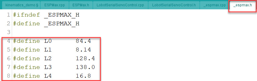
Calculate the initial position of the end effector. (Use the L0-L4 values to get x=0, y=162.94, z=212.8)
18 19 20 21 | // XYZ position of the robotic arm’s initial pose x = 0; y = -(L1 + L3 + L4); z = (L0 + L2); |
③ Control robotic arm
Use the function set_position() to control the end effector to move.
Take the code set_position(pos,2000) as example.
34 35 36 37 38 39 | pos[0] = x; pos[1] = y; pos[2] = z-100; set_position(pos,2000); // Move Z-axis 100mm down relative to the initial position delay(2000); pos[0] = x; pos[1] = y; pos[2] = z; set_position(pos,2000); // Reset robotic arm to initial pose delay(1000); |
The first parameter “pos” is a set of valuea representing the position values of the end effector on x-y-z axis.
Among them, pos[0] represents the x-axis value of the initial position of the end-effector.
pos[1] represents the the y-axis value of the initial position of the end-effector.
“pos[2]” represents the end-effector moves down to 100mm. And the position of the end effector can be set by modifying the x,y and z values.
For example, if want to control the end-effector to move 200mm to the left. (its position relative to the original moves to 200mm to the left), set x value plus 200. If want to move to 200 to the right, set x-200.
If want to directly move to the set position, for example, move to 200mm on x axis, you just need to set x=200.
The second parameter “2000” is the running time and the unit is ms.
(4) Inverse kinematics library analysis
The path to the inverse kinematics library: Appendix–8. Controller Underlying Files–Arduino Development–espmax.py
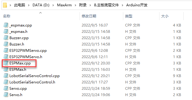
① Import head file and define pin
1 2 3 | #include "ESPMax.h" #include "_espmax.h" #include "LobotSerialServoControl.h" |
Import the inverse kinematics and servo head files.
5 6 7 8 9 10 | #define SERVO_SERIAL_RX 35 #define SERVO_SERIAL_TX 12 #define receiveEnablePin 13 #define transmitEnablePin 14 HardwareSerial HardwareSerial(2); LobotSerialServoControl BusServo(HardwareSerial,receiveEnablePin,transmitEnablePin); |
Define the serial communication pin.
② Initialization
12 13 14 15 16 17 18 | float ORIGIN[3] ={ 0, -(L1 + L3 + L4), (L0 + L2)}; float positions[3]; void ESPMax_init(){ BusServo.OnInit(); HardwareSerial.begin(115200,SERIAL_8N1,SERVO_SERIAL_RX,SERVO_SERIAL_TX); } |
ORIGIN[3] is the initial position of the end effector calculating from the linkage length.
The function ESPMax_init() is used for initialization
The function BusServo.OnInit() is the servo configuration initialization. HardwareSerial.begin() is serial communication configuration. “115200” is the baud rate. “SERIAL_8N1” refers to the working mode. SERVO_SERIAL_RX is the pin number of RX port. SERVO_SERIAL_TX is the pin number of TX port.
③ Control a single servo
20 21 22 23 24 25 | int set_servo_in_range(int servo_id, int p, int duration){ if(servo_id == 3 & p < 470) p = 470; if(servo_id == 2 & p > 700) p = 700; BusServo.LobotSerialServoMove(servo_id, p, duration); return int(1); } |
The function set_servo_in_range() is used to control the movement of a single servo, and limit the position of servo ID2 and ID3. The ID3 Servo can not be less than 470 impulse and the No.4 can not be less than 700. The parameter servo_id is servo ID number and the parameter “p” is servo impulse. The parameter “duration” is the running time.
The function BusServo.LobotSerialServoMove() in BusServo library controls a single servo to move.
④ Calculate servo pulse
27 28 29 30 31 32 | float* position_to_pulses(float pos[3], float* pul){ float angles[3]; inverse(pos,angles); deg_to_pulse(angles,pul); return pul; } |
The function position_to_pulses() is used to calculate the servo pulse. The parameter “position” is position coordinate. “angles” is servo angle. “pulse” is servo pulse. Then the value of servo pulse will be returned.
The function inverse() is used to calculate the servo angle according to the coordinates.
The function deg_to_pulse() is used to calculate the servo pulse according to the servo angle.
⑤ Calculate robotic arm position
34 35 36 37 38 39 | float* pulses_to_position(float pul[3], float* pos){ float joints[3]; pulse_to_deg(pul,joints); forward(joints,pos); return pos; } |
The function pulses_to_position() is used to calculate the coordinate of robotic arm position. The parameter pul[3] is servo pulse. The coordinate of robotic arm is calculated according to the servo pulses, and then the coordinate value is returned.
⑥ The movement of robotic arm
41 42 43 44 45 46 47 48 49 50 51 52 53 54 55 56 57 | int set_position(float pos[3], int duration){ float x = pos[0]; float y = pos[1]; float z = pos[2]; if(z > 255) z = 255; if(sqrt(x*x + y*y) < 50) return int(0); float angles[3]; inverse(pos,angles); float pul[3]; deg_to_pulse(angles,pul); for(int i=0; i<3; i++){ positions[i] = pul[i]; BusServo.LobotSerialServoMove(i+1,pul[i],duration); delay(2); } return int(1); } |
The function set_position() is used to control the robotic arm to move, and add the position limit. The parameter “position” is the position coordinate and the “duration” is the running time.
Use judgement statement to limit the robotic arm position. The coordinate of z-axis can not be greater than 225. The root of the sum of the squares of the x and y axes coordinates should be greater than 50, which means the end effector should be outside the circle with the coordinate origin as the center and the radius of 50. The unit is millimeter.
Then use “for” to control the ID1, ID2 and ID3 servos to rotate.
⑦ Back to the initial position
83 84 85 | void go_home(int duration){ set_position(ORIGIN, duration); } |
The function go_home() is used to get robotic arm back to the initial position. The parameter “duration” is the running time and the parameter self.set_position() is to control robotic arm to move. The parameter ORIGIN is the coordinate of the initial position set in program.
⑧ Read position coordinate
93 94 95 96 97 98 99 | float* read_position(float* pos){ float pul[3]; for(int i=0; i<3; i++){ pul[i] = BusServo.LobotSerialServoReadPosition(i+1); } pulses_to_position(pul,pos); } |
Use the function self.bus_servo.get_position() to get the pulse value of servo ID1, ID2, and ID3.
Get the x,y,z position coordinate by calculating the robotic arm position function pulses_to_position(). Then the x, y and z values are obtained.
6.2.2 Ultrasonic Detection and Digital Tube Display
Project Principle
In this lesson, ultrasonic sensor will be used to detect object and the detection result will be displayed on digital tube.
The used glowing ultrasonic ranging module integrates ultrasonic transmitting circuits, ultrasonic receiving circuits, digital processing circuits, etc. inside the ranging chip. The module adopts IIC communication interface, and can read the measured distance through IIC communication.

Ultrasonic sensors have two main components: the transmitter and the receiver.
The module will automatically send eight 40khz square waves and detect if there are signals are sent back. If there are signals back, output a high level. Then the duration time is time when the ultrasonic waves are sent and returns.
Measured distance(L) =(high level time* the speed of time(340M/S))/2.
The ultrasonic probes integrates two RGB lights, not only can adjust the light brightness, but also through the red (R), green (G), blue (B) three color channel changes and their superposition on each other to achieve colorful color changes.
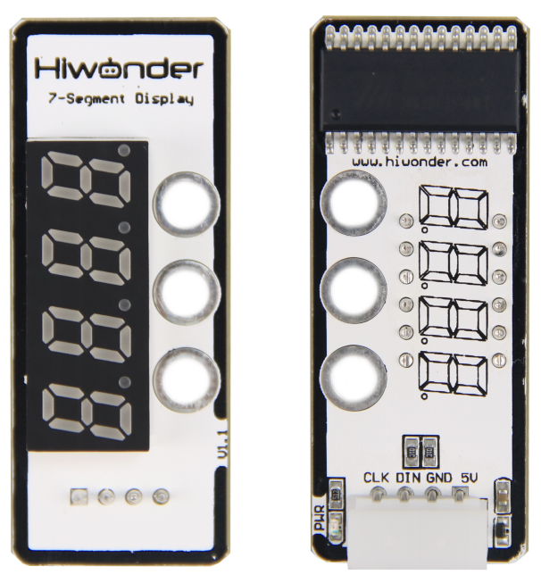
The digital tube has a 4-digit red LED for displaying numbers, decimal points and some special characters. This module is compact and easy to use, you can apply this module in robotics projects for displaying sensor values such as speed, time, fraction, temperature, distance, etc.
Firstly, import corresponding libraries and initialize ultrasonic sensor, buzzer, servo and digital tube module.
Then set the distance measurement conditions,three threshold intervals are set in program. Different intervals is distinguished with different colors.
(1) Preparation
① Hardware
Please assemble the ultrasonic sensor to the corresponding position on MaxArm according to the tutorial in folder “Lesson 1 Sensor Assembly” under the same directory.
② Software
Please connect MaxArm to Python editor according to the tutorial in folder “4. Underlying Program Learning–Python Development–Lesson 1 Set Development Environment”.
(2) Program Download
① After connecting, change the path of Workspace to “6. Secondary Development–Python Development–Sensor-extension Game”, and select “Program Files”.

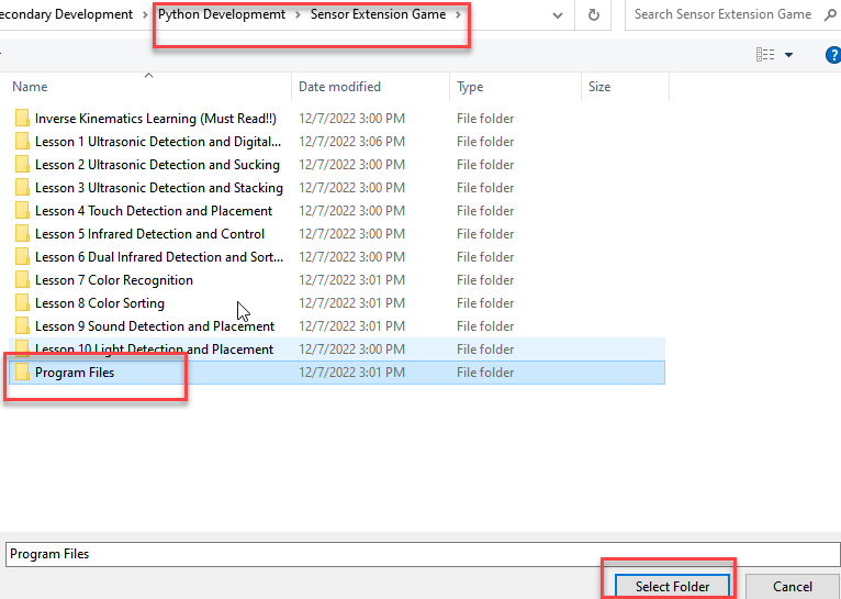
② Click the folder “Ultrasonic Detection and Digital Tube Display”, and then select all the program files in the folder.
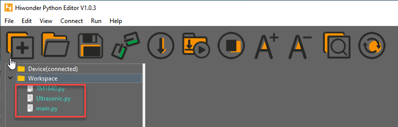
③ Then right click to download all the program files to the controller.
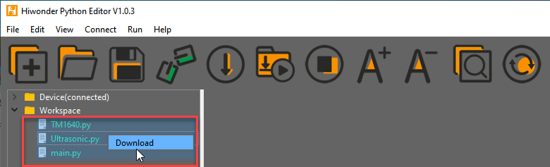
④ When the terminal prints the prompt as shown in the image below, it means download completed.
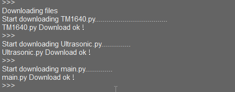
⑤ After downloading, click on the reset icon or press the reset button on ESP32 controller to run program.


(3) Project Outcome
Place a block or other objects in front of ultrasonic sensor, and then the corresponding distance will be displayed on digital tube. If the distance between sensor and object is less than 50cm, red light is on. If the distant is between 50cm and 100cm, green light is on. When the distance is farther than 100cm, blue light is on.
(4) Program Instruction
① Import library file
The path of program file: “../_static/source_code/Secondary_Development.zip”
Before the program is executed, I2C protocol, ultrasonic sensor, buzzer, PWM servo, bus servo, air pump and other related Python function libraries are imported.
1 2 3 4 5 6 7 8 9 10 | import time import TM1640 from machine import Pin, I2C from Buzzer import Buzzer from espmax import ESPMax from PWMServo import PWMServo from BusServo import BusServo from Ultrasonic import ULTRASONIC from RobotControl import RobotControl from SuctionNozzle import SuctionNozzle |
② Ultrasonic detection
The variables is set to read the distance measured by ultrasonic sensor.
36 37 38 | while True: Distance = hwsr06.getDistance() # Get the ultrasonic detection distance print("Distance =", Distance, "mm") # Print distance to the serial monitor |
③ LED Display
Display the distance value on digital tube.
39 | tm.tube_display_int(Distance) # Display distance on the digital tube |
④ Light Color Setting
If the distance between sensor and object is less than 50cm, green light is on.
If the distant is between 50cm and 100cm, red light is on.
When the distance is farther than 100cm, blue light is on.
40 41 42 43 44 45 46 | if Distance <= 50: # Distance ≤ 50mm hwsr06.setRGBValue(bytes([0,255,0, 0,255,0])) # Ultrasonic lights green elif 50 < Distance and Distance <= 100: # Distance > 50mm and ≤ 100mm hwsr06.setRGBValue(bytes([255,0,0, 255,0,0])) # Ultrasonic lights red elif 100 < Distance: # Distance > 100mm hwsr06.setRGBValue(bytes([0,0,255, 0,0,255])) # Ultrasonic lights blue time.sleep(0.2) # Delay 200ms |
6.2.3 Ultrasonic Detection and Suction
Working Principle
Ultrasonic sensors is a sensor that converts ultrasonic signals into other energy signals (usually electrical signals). There are two probes on ultrasonic sensor for receiving and transmitting ultrasound.
Firstly, import the corresponding library and initialize ultrasonic sensor, buzzer, servo and action groups.
Next, the object is detected by ultrasonic sensor and the measured distance is read by I2C protocol. After determining the distance, MaxArm will perform the corresponding action based on the determined result.
Then, execute the functions for controlling action group, starting buzzer and air pump to suck the object to the side.
The path to the program of the source code is “6. Secondary Development–Sensor-extension Game–Python Development–Program Files–Ultrasonic Detection and Suction–main.py”.
(1) Preparation
① Hardware
Please assemble the ultrasonic sensor to the corresponding position on MaxArm according to the tutorial in folder “Lesson 1 Sensor Assembly” under the same directory.
② Software
Please connect MaxArm to Python editor according to the tutorial in folder “4. Underlying Program Learning–Python Development–Lesson 1 Set Development Environment”.
(2) Program Download
After connecting, change the path of Workspace to “6. Secondary Development–Sensor-extension Game–Python Development–”, and select “Program Files”.


① Click the folder “Ultrasonic Detection and Suction”, and then select all the program files in the folder.
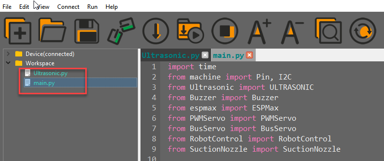
② Then right click to download all the program files to the controller.
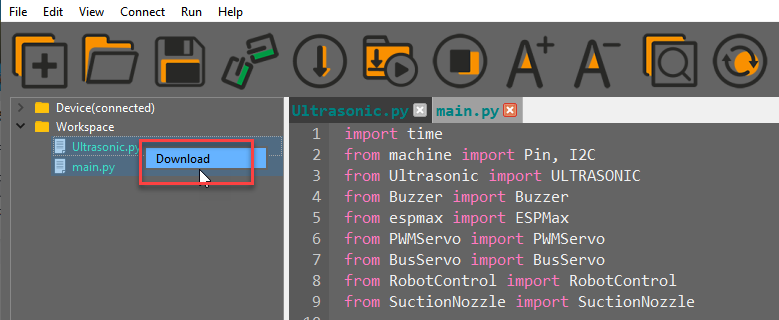
When the terminal prints the prompt as shown in the image below, it means download completed.

③ After downloading, click on the reset icon or press the reset button on ESP32 controller to run program.


(3) Project Outcome
After the object is detected by ultrasonic sensor, the buzzer will make “Di” sound, and the robotic arm will move to the object. Then suck and place the object to the right. After the air pump stops, MaxArm will return to the initial posture.
(4) Program Instruction
① Import library file
Before carrying out detection and suction, the I2C protocol, ultrasonic sensor, buzzer, PWM servo, bus servo, air pump and other related Python function libraries are imported.
The path to the program of the source code is “6. Secondary Development–Python Development–Sensor-extension Game–Sensor Programs–Ultrasonic Detection and Suction–mian.py”
1 2 3 4 5 6 7 8 9 | import time import TM1640 from machine import Pin, I2C from Buzzer import Buzzer from espmax import ESPMax from PWMServo import PWMServo from BusServo import BusServo from Ultrasonic import ULTRASONIC from RobotControl import RobotControl |
② Ultrasonic detection
The distance is measured by suing hwsr06.getDistance() function, and then use print() function to print out the measured distance.
38 | Distance = hwsr06.getDistance() # Get the ultrasonic detection distance |
③ Control robotic arm
Determine the distance of the front object first. If the object is between 60 and 80mm, MaxArm will perform the corresponding action.
40 41 42 43 44 45 46 47 48 49 50 51 52 53 54 55 56 57 58 59 60 61 62 | if 70 < Distance < 80: buzzer.setBuzzer(100) #Set buzzer on for 100ms arm.set_position((0,-160,100),1500) time.sleep_ms(1000) #Wait for 1000ms arm.set_position((0,-160,85),800) #Suction the color block nozzle.on() #Turn on the pump time.sleep_ms(1000) arm.set_position((0,-160,200),1000) #Lift up time.sleep_ms(1000) arm.set_position((70,-150,200),800) #Move above placement area nozzle.set_angle(30,600) time.sleep_ms(1000) nozzle.set_angle(35,300) arm.set_position((70,-150,90),800) #Move to placement area time.sleep_ms(800) arm.set_position((130,-150,88),500) #Move left slightly to place time.sleep_ms(500) nozzle.off() #Turn off suction pump arm.set_position((130,-150,200),1000) #Lift up time.sleep_ms(1000) arm.go_home() #Reset arm to initial position nozzle.set_angle(0,2000) time.sleep_ms(2000) |
Use the buzzer.setBuzze() function to control buzzer. Take the code buzzer.setBuzzer(100) as example:
The first parameter “(0,-160,100)” is the position of the suction nozzle on x, y and z axes.
The second parameter “1500” is the running time and the unit is ms.
Use the nozzle.set_angle() function to control the rotation of the suction nozzle. Take the code nozzle.set_angle(30,600) as example:
The first parameter “30” is the angle of PWM servo.
The second parameter “600” is the running time and the unit is ms.
6.2.4 Ultrasonic Detecting and Stacking
Working Principle
Ultrasonic sensor can convert ultrasonic signals into other energy signals (usually electrical signals). There are two probes on ultrasonic sensor for receiving and transmitting ultrasound.
Firstly, import the corresponding library and initialize ultrasonic sensor, buzzer, servo and action groups.
Next, the object is detected by ultrasonic sensor and the measured distance is read by I2C protocol. After determining the distance, MaxArm will perform the corresponding action based on the determined result.
Then, execute the functions for controlling action group, buzzer and air pump to suck the detected object to the side and stack it.
The path of the program file: “6. Secondary Development–Python Development–Sensor-extension Game–Program Files–Ultrasonic Detecting and stacking–main.py”.
1 2 3 4 5 6 7 8 9 | import time from machine import Pin, I2C from Ultrasonic import ULTRASONIC from Buzzer import Buzzer from espmax import ESPMax from PWMServo import PWMServo from BusServo import BusServo from RobotControl import RobotControl from SuctionNozzle import SuctionNozzle |
(1) Preparation
① Hardware
Please assemble the ultrasonic sensor to the corresponding position on MaxArm according to the tutorial in folder “Lesson 1 Sensor Assembly” under the same directory.
② Software
Please connect MaxArm to Python editor according to the tutorial in folder “4. Underlying Program Learning–Python Development–Lesson 1 Set Development Environment”.
(2) Program Download
① After connecting, change the path of Workspace to “6. Secondary Development–Python Development–Sensor-extension Game”, and select “Program Files”.


② Click the folder “Ultrasonic Detecting and Stacking”, and then select all the program files in the folder.
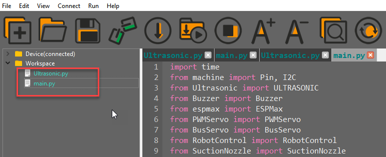
③ Then right click and select “Download” to download all the program files to the controller.
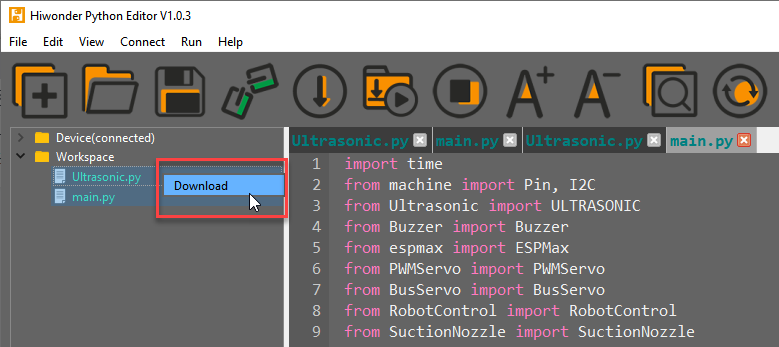
④ When the terminal prints the prompt as shown in the image below, it means download completed.
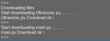
⑤ After downloading, click on the reset icon or press the reset button on ESP32 controller to run program.

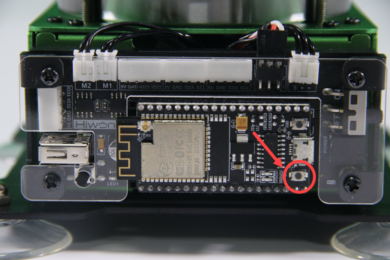
(3) Project Outcome
After putting the block on the fixed detection position, the buzzer will beep. Then MaxArm will suck the block to the left and stack it. The program will be repeated after stacking the three blocks.
(4) Program Instruction
① Import library file
The path of the program file: “6. Secondary Development–Python Development–Sensor-extension Game–Program Files–Ultrasonic Detecting and stacking–main.py”.
Before carrying out detection and suction, the Python function libraries related to I2C protocol, ultrasonic sensor, buzzer, PWM servo, bus servo, air pump and other related Python function libraries are imported.
1 2 3 4 5 6 7 8 9 | import time from machine import Pin, I2C from Ultrasonic import ULTRASONIC from Buzzer import Buzzer from espmax import ESPMax from PWMServo import PWMServo from BusServo import BusServo from RobotControl import RobotControl from SuctionNozzle import SuctionNozzle |
② Ultrasonic detection
Use the hwsr06.getDistance() function to measure distance. Then use print() function to print out the measured distance.
40 41 | Distance = hwsr06.getDistance() # Get ultrasonic detection distance print("distance = ", Distance) |
③ Control robotic arm
Determine whether there are objects at the distance between 70 and 80, and then perform the corresponding action.
42 43 44 45 46 47 48 49 50 51 52 53 54 55 56 57 58 59 60 | if 70 < Distance < 80: buzzer.setBuzzer(100) #Set buzzer to sound for 100ms time.sleep_ms(1000) #Wait 1000ms arm.set_position((0,-160,85),1500) #Suction the color block nozzle.on() #Turn on the pump time.sleep_ms(1600) arm.set_position((0,-160,200),1000) #Lift up time.sleep_ms(1000) arm.set_position((160,0,200),1500) #Move above placement area time.sleep_ms(1500) arm.set_position((160,0,(88+overlay*40)),1000) #Adjust placement height based on stacked count time.sleep_ms(1200) nozzle.off() #Turn off the pump arm.set_position((160,0,200),1000) #Lift up time.sleep_ms(1000) arm.go_home() #Reset arm to initial position time.sleep_ms(2000) overlay += 1 # Increase stacked count by 1 if overlay >= 3: overlay = 0 |
Use the buzzer.setBuzze() function to control the buzzer. Take the code buzzer.setBuzze() as example.
The first parameter “100” represents the sounding time of the buzzer and the unit is ms.
Use the arm.set_position() function to control robotic arm. Take the code arm.set_position((0,-160,85),1500) as example.
The first parameter “(0,-160,85)” is the position of the suction nozzle on x, y and z axes.
The second parameter “1500” represents the running time and the unit is ms.
6.2.5 Touch Detection and Placement
Working Principle
This lesson uses touch sensor based on the principle of capacitive sensing. After supplying the touch sensor power, the touching will be sensed when our fingers or metal touch the metal sensing plate. In the meantime, the signal terminal OUT will output low level signal, vice verse. According to this characteristics, the robotic arm can be controlled to perform the corresponding action.
The path of the program file is “6. Secondary Development–Python Development–Sensor-extension Game–Program Files–Touch Detection and Placement–main.py”.
1 2 3 4 5 6 7 8 9 10 11 12 13 14 15 16 17 18 | import time from Buzzer import Buzzer from espmax import ESPMax from PWMServo import PWMServo from BusServo import BusServo from Touch_sensor import TOUCH from RobotControl import RobotControl from SuctionNozzle import SuctionNozzle # Touch placement touch = TOUCH() pwm = PWMServo() buzzer = Buzzer() bus_servo = BusServo() arm = ESPMax(bus_servo) robot = RobotControl() nozzle = SuctionNozzle() |
Firstly, import the corresponding libraries and initialize buzzer, servo and action group.
Next, create the functions of buzzer and touch control. Set the buzzer to make sound feedback and the robotic arm to perform the corresponding action when short press the touch sensor.
Then, execute the function for controlling action, buzzer, and air pump to suck the detected object to the side and place it.
(1) Preparation
① Hardware
Please assemble the touch sensor to the corresponding position on MaxArm according to the tutorial in folder “Lesson 1 Sensor Assembly” under the same directory.
② Software
Please connect MaxArm to Python editor according to the tutorial in folder “4. Underlying Program Learning–Python Development–Lesson 1 Set Development Environment”
(2) Program Download
① After connecting, change the path of Workspace to “6. Secondary Development–Python Development–Sensor-extension Game”, and select “Program Files”.


② Click the folder “Touch Detection and Placement”, and then select all the program files in the folder.
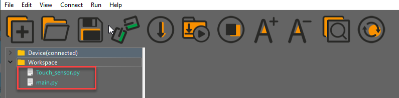
③ Then right click to download all the program files to the controller.
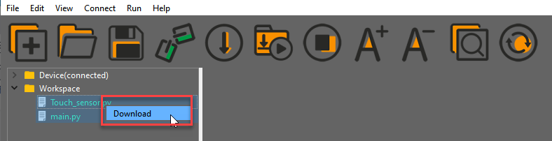
④ When the terminal prints the prompt as shown in the image below, it means download completed.
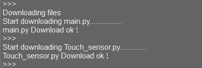
⑤ After downloading, click on the reset icon or press the reset button on ESP32 controller to run program.


(3) Project Outcome
After the buzzer beeps once, the robotic arm will suck and place the blocks in a line. When three blocks are placed completely, the buzzer will make “DiDi” sound as a feedback, and then a round of placement is finished.
(4) Program Instruction
① Import Function library
The path to the program of the source code is “6. Secondary Development Application–Python Development–Sensor Related Game–Game Programs–Touch Detection and Placement–main.py”.
Before executing the program, the buzzer, PWM servo, bus servo and air pump and other related Python function libraries need to be imported.
1 2 3 4 5 6 7 8 | import time from Buzzer import Buzzer from espmax import ESPMax from PWMServo import PWMServo from BusServo import BusServo from Touch_sensor import TOUCH from RobotControl import RobotControl from SuctionNozzle import SuctionNozzle |
② Touch detection
Use the touch.run_loop() function to detect whether the touch is sensed.
28 29 30 31 32 33 34 35 36 37 38 39 40 41 42 43 44 45 46 47 48 | if touch.down_up(): #Short press on touch sensor print('num:',num+1) buzzer.setBuzzer(100) #Buzzer beeps once arm.set_position((0,-160,100),1200) #Move arm above pickup position, wait 2s before suction time.sleep_ms(2000) arm.set_position((0,-160,85),600) #Suction the color block nozzle.on() # Turn on the pump time.sleep_ms(1000) arm.set_position((0,-160,180),1000) #Lift the arm time.sleep_ms(1000) arm.set_position((120,-20-60*num,180),1500) # Move above placement position nozzle.set_angle(angle[num],1500) #Apply angle compensation to align block time.sleep_ms(1500) arm.set_position((120,-20-60*num,83+num),1000) #Place the block time.sleep_ms(1200) nozzle.off() # Turn off pump arm.set_position((120,-20-60*num,200),1000) # Lift the arm time.sleep_ms(1000) arm.go_home() #Reset arm to initial position nozzle.set_angle(0,1800) #Reset suction nozzle angle to time.sleep_ms(2000) |
③ Control robotic arm
After sensing the touch, MaxArm will execute the corresponding action.
28 29 30 31 32 33 34 35 36 37 38 39 40 41 42 43 44 45 46 47 48 | if touch.down_up(): #Short press on touch sensor print('num:',num+1) buzzer.setBuzzer(100) #Buzzer beeps once arm.set_position((0,-160,100),1200) #Move arm above pickup position, wait 2s before suction time.sleep_ms(2000) arm.set_position((0,-160,85),600) #Suction the color block nozzle.on() # Turn on the pump time.sleep_ms(1000) arm.set_position((0,-160,180),1000) #Lift the arm time.sleep_ms(1000) arm.set_position((120,-20-60*num,180),1500) # Move above placement position nozzle.set_angle(angle[num],1500) #Apply angle compensation to align block time.sleep_ms(1500) arm.set_position((120,-20-60*num,83+num),1000) #Place the block time.sleep_ms(1200) nozzle.off() # Turn off pump arm.set_position((120,-20-60*num,200),1000) # Lift the arm time.sleep_ms(1000) arm.go_home() #Reset arm to initial position nozzle.set_angle(0,1800) #Reset suction nozzle angle to 0 time.sleep_ms(2000) |
Use the buzzer.setBuzze() function to control the buzzer. Take the code buzzer.setBuzzer(100) as example.
The first parameter “100” represents the sounding time and the unit is ms.
Use the arm.set_position() function to control the robotic arm. Take the code arm.set_position((0,-160,100),1200) as example.
The first parameter “(0,-160,100)” is the position of the suction nozzle on x, y and z axes.
The second parameter “1200” is the running time and the unit is ms.
Use the nozzle.set_angle() function to control the rotation of the suction nozzle. Take the code nozzle.set_angle(0,1800) as example.
The first parameter “0” represents the angle of PWM servo.
The second parameter “1800” represents the running time and the unit is ms.
6.2.6 Infrared Detection and Control
Working Principle
Infrared obstacle avoidance is a photoelectric sensor integrating IR transmitter and IR receiver. Featuring long detection distance and low interference from visible light , it is widely used in robot and assembly line piecework, etc.
This sensor detects obstacle by transmitting and receiving infrared. When the infrared transmitted by the sensor meets the obstacle ahead, the infrared will be reflected to the receiving terminal. When the sensor detects this signal, it will send it to the microcontroller for processing.
The closer the obstacle is, the stronger the reflection intensity; the farther the obstacle is, the weaker the reflection intensity. Different surface color has different reflection intensity. White is the strongest and black is the weakest.
The path of the program file: “6. Secondary Development–Python Development–Sensor-extension Game–Program Files–Infrared Detection and Control–main.py”.
1 2 3 4 5 6 7 8 9 10 11 12 13 14 15 16 17 18 | import time from Buzzer import Buzzer from espmax import ESPMax from PWMServo import PWMServo from BusServo import BusServo from Infrared_sensor import INFRARED from RobotControl import RobotControl from SuctionNozzle import SuctionNozzle #Infrared detection control pwm = PWMServo() buzzer = Buzzer() infrared = INFRARED() bus_servo = BusServo() arm = ESPMax(bus_servo) robot = RobotControl() nozzle = SuctionNozzle() |
Firstly, import the corresponding libraries and initialize buzzer, servo and action group.
Next, detect the object by the infrared sensor and buzzer will make sound. MaxArm will perform the corresponding action.
Then, execute the function for controlling action, buzzer, air pump to suck and place the object.
(1) Preparation
① Hardware
Please assemble the infrared sensor to the corresponding position on MaxArm according to the tutorial in folder “Lesson 1 Sensor Assembly” under the same directory.
② Software
Please connect MaxArm to Python editor according to the tutorial in folder “4. Underlying Program Learning–Python Development–Lesson 1 Set Development Environment”.
(2) Program Download
① After connecting, change the path of Workspace to “6. Secondary Development–Python Development–Sensor-extension Game”, and select “Program Files”.


② Click the folder “Infrared Detection and Control”, and then select all the program files in the folder.
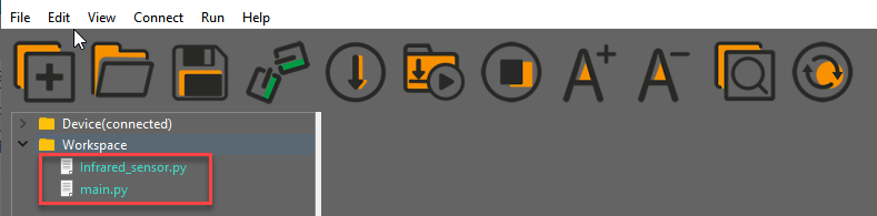
③ Then right click to download all the program files to the controller.
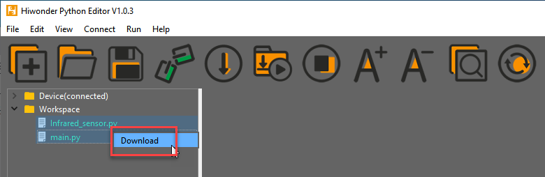
④ When the terminal prints the prompt as shown in the image below, it means download completed.
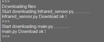
⑤ After downloading, click on the reset icon or press the reset button on ESP32 controller to run program.


(3) Project Outcome
After the buzzer make “Di” sound, MaxArm will suck and move the block to the placement area. Finally, the air pump will be turned off and MaxArm will return to the initial posture
(4) Program Instruction
① Import Function Library
The path of the program file: “6. Secondary Development–Python Development–Sensor-extension Game–Program Files–Infrared Detection and Control–main.py”.
Before executing the program, the buzzer, PWM servo, bus servo, infrared sensor, air pump and other related Python function libraries need to be imported.
1 2 3 4 5 6 7 8 | import time from Buzzer import Buzzer from espmax import ESPMax from PWMServo import PWMServo from BusServo import BusServo from Infrared_sensor import INFRARED from RobotControl import RobotControl from SuctionNozzle import SuctionNozzle |
② Infrared Detection
Use the infrared.run_loop() function to detect whether there is a object.
27 28 | while True: infrared.run_loop() |
③ Control robotic arm
After object is detected by the infrared sensor, MaxArm will execute the corresponding action.
30 31 32 33 34 35 36 37 38 39 40 41 42 43 44 45 46 47 | if infrared.close_long(): buzzer.setBuzzer(100) #Set buzzer on for 100 ms arm.set_position((0,-160,100),1500) time.sleep_ms(1000) #Wait for 1000 ms arm.set_position((0,-160,85),800) #Suction the color block nozzle.on() #Turn on the pump time.sleep_ms(1000) arm.set_position((0,-160,200),1000) #Lift up time.sleep_ms(1000) arm.set_position((70,-150,200),800) #Move above placing area nozzle.set_angle(30,600) time.sleep_ms(1000) nozzle.set_angle(35,300) arm.set_position((70,-150,90),800) #Move to placing area time.sleep_ms(800) arm.set_position((130,-150,88),500) #Shift left to place time.sleep_ms(500) nozzle.off() #Turn off vacuum pump |
Use the buzzer.setBuzze() function to control the buzzer. Take the code buzzer.setBuzzer(100) as example.
The first parameter “100” is the sounding time of buzzer and the unit is ms.
Use the arm.set_position() function to control the robotic arm. Take the code arm.set_position((0,-160,100),1500) as example.
The first parameter “(0,-160,100)” is the position of the suction nozzle on x, y and z axes.
The second parameter “1500” is the running time and the unit is ms.
Use the nozzle.set_angle() function to control the rotation of the suction nozzle. Take the code nozzle.set_angle(30,600) as example.
The first parameter “30” represents the angle of PWM servo.
The second parameter “600” represents the running time and the unit is ms.
6.2.7 Dual Infrared Detection and Sorting
Project Principle
Infrared obstacle avoidance is a photoelectric sensor integrating IR transmitter and IR receiver. Featuring long detection distance and low interference from visible light , it is widely used in robot and assembly line piecework, etc.
This sensor detects obstacle by transmitting and receiving infrared. When the infrared transmitted by the sensor meets the obstacle ahead, the infrared will be reflected to the receiving terminal. After the signal is detected, it will travel to microcontroller for processing.
The closer the obstacle is, the stronger the reflection intensity; the farther the obstacle is, the weaker the reflection intensity. Different surface color has different reflection intensity. White is the strongest and black is the weakest.
The path of program file: “6. Sensor-extension game–Python Development–Program Files–Dual Infrared Sorting–main.py”
1 2 3 4 5 6 7 8 9 10 11 12 13 14 15 16 17 18 19 20 21 22 23 24 25 26 27 28 29 30 31 32 33 34 35 36 37 38 39 40 41 | import time from Buzzer import Buzzer from espmax import ESPMax from PWMServo import PWMServo from BusServo import BusServo from Infrared_sensor import INFRARED from RobotControl import RobotControl from SuctionNozzle import SuctionNozzle #Dual infrared detection and sorting pwm = PWMServo() buzzer = Buzzer() bus_servo = BusServo() arm = ESPMax(bus_servo) robot = RobotControl() nozzle = SuctionNozzle() infrared_left = INFRARED(23) infrared_right = INFRARED(32) infrared_left.set_long_close_time(500) infrared_right.set_long_close_time(500) if __name__ == '__main__': arm.go_home() # Arm reset to home position nozzle.set_angle(0,1000) #Set nozzle angle to 0 time.sleep_ms(2000) time_ = time.time() while True: infrared_left.run_loop() # Run sensor detection function time.sleep(0.05) infrared_right.run_loop() if infrared_left.close_long(): # Left sensor detects block print("infrared_left") buzzer.setBuzzer(100) #Set buzzer on for 100 ms arm.set_position((70,-165,120),1500) time.sleep_ms(1000) # Wait for 1000 ms arm.set_position((70,-165,86),800) #Suction the color block nozzle.on() #Turn on the pump time.sleep_ms(1000) |
Firstly, import the required libraries and reset robotic arm and suction nozzle.
Then call infrared detection function to detect object. When a object is detected, buzzer will sound for responding and robotic arm will suck the object and move it to the corresponding position.
(1) Preparation
① Hardware
Please assemble infrared sensor to the corresponding position on MaxArm according to the tutorial in folder “Lesson 1 Sensor Assembly” under the same directory.
② Software
Please connect MaxArm to Python editor according to the tutorial in folder “4. Underlying Program Learning–Python Development–Lesson 1 Set Development Environment”.
(2) Program Download
After connecting, change the path of Workspace to “6. Secondary Development–Python Development–Sensor-extension Game”, and select “Program Files”.
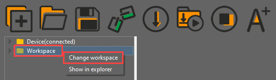

① Click the folder “Dual Infrared Detection and Sorting”, and then select all the program files in the folder.Then right click to download all the program files to the controller.
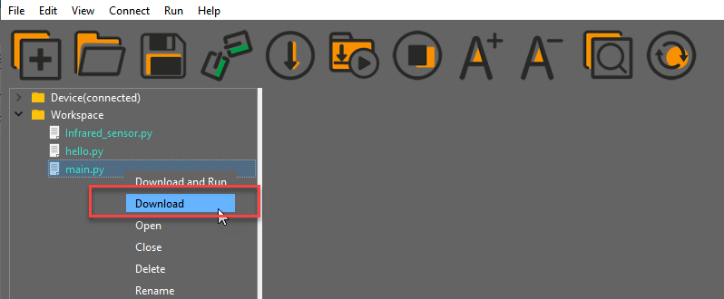

After downloading, click on the reset icon or press the reset button on ESP32 controller to run program.


(3) Project Outcome
Place a block in front of the right side of robot arm. When the block is detected by sensor, the buzzer will sound for a while and robotic arm will suck and place the block in the right side.
(4) Program Instruction
The path of program file: “6. Secondary Development–Python Development–Program Files–Dual Infrared Sorting–main.py”
① Initialization Configuration
Import function library
Firstly, import buzzer, kinematics, kinematics encapsulation library, PWM servo, suction nozzle and other related library files.
1 2 3 4 5 6 7 8 | import time from Buzzer import Buzzer from espmax import ESPMax from PWMServo import PWMServo from BusServo import BusServo from Infrared_sensor import INFRARED from RobotControl import RobotControl from SuctionNozzle import SuctionNozzle |
Reset
Call the related function to reset robotic arm and suction nozzle.
25 26 | arm.go_home() # Arm reset to home position nozzle.set_angle(0,1000) #Set nozzle angle to 0 |
The nozzle.set_angle() function is used to control the rotation angle of suction nozzle, that is, control the corresponding PWM servo. The meaning of parameters in parentheses are as follow:
The first parameter “0” refers to the rotation angle of PWM servo.
The second parameter “1000” is the running time, that is, the time for the servo to rotate the specified angle, and the unit is milliseconds (ms).
② Infrared Detection
Call infrared sensor to detect object. The infrared_left.run_loop() function is the detection function corresponding to the left sensor, and the infrared_right.run_loop() function is the detection function corresponding to the right sensor.
30 31 32 | infrared_left.run_loop() time.sleep(0.05) infrared_right.run_loop() |
③ Robotic Arm Control
Take the left infrared sensor for example to analyze its source code. The realization principle is the same with the right infrared sensor.
34 35 36 37 38 39 40 41 42 43 44 45 46 47 48 49 50 51 52 53 54 55 56 | if infrared_left.close_long(): # Left sensor detects block print("infrared_left") buzzer.setBuzzer(100) #Set buzzer on for 100 ms arm.set_position((70,-165,120),1500) time.sleep_ms(1000) # Wait for 1000 ms arm.set_position((70,-165,86),800) #Suction the color block nozzle.on() #Turn on the pump time.sleep_ms(1000) arm.set_position((70,-165,200),1000) #Lift up time.sleep_ms(1000) arm.set_position((150,-35,200),800) #Move above placing area nozzle.set_angle(15,500) time.sleep_ms(500) arm.set_position((150,-35,90),800) #Move to placing area time.sleep_ms(800) arm.set_position((150,10,88),500) #Shift to place time.sleep_ms(500) nozzle.off() #Turn off the pump arm.set_position((150,10,200),1000) #Lift up time.sleep_ms(1000) arm.go_home() #Arm reset to home position nozzle.set_angle(0,2000) time.sleep_ms(2000) |
Buzzer Feedback
When a block is detected by infrared sensor, the buzzer alarms by calling buzzer.setBuzzer() function. The parameter in parenthesis refers to the duration of alarming and the unit is ms.
36 | buzzer.setBuzzer(100) #Set buzzer on for 100 ms |
Suck & Place Block
By calling arm.set_position() function, robotic arm is controlled to rotate to the specific position. Combing this function and air pump control function to execute sorting function.
37 38 39 40 41 42 43 44 45 46 47 48 49 50 51 52 53 54 55 56 | arm.set_position((70,-165,120),1500) time.sleep_ms(1000) # Wait for 1000 ms arm.set_position((70,-165,86),800) #Suction the color block nozzle.on() #Turn on the pump time.sleep_ms(1000) arm.set_position((70,-165,200),1000) #Lift up time.sleep_ms(1000) arm.set_position((150,-35,200),800) #Move above placing area nozzle.set_angle(15,500) time.sleep_ms(500) arm.set_position((150,-35,90),800) #Move to placing area time.sleep_ms(800) arm.set_position((150,10,88),500) #Shift to place time.sleep_ms(500) nozzle.off() #Turn off the pump arm.set_position((150,10,200),1000) #Lift up time.sleep_ms(1000) arm.go_home() #Arm reset to home position nozzle.set_angle(0,2000) time.sleep_ms(2000) |
Take the code arm.set_position((70,-165,120),1500) for example. The meaning of the parameters in parenthesis is as follow:
The first parameter “(70,-165,120)” represents the target position, i.e., the target coordinate position of end effector. Three parameters are the value of x,y and z axes.
The second parameter “1500” is the running time, e.i., the time for the nozzle to move to the target position and the unit is ms.
6.2.8 Color Recognition
Working Principle
The color sensor is a sensor with various functions such as recognizing the color of objects, detecting the brightness of the surrounding environment, realizing object proximity detection and non-contact gesture detection, etc.
This lesson will use the color sensor for recognizing and comparing the RGB value of object. These sensors generally determine whether the detected color is consistent with the set one by using RGB (red, green, and blue) LED light sources and the ratio of R, G, and B wavelengths in the reflected light of an object.
The path of the program file: “6. Secondary Development–Sensor-extension Game–Python Development–Color Recognition–Program Files–Color Recognition–main.py”.
1 2 3 4 5 6 7 8 9 10 11 12 13 14 15 16 17 18 19 | import time from machine import Pin, I2C from Ultrasonic import ULTRASONIC from Color_sensor import COLOR from Buzzer import Buzzer from espmax import ESPMax from PWMServo import PWMServo from BusServo import BusServo from RobotControl import RobotControl from SuctionNozzle import SuctionNozzle # Color recognition pwm = PWMServo() buzzer = Buzzer() bus_servo = BusServo() arm = ESPMax(bus_servo) robot = RobotControl() nozzle = SuctionNozzle() |
Firstly, import the corresponding libraries and initialize ultrasonic sensor and color sensor.
Then read and calculate the RGB value of the object, and print out the color result.
Finally, the ultrasonic sensor emits light of the corresponding color.
(1) Preparation
① Hardware
Please assemble the color sensor and ultrasonic sensor to the corresponding position on MaxArm according to the tutorial in folder “Lesson 1 Sensor Assembly” under the same directory.
② Software
Please connect MaxArm to Python editor according to the tutorial in folder “4. Underlying Program Learning–Python Development–Lesson 1 Set Development Environment”.
(2) Program Download
① After connecting, change the path of Workspace to “6. Secondary Development–Sensor-extension Game–Python Development–”, and select “Program Files”.


② Click the folder “Color Recognition”, and then select all the program files in the folder.

③ Then right click to download all the program files to the controller.

When the terminal prints the prompt as shown in the image below, it means download completed.

④ After downloading, click on the reset icon or press the reset button on ESP32 controller to run program.


(3) Project Outcome
After the colored block is detected by the color sensor, the glowing ultrasonic sensor will emit the corresponding color light.
(4) Program Instruction
① Import Function Library
Before executing the program, the I2C protocol, ultrasonic sensor, color sensor, buzzer, PWM servo, bus servo, infrared sensor and air pump and other related Python function libraries need to be imported.
The path of the program file “6. Secondary Development–Python Development–Color Recognition–Program Files–Color Recognition–main.py”.
1 2 3 4 5 6 7 8 9 10 | import time from machine import Pin, I2C from Ultrasonic import ULTRASONIC from Color_sensor import COLOR from Buzzer import Buzzer from espmax import ESPMax from PWMServo import PWMServo from BusServo import BusServo from RobotControl import RobotControl from SuctionNozzle import SuctionNozzle |
② Color Detection
Use apds.readRedLight(), apds.readGreenLight() and apds.readBlueLight() functions to detect the value of RGB channel of object, and calculate.
51 52 53 54 55 56 57 58 | # Parse color sensor data c = apds.readAmbientLight() r = apds.readRedLight() g = apds.readGreenLight() b = apds.readBlueLight() r = int(255 * (r - r_f) / (R_F - r_f)) g = int(255 * (g - g_f) / (G_F - g_f)) b = int(255 * (b - b_f) / (B_F - b_f)) |
③ Control the LED of Ultrasonic Sensor
After calculating the value of RGB channel of object color, determine the color of the object.
59 60 61 | if r > 25 and r > g and r > b: # Output color detection result, set ultrasonic RGB accordingly color = RED # Detected red print('color: red') |
Then, the ultrasonic sensor will emit the corresponding light.
60 61 62 63 64 65 66 67 68 69 70 71 72 73 74 | color = RED # Detected red print('color: red') hwsr06.setRGBValue(bytes([255,0,0, 255,0,0])) elif g > 25 and g > r and g > b: color = GREEN # Detected green print('color: green') hwsr06.setRGBValue(bytes([0,255,0, 0,255,0])) elif b > 25 and b > g and b > r: color = BLUE # Detected blue print('color: blue') hwsr06.setRGBValue(bytes([0,0,255, 0,0,255])) else: # No color detected color = 0 print('') hwsr06.setRGBValue(bytes([255,255,255, 255,255,255])) |
Use hwsr06.setRGBValue(bytes()) function to control the LED of the ultrasonic sensor. Take the code hwsr06.setRGBValue(bytes([255,0,0, 255,0,0])) as example.
The first three parameters “255,0,0” are the color thresholds for the LED on the right side of the senor.
The last three parameters “255,0,0” are the color thresholds for the left LED of the sensor.
At this time, the LED emits red light.
6.2.9 Color Sorting
Working Principle
The color sensor is a sensor with various functions such as recognizing the color of objects, detecting the brightness of the surrounding environment, realizing object proximity detection and non-contact gesture detection, etc.
This lesson will use the color sensor for recognizing and comparing the RGB value of object. These sensors generally determine whether the detected color is consistent with the set one by using RGB (red, green, and blue) LED light sources and the ratio of R, G, and B wavelengths in the reflected light of an object.
The path of the program file: “6. Secondary Development–Python Development–Sensor-extension Game–Color Sorting–Program Files–Color Sorting–main.py”.
1 2 3 4 5 6 7 8 9 10 11 12 13 14 15 16 17 18 19 | import time from machine import Pin, I2C from Ultrasonic import ULTRASONIC from Color_sensor import COLOR from Buzzer import Buzzer from espmax import ESPMax from PWMServo import PWMServo from BusServo import BusServo from RobotControl import RobotControl from SuctionNozzle import SuctionNozzle # Color sorting pwm = PWMServo() buzzer = Buzzer() bus_servo = BusServo() arm = ESPMax(bus_servo) robot = RobotControl() nozzle = SuctionNozzle() |
Firstly, import the corresponding libraries and initialize ultrasonic sensor and color sensor.
Then read and calculate the RGB value of the object, and print out the color result.
Finally, the ultrasonic sensor emits corresponding light, and the functions for controlling servo and air pump are executed. MaxArm will suck and place the object to the corresponding position according to the color.
(1) Preparation
① Hardware
Please assemble the color sensor and the ultrasonic sensor to the corresponding position on MaxArm according to the tutorial in folder “Lesson 1 Sensor Assembly” under the same directory.
② Software
Please connect MaxArm to Python editor according to the tutorial in folder “4. Underlying Program–Python Development–Lesson 1 Set Development Environment”.
(2) Program Download
① After connecting, change the path of Workspace to “Appendix–7. Sensor-extension Game–Python Development” and select the folder “Program Files”.
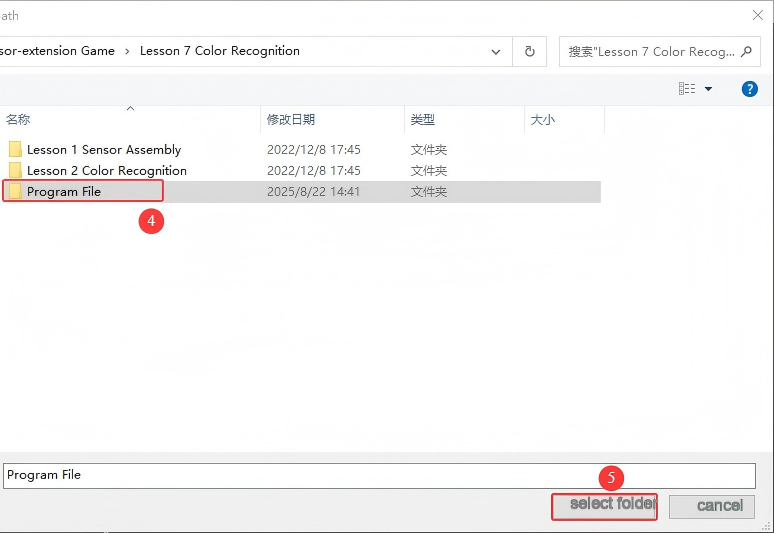
② Click the folder “Color Sorting”, and then select all the program files in the folder.
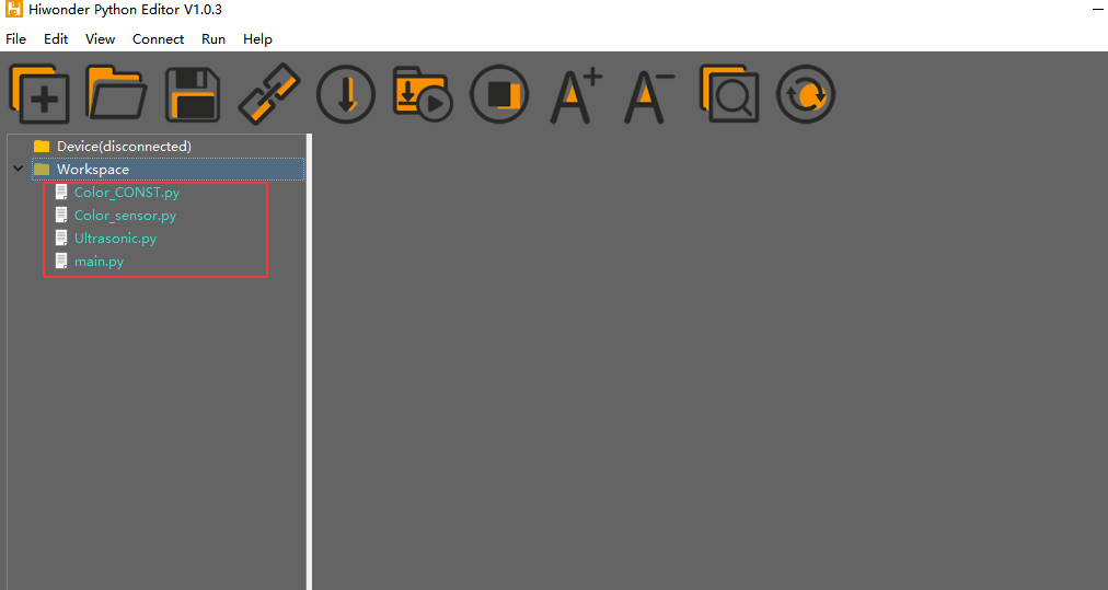
③ Then right click to download all the program files to the controller.
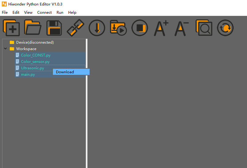
④ When the terminal prints the prompt as shown in the image below, it means download completed.
⑤ After downloading, click on the reset icon or press the reset button on ESP32 controller to run program.


(3) Project Outcome
After the color sensor recognizes the color of the block and the ultrasonic sensor detects that the block is placed in the placement area, MaxArm will sort the block based on the recognized color, and suck and transport the block to the corresponding position.
(4) Program Instruction
① Import function library
The path of the program file: “6. Secondary Development–Sensor-extension Game–Python Development–Color Sorting–Program Files–Color Sorting–main.py”.
Before executing the program, the I2C protocol, ultrasonic sensor, color sensor, buzzer, PWM servo, bus servo, infrared sensor, air pump and other related Python function libraries need to be imported.
1 2 3 4 5 6 7 8 9 10 | import time from machine import Pin, I2C from Ultrasonic import ULTRASONIC from Color_sensor import COLOR from Buzzer import Buzzer from espmax import ESPMax from PWMServo import PWMServo from BusServo import BusServo from RobotControl import RobotControl from SuctionNozzle import SuctionNozzle |
② Color Detection
Use apds.readRedLight(), apds.readGreenLight() and apds.readBlueLight() functions of color sensor to detect the value of RGB channel of object, and then calculate the value.
52 53 54 55 56 57 58 59 | # Parse color sensor data c = apds.readAmbientLight() r = apds.readRedLight() g = apds.readGreenLight() b = apds.readBlueLight() r = int(255 * (r - r_f) / (R_F - r_f)) g = int(255 * (g - g_f) / (G_F - g_f)) b = int(255 * (b - b_f) / (B_F - b_f)) |
③ Control the LED Light of Ultrasonic Sensor
After calculating the value of RGB channel of object color, determine the color of the object.
60 61 62 63 | if r > 25 and r > g and r > b:t = RED # Output color detection result elif g > 25 and g > r and g > b:t = GREEN elif b > 25 and b > g and b > r:t = BLUE else:t = 0 |
And the block with different color is set to place in the different position.
65 66 67 68 69 70 71 | if t > 0: buzzer.setBuzzer(100) color = t # Get the detected color print('color:',color) if color == 1: # Set ultrasonic RGB and placement coordinates based on color angle = -45 (x,y,z) = (120,-140,85) |
Then, the ultrasonic sensor emits the corresponding color light.
69 70 71 72 73 74 75 76 77 78 79 80 | if color == 1: # Set ultrasonic RGB and placement coordinates based on color angle = -45 (x,y,z) = (120,-140,85) hwsr06.setRGBValue(bytes([255,0,0, 255,0,0])) elif color == 2: angle = -25 (x,y,z) = (120,-80,85) hwsr06.setRGBValue(bytes([0,255,0, 0,255,0])) elif color == 3: angle = 0 (x,y,z) = (120,-20,82) hwsr06.setRGBValue(bytes([0,0,255, 0,0,255])) |
Use hwsr06.setRGBValue(bytes()) function to control the LED light of the ultrasonic sensor. Take the code hwsr06.setRGBValue(bytes([255,0,0, 255,0,0])) as example.
The first three parameters “255,0,0” are the color thresholds for the LED on the right side of the senor.
The last three parameters “255,0,0” are the color thresholds for the left LED of the sensor.
At this time, the LED emits red light.
④ Ultrasonic Detection
If the block is detected, use hwsr06.getDistance() function to measure distance. Then use print() function to print out the measured distance.
82 83 84 | if color > 0: # Color detected Distance = hwsr06.getDistance() # Get distance from ultrasonic sensor print('distance:', Distance) |
⑤ Control Robotic Arm
Determine whether there are objects at the distance between 70 and 80, and then execute the corresponding action.
85 86 87 88 89 90 91 92 93 94 95 96 97 98 99 100 101 | if 70 < Distance < 80: # Block distance satisfies picking condition, proceed to sorting buzzer.setBuzzer(100) #Buzz for 100ms time.sleep_ms(1000) arm.set_position((0,-160,85),1500) #Suction the color block nozzle.on() #Turn on the pump time.sleep_ms(1600) arm.set_position((0,-160,180),1000) #Lift arm time.sleep_ms(1000) arm.set_position((x,y,180),1000) #Move above corresponding placement area time.sleep_ms(1000) nozzle.set_angle(angle,800) # Set angle compensation arm.set_position((x,y,z),800) # Place block time.sleep_ms(1000) nozzle.off() #Turn off the pump arm.set_position((x,y,200),1000) #Lift arm time.sleep_ms(1000) arm.go_home() #Reset arm to home |
Use buzzer.setBuzze() function to control the buzzer. Take the code buzzer.setBuzze(100) as example.
The first parameter “100” represents the sounding time of buzzer and the unit is ms.
Use arm.set_position() function to control robotic arm. Take the code arm.set_position((0,-160,85),1500) as example.
The first parameter “(0,-160,85)” represents is the position of the suction nozzle on x, y and z axes.
The second parameter “1500” is the running time and the unit is ms.
Use nozzle.set_angle() function to control the rotation of the suction nozzle. Take the code nozzle.set_angle(0,800) as example.
The first parameter “0” is the angle of PWM servo.
The second parameter “800” is the running time and the unit is ms.
6.2.10 Sound Detection and Placement
Project Principle
Sound sensor has a in-built capacitive microphone. Sound waves cause the diaphragm in the microphone to vibrate, resulting in capacitance change, which in turn produces a correspondingly small change in voltage. This voltage is then converted into a voltage in the range of 0-5 V and compared with an adjustable voltage with adjusted sensitivity by means of a comparator.
Then it is received by the data collector through the A/D conversion of module, and the range is 0-1023. The value is higher as the sound intensity increases, so the detected sound is proportional to the output analog quantity.
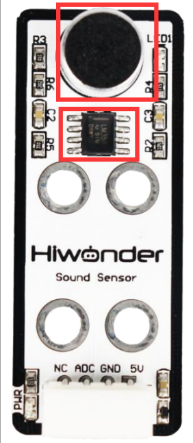
The path of program file: “6. Secondary Development–Sensor-extension Game–Python Development–Program Files–Light Detection and Placement–main.py”
19 20 21 22 23 24 25 26 27 28 29 30 31 32 33 34 35 36 37 38 39 | # Initialize light sensor light_sendor = ADC(Pin(32)) light_sendor.atten(ADC.ATTN_11DB) light_sendor.width(ADC.WIDTH_10BIT) if __name__ == '__main__': arm.go_home() #Reset arm to home position nozzle.set_angle(0,1000) #Set nozzle angle to 0 time.sleep_ms(2000) num = 0 #Block count variable angle = [12, 35, 55] #Angle compensation while True: light = light_sendor.read() #Read light sensor print(light) if light > 900: # Light sensor blocked print('num:',num+1) buzzer.setBuzzer(100) #Beep buzzer once time.sleep_ms(500) arm.set_position((0,-165,100),1200) #Move arm above pickup position and wait 2 seconds before picking up time.sleep_ms(2000) arm.set_position((0,-165,86),600) #Suction the color block |
Firstly, import sensor library files and initialize sensor.
Then create sound detection function to detect sound. After the sound is detected, buzzer will sound once for responding.
Then use kinematics to control robotic arm and place block to the corresponding position.
(1) Preparation
① Hardware
Please assemble sound sensor to the corresponding position on MaxArm according to the tutorial in folder “Lesson 1 Sensor Assembly” under the same directory.
② Software
Please connect MaxArm to Python editor according to the tutorial in folder “4. MaxArm Underlying Program Learning–Python Development–Lesson 1 Set Development Environment”.
(2) Program Download
① After connecting, change the path of Workspace to “6. Secondary Development–Python Development–Sensor-extension Game”, and select “Program Files”.
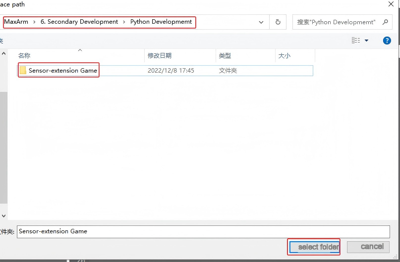
② Click the folder “Sound Detection and Placement”, and then select all the program files in the folder. Then right click to download all the program files to the controller.

When the terminal prints the prompt as shown in the image below, it means download completed.
③ After downloading, click on the reset icon or press the reset button on ESP32 controller to run program.


(3) Project Outcome
When a knock sound is detected by sensor, the buzzer will sound once. According to the number of knocks, robot arm will place object to the corresponding position in the right side (take robot arm as the first person view) . You can view the demo video for the specific effect.
(4) Program Instruction
① Import Function Library
The path of program file: “6. Secondary Development–Sensor-extension Game–Python Development–Program Files–Light Detection and Placement–main.py”
Before the program is executed, the related Python function libraries including buzzer, PWM servo, bus servo, air pump and other related Python function libraries are required to import.
1 2 3 4 5 6 7 8 | import time from machine import Pin,ADC from Buzzer import Buzzer from espmax import ESPMax from PWMServo import PWMServo from BusServo import BusServo from RobotControl import RobotControl from SuctionNozzle import SuctionNozzle |
② Initialization
Initialize sound sensor and robotic arm, which makes robotic arm back to the initial posture.
19 20 21 22 23 24 25 26 27 28 29 30 31 | # Initialize sound sensor sound_sendor = ADC(Pin(32)) sound_sendor.atten(ADC.ATTN_11DB) sound_sendor.width(ADC.WIDTH_10BIT) if __name__ == '__main__': arm.go_home() #Reset arm to home position nozzle.set_angle(0,1000) #Set nozzle angle to 0 time.sleep_ms(2000) angle = [12, 35, 55] #Angle compensation for placement time_ms = time.ticks_ms() num_st = False num = 0 |
③ Sound Detection
When the sound is detected, the number of knocks plus one. If the number of detected knocks is greater than 3, then game will start from a new round.
33 34 35 36 37 38 39 40 41 42 43 44 45 | while True: sound = sound_sendor.read() #Read sound sensor value if sound > 50: if num == 0 or (time.ticks_ms()-time_ms) < 1000: time_ms = time.ticks_ms() time.sleep_ms(80) num += 1 if num and (time.ticks_ms()-time_ms) > 1500: num = 3 if num > 3 else num num_st = True print(num) |
④ Control Robotic Arm
When sound is detected, robotic arm will suck up block and place it to the corresponding position according to the number of knocks.
47 48 49 50 51 52 53 54 55 56 57 58 59 60 61 62 63 64 65 66 67 68 | if num_st: buzzer.setBuzzer(100) # Buzz once arm.set_position((0,-160,100),1200) # Move arm above pickup position and wait 2 seconds before picking up time.sleep_ms(2000) arm.set_position((0,-160,86),600) # Suction the color block nozzle.on() # Turn on the pump time.sleep_ms(1000) arm.set_position((0,-160,180),1000) # Lift arm time.sleep_ms(1000) arm.set_position((120,-20-60*(num-1),180),1500) # Reset arm to home position nozzle.set_angle(angle[(num-1)],1500) # Set angle compensation time.sleep_ms(1500) arm.set_position((120,-20-60*(num-1),88),1000) # Place block time.sleep_ms(1200) nozzle.off() # Turn off the pump arm.set_position((120,-20-60*(num-1),200),1000) # Lift arm time.sleep_ms(1000) arm.go_home() # Reset arm to home position nozzle.set_angle(0,1800) # Reset nozzle angle to 0 time.sleep_ms(2000) num_st = False num = 0 |
The specific program for block placement control is as follow:
The program use the buzzer.setBuzze() function to control buzzer, as the figure shown below:
48 | buzzer.setBuzzer(100) # Buzz once |
Take the code buzzer.setBuzzer(100) for example:
The parameter “100” represent the sounding duration of buzzer and the unit is ms.
The use the arm.set_position() function to control robot arm to locate above the block, as the figure shown below:
49 50 | arm.set_position((0,-160,100),1200) # Move arm above pickup position and wait 2 seconds before picking up time.sleep_ms(2000) |
Take the code arm.set_position((0,-160,100),1200) for example:
The first parameter “(0,-160,100)” represents the coordinate of end effector. (You can read “Basic Kinematics Learning (must read!!!)” in folder “6. Secondary Development–6. Sensor-extension Game–Python Development”) to learn about space coordinate system.
The second parameter “1200” is the running time and the unit is ms.
Next, use the nozzle.on() function to turn on air pump. If it is nozzle.off() function, air pump will be off.
52 | nozzle.on() # Turn on the pump |
Then, use the nozzle.set_angle() function to control the rotation angle of suction nozzle, as the figure shown below:
56 | arm.set_position((120,-20-60*(num-1),180),1500) # Reset arm to home position |
Take the code arm.set_position((120,-20-60*(num-1),180),1500) for example.
The first parameter “120” represents the x-axis value of suction nozzle.
The second parameter -20-60*(num-1) represents the y-axis of suction nozzle. The value of y-axis is calculated according to the number of detected knocks.
The third parameter “1500” is the running time and the unit is ms.
After block moves to the corresponding position, use the nozzle.set_angle()function to adjust the angle of suction nozzle to place block in a neat direction.
57 58 | nozzle.set_angle(angle[(num-1)],1500) # Set angle compensation time.sleep_ms(1500) |
Take the code nozzle.set_angle(angle[(num-1)],1500) as example:
The first parameter “angle[(num-1)” is the angle setting. The different angles corresponding to three detection results are 12°, 35°and 55°individually, as the figure shown below:
28 | gle = [12, 35, 55] #Angle compensation for placement |
Finally, robotic arm will be place block to the corresponding position and turn off air pump. Robot arm will return to initial position and suction nozzle restore to the initial position.
59 60 61 62 63 64 65 | arm.set_position((120,-20-60*(num-1),88),1000) # Place block time.sleep_ms(1200) nozzle.off() # Turn off the pump arm.set_position((120,-20-60*(num-1),200),1000) # Lift arm time.sleep_ms(1000) arm.go_home() # Reset arm to home position nozzle.set_angle(0,1800) # Reset nozzle angle to 0 |
6.2.11 Light Detection and Placement
Please prepare a light-blocking prop for this game. You can use 3D printer to print a prop shown in the following image or use hard material to make one.

Project Principle
This game uses light sensor to sense the ambient light intensity to judge if it is covered by object. Then robot arm is controlled to place object in the corresponding area.
A photosensitive sensor is a sensitive device that responds or converts to external light signals or light radiation. The sensor mainly contains a QT523C (photodiode) and an LM358 chip (voltage comparator).
When it works, sensor uses QT523C to convert light signal to an electrical signal output, which is then converted to a voltage ranging 0 to 5V and received by the data collector after A/D conversion in the range of 0-1023. The greater the external brightness intensity, the smaller the output voltage, so the brightness is inversely proportional to the output voltage.

The path of the program file: “6. Secondary Devlopment–Sensor-extension Game–Python Development–Program Files–Sound Detection and Placement–main.py”
24 25 26 27 28 29 30 31 32 33 34 35 36 37 38 39 40 41 42 43 44 45 46 47 48 49 50 51 52 53 54 55 56 57 58 59 60 | if __name__ == '__main__': arm.go_home() #Reset arm to home position nozzle.set_angle(0,1000) #Set nozzle angle to 0 time.sleep_ms(2000) num = 0 #Block count variable angle = [12, 35, 55] #Angle compensation while True: light = light_sendor.read() #Read light sensor print(light) if light > 900: # Light sensor blocked print('num:',num+1) buzzer.setBuzzer(100) #Beep buzzer once time.sleep_ms(500) arm.set_position((0,-165,100),1200) #Move arm above pickup position and wait 2 seconds before picking up time.sleep_ms(2000) arm.set_position((0,-165,86),600) #Suction the color block nozzle.on() # Turn on the pump time.sleep_ms(1000) arm.set_position((0,-165,180),1000) #Lift arm time.sleep_ms(1000) arm.set_position((120,-20-60*num,180),1500) # Move above placement position nozzle.set_angle(angle[num],1500) #Set angle compensation to place block straight time.sleep_ms(1500) arm.set_position((120,-20-60*num,88),1000) #Place block time.sleep_ms(1200) nozzle.off() # Turn off the pump arm.set_position((120,-20-60*num,200),1000) # Lift arm time.sleep_ms(1000) arm.go_home() #Reset arm to home position nozzle.set_angle(0,1800) #Set nozzle angle to 0 time.sleep_ms(2000) num += 1 #Increment block count if num >= 3: num = 0 buzzer.setBuzzer(80) #Beep buzzer once time.sleep_ms(100) buzzer.setBuzzer(80) #Beep buzzer once |
Use light sensor to detect the light intensity, and then send the signal to microcontroller for processing. When the light intensity is lower than the set threshold in program, buzzer will sound for responding, and MaxArm will perform the corresponding action.
The first detected object will be placed at position 1. The second detected object will be placed at position 2. The third detected object will be place at position 3. As the figure shown below:

Then, execute the functions for controlling action, buzzer and air pump to control robot arm to move object and place it to the corresponding position on the left side. (Take robotic arm as the first person view)
Note
Since light sensor is susceptible to the ambient light, you may need to adjust the potentiometer of sensor based on the actual situation.
Due to the swing of the robot arm, the specific object landing point may be deviated, but the overall range will be as shown above.
When strong light is detected, the blue LED light on sensor will keep on. As the light becomes weak, the blue LED light will be off. Please note that this has nothing to do with the brightness of the sensor being covered by the object.
(1) Preparation
① Hardware
Please assemble sound sensor to the corresponding position on MaxArm according to the tutorial in folder “Lesson 1 Sensor Assembly” under the same directory.
② Software
Please connect MaxArm to Python editor according to the tutorial in folder “4. MaxArm Underlying Program Learning–Python Development–Lesson 1 Set Development Environment”.
(2) Program Download
① After connecting, change the path of Workspace to “6. Secondary Development–Python Development–Sensor-extension Game”, and select “Program Files”.

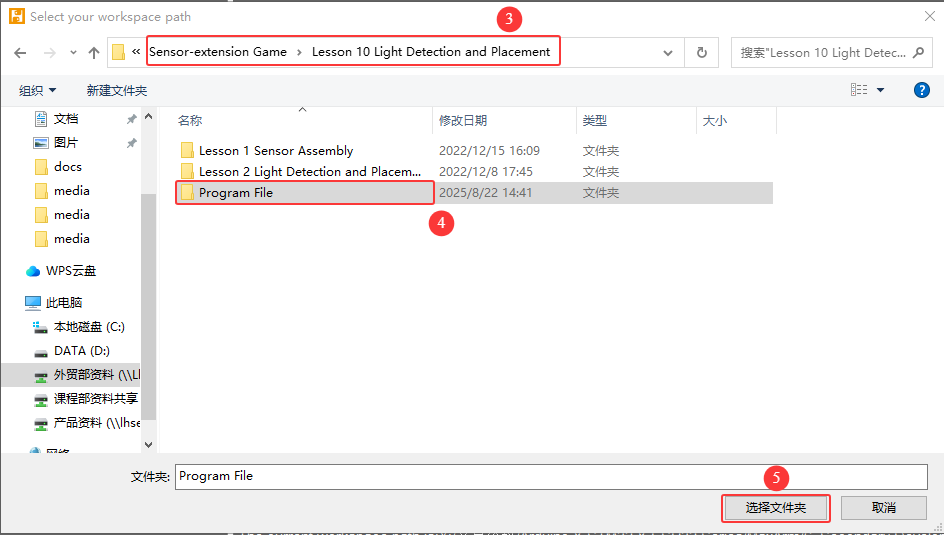
② Click the folder “Sound Detection and Placement” and select all the program files.
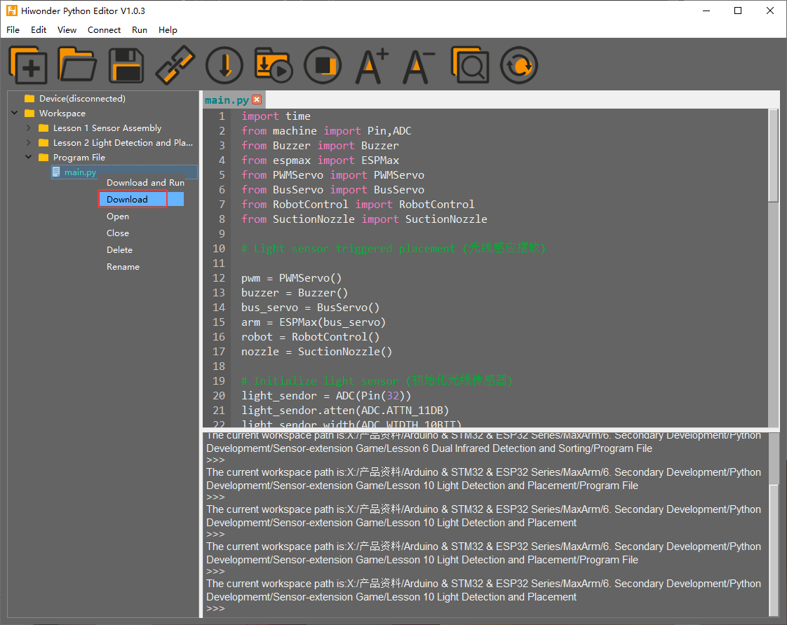
③ Then right click to download all the program files to the controller.

When the terminal prints the prompt as shown in the image below, it means download completed.
④ After downloading, click on the reset icon or press the reset button on ESP32 controller to run program.


(3) Project Outcome
When light sensor starts to detecting light, it covered by object resulting in the light intensity is lower than the threshold set in program. At this time, microcontroller will receive a command, and then robot arm will turn on air pump and suck the object and place it to corresponding position. After that, turn off the air pump, reset and wait for the next command.
(4) Program Instruction
① Import function library and Initialize
The path of the program file: “6. Secondary Development–Sensor-extension Game–Python Development–Program Files–light Detection and Placement–LightSensor_put–LightSensor_put.ino”. If the program is modified, you can find a backup file in Appendix.
Before running the program, the related function libraries including buzzer, PWM servo, bus servo, infrared sensor, and air pump are required to imported first.
1 2 3 4 5 6 7 8 | import time from machine import Pin,ADC from Buzzer import Buzzer from espmax import ESPMax from PWMServo import PWMServo from BusServo import BusServo from RobotControl import RobotControl from SuctionNozzle import SuctionNozzle |
Then, initialize the library files and robotic arm.
12 13 14 15 16 17 18 19 20 21 22 | pwm = PWMServo() buzzer = Buzzer() bus_servo = BusServo() arm = ESPMax(bus_servo) robot = RobotControl() nozzle = SuctionNozzle() # Initialize light sensor light_sendor = ADC(Pin(32)) light_sendor.atten(ADC.ATTN_11DB) light_sendor.width(ADC.WIDTH_10BIT) |
② Light Detection
Use analogRead() function to read the analog amount of detected light intensity. When the analog amount reaches the set threshold, the program will place object at position 1. When the next object is detected, it will be placed at position 2. After recognizing and placing three time, game will enter the next round.
24 25 26 27 28 29 30 31 32 33 34 35 36 37 38 39 40 41 42 43 44 45 46 47 48 49 50 51 52 53 54 55 56 57 58 59 60 | if __name__ == '__main__': arm.go_home() #Reset arm to home position nozzle.set_angle(0,1000) #Set nozzle angle to 0 time.sleep_ms(2000) num = 0 #Block count variable angle = [12, 35, 55] #Angle compensation while True: light = light_sendor.read() #Read light sensor print(light) if light > 900: # Light sensor blocked print('num:',num+1) buzzer.setBuzzer(100) #Beep buzzer once time.sleep_ms(500) arm.set_position((0,-165,100),1200) #Move arm above pickup position and wait 2 seconds before picking up time.sleep_ms(2000) arm.set_position((0,-165,86),600) #Suction the color block nozzle.on() # Turn on the pump time.sleep_ms(1000) arm.set_position((0,-165,180),1000) #Lift arm time.sleep_ms(1000) arm.set_position((120,-20-60*num,180),1500) # Move above placement position nozzle.set_angle(angle[num],1500) #Set angle compensation to place block straight time.sleep_ms(1500) arm.set_position((120,-20-60*num,88),1000) #Place block time.sleep_ms(1200) nozzle.off() # Turn off the pump arm.set_position((120,-20-60*num,200),1000) # Lift arm time.sleep_ms(1000) arm.go_home() #Reset arm to home position nozzle.set_angle(0,1800) #Set nozzle angle to 0 time.sleep_ms(2000) num += 1 #Increment block count if num >= 3: num = 0 buzzer.setBuzzer(80) #Beep buzzer once time.sleep_ms(100) buzzer.setBuzzer(80) #Beep buzzer once |
③ Light Detection Feedback
When cover is detected by sensor, MaxArm will execute the corresponding action.
24 25 26 27 28 29 30 31 32 33 34 35 36 37 38 39 40 41 42 43 44 45 46 47 48 49 50 51 52 53 54 55 | if __name__ == '__main__': arm.go_home() #Reset arm to home position nozzle.set_angle(0,1000) #Set nozzle angle to 0 time.sleep_ms(2000) num = 0 #Block count variable angle = [12, 35, 55] #Angle compensation while True: light = light_sendor.read() #Read light sensor print(light) if light > 900: # Light sensor blocked print('num:',num+1) buzzer.setBuzzer(100) #Beep buzzer once time.sleep_ms(500) arm.set_position((0,-165,100),1200) #Move arm above pickup position and wait 2 seconds before picking up time.sleep_ms(2000) arm.set_position((0,-165,86),600) #Suction the color block nozzle.on() # Turn on the pump time.sleep_ms(1000) arm.set_position((0,-165,180),1000) #Lift arm time.sleep_ms(1000) arm.set_position((120,-20-60*num,180),1500) # Move above placement position nozzle.set_angle(angle[num],1500) #Set angle compensation to place block straight time.sleep_ms(1500) arm.set_position((120,-20-60*num,88),1000) #Place block time.sleep_ms(1200) nozzle.off() # Turn off the pump arm.set_position((120,-20-60*num,200),1000) # Lift arm time.sleep_ms(1000) arm.go_home() #Reset arm to home position nozzle.set_angle(0,1800) #Set nozzle angle to 0 time.sleep_ms(2000) num += 1 #Increment block count |
Take setBuzze() function, set_position() function, Pump_on() function and go_home() for example.
The setBuzze() is a function to control buzzer. Call “Buzzer.h” function in the same directory as “InfraredSensor_sorting.ino” program. Fill in the parentheses with the duration time of buzzer, and the unit is ms. The code setBuzzer(100) means that the buzzer will respond for 100ms after the infrared sensor detects an object, and then the next set_potision() function will be executed.
35 | buzzer.setBuzzer(100) #Beep buzzer once |
The set_position() is a function to call robotic arm. Call “ESPMax.h” function in the same folder as “LightSensor_put.ino” program. Fill in the parentheses with the coordinate values and duration time. Take the code set_position(pos,1500) for example, pos[0], pos[1], pos[2] is the representative of the robot arm corresponding to the position on the XYZ axis, 1500 is the running time, the unit is milliseconds (ms). After that, the Pump_on() function is executed in the next step.
{lineno-start=}
arm.set_position((0,-165,100),1200) #Move arm above pickup position and wait 2 seconds before picking up
The nozzle.on() function is used to turn on air pump while the nozzle.off() function to turn off air pump. Then proceed to execute arm.go_home() function.
40 | nozzle.on() # Turn on the pump |
49 | nozzle.off() # Turn off the pump |
52 | arm.go_home() #Reset arm to home position |
The go_home() is a function to reset robotic arm. After turning off air pump, this function will be executed to get robot arm back to initial position. After that, the program will execute a function for 2000ms delay and then end the game and wait for the next recognition signal.
(5) Adjust Sensitivity
There is an adjustable potentiometer knob on light sensor for adjusting the measuring distance. When performing the related games, if the measurement effect it not good enough, the measurement sensitivity of sensor can be adjusted by adjusting the knob.
It is recommended to use phillips screwdriver. Rotate the knob clockwise, as the figure shown below, to increase the measurement distance; rotate it counterclockwise to decrease the measurement distance.

Please take notice of the following two tips:
① Since the warm light (incandescent light, sunlight, etc) contains more infrared component, there will be a certain interference the detection result. When using it, special attention should be paid to the surrounding environment. Therefore, you can not adjust the sensitivity alone.
② The sensitivity adjustment has is set a threshold, which you can regard it as a critical point. If the sensitivity exceeds the critical point, its value will return to the initial state.
③ Sensitivity adjustment needs to be based on the actual needs of the project. It is better to be adjusted to the most suitable conditions.