2. Arduino Development
2.1 Getting Started
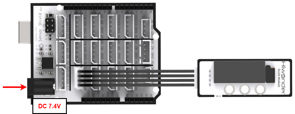
2.1.1 Wiring Instruction
This section illustrates connecting a 4-pin cable to the SDA and SCL ports on the Arduino expansion board. Refer to the diagram below.
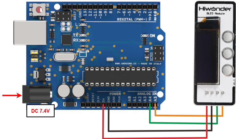
If you do not have an Arduino expansion board, use a Dupont wire to directly connect to the Arduino development board, just as below:
Note
When using Hiwonder’s lithium battery, connect the battery cable with the red wire to the positive (+) terminal and the black wire to the negative (–) terminal of the DC port.
If the battery is not connected to the cables, do not connect the cable ends directly together. Doing so may cause a short circuit and damage the system.
Before powering on, ensure that no metal objects are touching the controller. Otherwise, the exposed pins at the bottom of the board may cause a short circuit and damage the controller.
2.1.2 Environment Configuration
You can install the Arduino IDE on your computer. Download path: “Appendix-> Arduino Installation Package” For detailed usage of the Arduino IDE, please refer to the documentation in the same directory.
2.2 Test Case
Program to display “Hiwonder” and “1234” on the OLED sensor’s screen.
2.2.1 Program Download
Connect the Arduino UNO development board with the expansion board to the computer via a USB cable. You can open the Arduino IDE, click “File->New”, and import the code in the same directory as this tutorial.
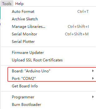
Remember to select the correct development board and port. The ports shown below are for reference only. Then compile and upload the program.
After the code is uploaded, click
 to open the serial monitor, set the baud rate to 9600 to observe the output.
2.2.2 Project Outcome
Two lines of characters are displayed on the OLED sensor: “Hiwonder” and “1234”.
2.2.3 Program Brief Analysis
Import Libraries
#include <U8g2lib.h>
Import the U8g2lib library, which is used for the OLED display. You can add it by searching for U8g2lib.h under “Project → Include Library → Manage Libraries” in the Arduino IDE interface.
Serial Port Initialization
U8G2_SSD1306_128X64_NONAME_1_HW_I2C u8g2(U8G2_R0, /* reset=*/ U8X8_PIN_NONE); //Instantiate object

void setup() {
  u8g2.begin(); //Initialize the library
  /*****************************************/
  //Set the display rotation to 180°
  //(U8G2_R0: no rotation, U8G2_R1: 90° rotation, U8G2_R2: 180° rotation, U8G2_R3: 270° rotation)
  /*******************************************/
  u8g2.setDisplayRotation(U8G2_R2);

}
First, instantiate a display object for the SSD1306 chip. Then, in the setup function, initialize the u8g2 class and set the display rotation to 180 degrees.
Loop Process
void loop()
{
  u8g2.firstPage(); //Create a canvas to send to the OLED sensor for display.
  do {
    u8g2.setFont(u8g2_font_fur20_tf); //Set the font
    u8g2.drawStr(0,20,"Hiwonder");    //Set the displayed content
    u8g2.setFont(u8g2_font_courB18_tf);
    u8g2.setCursor(0,50); //Switch the cursor position: Newly added characters will be displayed starting from the updated cursor location.
    u8g2.println(1234);   //Set display content from the new cursor position.
  }
  while ( u8g2.nextPage() );
}
In the loop() function, create a canvas and set the font. Then display the string “Hiwonder,” and finally set the cursor at position (0, 50) to display the string “1234.”