3. Raspberry Pi Development Tutorial
3.1 Getting Started
3.1.1 Wiring Instruction
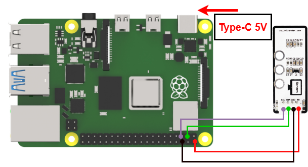
This section provides an example of connecting the OLED module with Dupont wires. Connect the module to the following pins: 5V, GND, SDA (GPIO24), and SCL (GPIO22). The wiring method is illustrated in the figure below.
Note
When using Hiwonder’s lithium battery, connect the battery cable with the red wire to the positive (+) terminal and the black wire to the negative (–) terminal of the DC port.
If the battery is not connected to the cables, do not connect the cable ends directly together. Doing so may cause a short circuit and damage the system.
Before powering on, ensure that no metal objects are touching the controller. Otherwise, the exposed pins at the bottom of the board may cause a short circuit and damage the controller.
3.1.2 Environment Configuration
Install NoMachine on your computer. The software package is located under “Appendix-> Remote Desktop Connection Tool”. For the detailed operations of NoMachine, please refer to the same directory.
Drag the program and SDK library files into the Raspberry Pi system image. For demonstration purposes, the files are placed on the Desktop in this example.
Note
Make sure the library files are placed in the same directory as the program.
Open the terminal and enter the command to grant read and write permissions to the folder:
sudo chmod a+x Sensor_Demo/
3.2 Test Case
Program to display the readings from the light sensor in the Raspberry Pi terminal window and control the module using a set threshold.
3.2.1 Program Download
Open the terminal and enter the command to navigate to the program directory, enter: cd Desktop/Sensor_Demo/, then press Enter.
cd Desktop/Sensor_Demo/
Run the program by entering:
python3 OledSensorDemo.py
3.2.2 Project Outcome
The text “1234” is displayed on the OLED display.
3.2.3 Program Brief Analysis
Import Libraries
from luma.core.interface.serial import i2c, spi
from luma.core.render import canvas
from luma.oled.device import ssd1306, ssd1325, ssd1331, sh1106
Import the library files required by the program.
Initialization Sequence
serial = i2c(port=1, address=0x3C)
device = ssd1306(serial, width=128,height=32)
Initialize the serial communication object, setting it to I2C communication and address 0x3C. Configure the display object device, using the SSD1306 class module, with a length of 128 pixels and a width of 32 pixels. Be sure to set the length and width, otherwise the displayed content will be incomplete.
Main Program
while(1):
    with canvas(device) as draw:
        draw.text((1, 1), "1234", fill="white") # Display "Hello World" at column 30, row 10 in white (将Hello World显示在屏幕第30列、第10行,显示的内容颜色为white(白色))
# Note: This screen cannot show white; it will display the current LED color instead (但该屏幕无法呈现白色,只能显示当前LED灯的颜色)
In the while loop, set the configured device object as the canvas. Starting at position (1,1) on the canvas, display the number “1234” in white font.
After the program successfully runs, you will see the text “1234” displayed on the OLED screen.