7. ROS+Machine Learning Course
7.1 MediaPipe Human-Robot Interaction
7.1.1 MediaPipe Introduction and Getting Started
7.1.1.1 Overview of MediaPipe
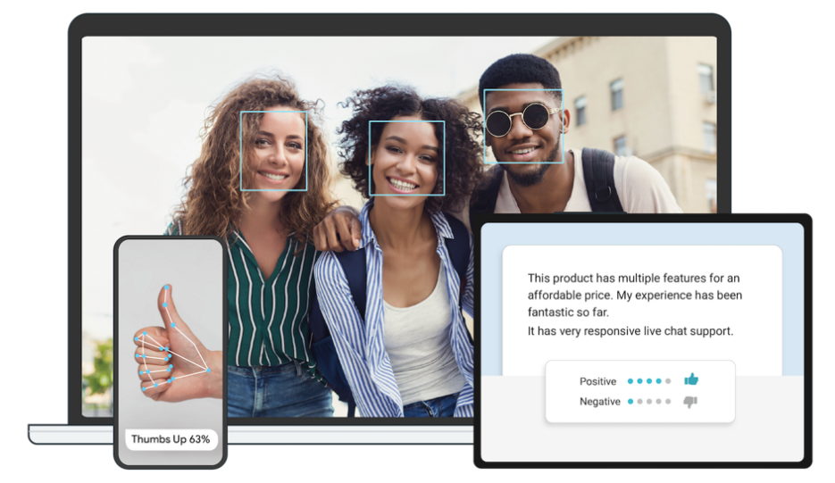
MediaPipe is an open-source framework designed for building multimedia machine learning pipelines. It is cross-platform and can run on mobile devices, workstations, and servers, with support for mobile GPU acceleration. MediaPipe is compatible with inference engines such as TensorFlow and TensorFlow Lite, allowing seamless integration with models from both platforms. Additionally, it offers GPU acceleration on mobile and embedded platforms.
7.1.1.2 Pros and Cons
Advantages of MediaPipe
MediaPipe supports various platforms and languages, including iOS, Android, C++, Python, JAVAScript, Coral, etc.
The performance is fast, and the model can generally run in real time.
Both the model and code allow for high reusability.
Disadvantages of MediaPipe
For mobile devices, MediaPipe will occupy 10 MB or more.
It heavily depends on TensorFlow, and switching to another machine learning framework would require significant code changes.
The framework uses static graphs, which improve efficiency but also make it more difficult to detect errors.
7.1.1.3 MediaPipe Usage Workflow
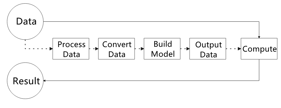
The figure below shows how to use MediaPipe. The solid line represents the part to be coded, and the dotted line indicates the part not to be coded. MediaPipe can offer the result and the function realization framework quickly.
Dependency
MediaPipe relies on OpenCV for video processing and FFMPEG for audio data processing. It also has other dependencies, such as OpenGL/Metal, TensorFlow, Eigen, and others.
It is recommended to gain a basic understanding of OpenCV before starting with MediaPipe. Information about OpenCV can be found in the folder: Basic Course / OpenCV Computer Vision Lesson.
MediaPipe Solutions
Solutions are based on the open-source pre-constructed sample of TensorFlow or TFLite. MediaPipe Solutions is built upon a framework, which provides 16 Solutions, including face detection, Face Mesh, iris, hand, posture, human body, and so on.
7.1.1.4 Websites for MediaPipe Learning
MediaPipe Official Website: https://developers.google.com/mediapipe
MediaPipe Wiki: http://i.bnu.edu.cn/wiki/index.php?title=Mediapipe
MediaPipe github: https://github.com/google/mediapipe
dlib Official Website: http://dlib.net/
dlib github: https://github.com/davisking/dlib
7.1.2 Background Segmentation
In this lesson, MediaPipe’s Selfie Segmentation model is used to segment trained models from the background and then apply a virtual background, such as a face or a hand.
7.1.2.1 Experiment Overview
First, the MediaPipe selfie segmentation model is imported, and real-time video is obtained by subscribing to the camera topic.
Next, the image is processed, and the segmentation mask is drawn onto the background image. Bilateral filtering is used to improve the segmentation around the edges.
Finally, the background is replaced with a virtual one.
7.1.2.2 Operation Steps
Power on the robot and connect it via the VNC remote control software. For detailed information, please refer to the section 1.7.2 AP Mode Connection Steps in the user manual.
Click the terminal icon
 in the system desktop to open a command-line window.
Enter the command to disable the app auto-start service.
~/.stop_ros.sh
Enter the command to start the camera node:
ros2 launch peripherals depth_camera.launch.py
Open a new command-line terminal, enter the command, and press Enter to run the program.
cd ~/ros2_ws/src/example/example/mediapipe_example && python3 self_segmentation.py
To exit this feature, press the Esc key in the image window to close the camera feed.
To exit the feature, press Ctrl+C in the terminal. If the program does not close successfully, try pressing Ctrl+C again.
7.1.2.3 Project Outcome
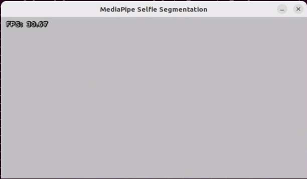
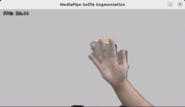
After starting the feature, the entire returned image is transformed into a uniform gray virtual background. Once a real hand enters the camera’s field of view, the system immediately and accurately detects and separates the hand from the background.
7.1.2.4 Program Analysis
The program file of the feature is located at: /ros2_ws/src/example/example/mediapipe_example/self_segmentation.py
Functions
Main:
def main():
    node = SegmentationNode('self_segmentation')
    try:
        rclpy.spin(node)
    except KeyboardInterrupt:
        node.destroy_node()
        rclpy.shutdown()
        print('shutdown')
    finally:
        print('shutdown finish')
Starts the background control node.
Class
SegmentationNode:
class SegmentationNode(Node):
    def __init__(self, name):
        rclpy.init()
        super().__init__(name)
        self.running = True
        self.bridge = CvBridge()
        self.mp_selfie_segmentation = mp.solutions.selfie_segmentation
        self.mp_drawing = mp.solutions.drawing_utils
        self.fps = fps.FPS()
        self.image_queue = queue.Queue(maxsize=2)
        self.BG_COLOR = (192, 192, 192)  # gray
        self.image_sub = self.create_subscription(Image, '/depth_cam/rgb0/image_raw', self.image_callback, 1)
        self.get_logger().info('\033[1;32m%s\033[0m' % 'start')
        threading.Thread(target=self.main, daemon=True).start()
Init:
    def __init__(self, name):
        rclpy.init()
        super().__init__(name)
        self.running = True
        self.bridge = CvBridge()
        self.mp_selfie_segmentation = mp.solutions.selfie_segmentation
        self.mp_drawing = mp.solutions.drawing_utils
        self.fps = fps.FPS()
        self.image_queue = queue.Queue(maxsize=2)
        self.BG_COLOR = (192, 192, 192)  # gray
        self.image_sub = self.create_subscription(Image, '/depth_cam/rgb0/image_raw', self.image_callback, 1)
        self.get_logger().info('\033[1;32m%s\033[0m' % 'start')
        threading.Thread(target=self.main, daemon=True).start()
Initializes the parameters required for background segmentation, calls the image callback function, and starts the model inference function.
image_callback:
    def image_callback(self, ros_image):
        cv_image = self.bridge.imgmsg_to_cv2(ros_image, "rgb8")
        rgb_image = np.array(cv_image, dtype=np.uint8)
        if self.image_queue.full():
            # If the queue is full, remove the oldest image
            self.image_queue.get()
            # Put the image into the queue
        self.image_queue.put(rgb_image)
The image callback function is used to read data from the camera node and enqueue it.
Main:
    def main(self):
        with self.mp_selfie_segmentation.SelfieSegmentation(
            model_selection=1) as selfie_segmentation:
            bg_image = None
            while self.running:
                try:
                    image = self.image_queue.get(block=True, timeout=1)
                except queue.Empty:
                    if not self.running:
                        break
                    else:
                        continue
                # To improve performance, optionally mark the image as not writeable to
                # Pass by reference.
                image.flags.writeable = False
                results = selfie_segmentation.process(image)
                image.flags.writeable = True
                image = cv2.cvtColor(image, cv2.COLOR_RGB2BGR)
                # Draw selfie segmentation on the background image.
                # To improve segmentation around boundaries, consider applying a joint
                # Bilateral filter to "results.segmentation_mask" with "image".
                condition = np.stack(
                        (results.segmentation_mask,) * 3, axis=-1) > 0.1
                # The background can be customized.
                #   a) Load an image (with the same width and height of the input image) to
                #      be the background, e.g., bg_image = cv2.imread('/path/to/image/file')
                #   b) Blur the input image by applying image filtering, e.g.,
                #      bg_image = cv2.GaussianBlur(image,(55,55),0)
                if bg_image is None:
                  bg_image = np.zeros(image.shape, dtype=np.uint8)
                  bg_image[:] = self.BG_COLOR
                output_image = np.where(condition, image, bg_image)
                self.fps.update()
                result_image = self.fps.show_fps(output_image)
                cv2.imshow('MediaPipe Selfie Segmentation', result_image)
                key = cv2.waitKey(1)
                if key == ord('q') or key == 27:  # Press Q or Esc to quit)
                    break
        cv2.destroyAllWindows()
        rclpy.shutdown()
The model within mediapipe is loaded, the image is passed as input, and the output image is displayed using opencv after processing.
7.1.3 3D Object Detection
7.1.3.1 Experiment Overview
First, import MediaPipe’s 3D Objection and subscribe to the topic messages to obtain the real-time camera feed.
Next, apply preprocessing steps such as image flipping, and then perform 3D object detection on the images.
Finally, draw 3D bounding boxes on the detected objects in the image. In this section, a cup is used for demonstration.
7.1.3.2 Operation Steps
Power on the robot and connect it via the VNC remote control software. For detailed information, please refer to the section 1.7.2 AP Mode Connection Steps in the user manual.
Click the terminal icon
in the system desktop to open a command-line window.Enter the command to disable the app auto-start service.
~/.stop_ros.sh
Enter the command to start the camera node:
ros2 launch peripherals depth_camera.launch.py
Open a new command-line terminal, enter the command, and press Enter to run the program.
cd ~/ros2_ws/src/example/example/mediapipe_example && python3 objectron.py
To exit this feature, press the Esc key in the image window to close the camera feed.
To exit the feature, press Ctrl+C in the terminal. If the program does not close successfully, try pressing Ctrl+C again.
7.1.3.3 Project Outcome
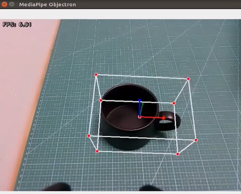
Once the program starts, a 3D bounding box will appear around the detected object in the camera view. Currently, four types of objects are supported: a cup with a handle, a shoe, a chair, and a camera. For example, when detecting a cup, the effect is shown as follows:
7.1.3.4 Program Analysis
The program file of the feature is located at: /ros2_ws/src/example/example/mediapipe_example/objectron.py
Functions
Main:
def main():
    node = ObjectronNode('objectron')
    try:
        rclpy.spin(node)
    except KeyboardInterrupt:
        node.destroy_node()
        rclpy.shutdown()
        print('shutdown')
    finally:
        print('shutdown finish')
Used to start the 3D detection node.
Class
ObjectronNode:
class ObjectronNode(Node):
    def __init__(self, name):
        rclpy.init()
        super().__init__(name)
        self.running = True
        self.bridge = CvBridge()
        self.mp_objectron = mp.solutions.objectron
        self.mp_drawing = mp.solutions.drawing_utils
        self.fps = fps.FPS()
        self.image_queue = queue.Queue(maxsize=2)
        self.image_sub = self.create_subscription(Image, '/depth_cam/rgb0/image_raw', self.image_callback, 1)
        self.get_logger().info('\033[1;32m%s\033[0m' % 'start')
        threading.Thread(target=self.main, daemon=True).start()
Init:
    def __init__(self, name):
        rclpy.init()
        super().__init__(name)
        self.running = True
        self.bridge = CvBridge()
        self.mp_objectron = mp.solutions.objectron
        self.mp_drawing = mp.solutions.drawing_utils
        self.fps = fps.FPS()
        self.image_queue = queue.Queue(maxsize=2)
        self.image_sub = self.create_subscription(Image, '/depth_cam/rgb0/image_raw', self.image_callback, 1)
        self.get_logger().info('\033[1;32m%s\033[0m' % 'start')
        threading.Thread(target=self.main, daemon=True).start()
Initializes the parameters required for 3D recognition, calls the image callback function, and starts the model inference function.
image_callback:
    def image_callback(self, ros_image):
        cv_image = self.bridge.imgmsg_to_cv2(ros_image, "rgb8")
        rgb_image = np.array(cv_image, dtype=np.uint8)
        if self.image_queue.full():
            # If the queue is full, remove the oldest image
            self.image_queue.get()
            # Put the image into the queue
        self.image_queue.put(rgb_image)
The image callback function is used to read data from the camera node and enqueue it.
Main :
    def main(self):
        with self.mp_objectron.Objectron(static_image_mode=False,
                                max_num_objects=1,
                                min_detection_confidence=0.4,
                                min_tracking_confidence=0.5,
                                model_name='Cup') as objectron:
            while self.running:
                try:
                    image = self.image_queue.get(block=True, timeout=1)
                except queue.Empty:
                    if not self.running:
                        break
                    else:
                        continue
                # To improve performance, optionally mark the image as not writeable to
                # pass by reference.
                image.flags.writeable = False
                results = objectron.process(image)

                # Draw the box landmarks on the image.
                image.flags.writeable = True
                image = cv2.cvtColor(image, cv2.COLOR_RGB2BGR)
                if results.detected_objects:
                    for detected_object in results.detected_objects:
                        self.mp_drawing.draw_landmarks(
                          image, detected_object.landmarks_2d, self.mp_objectron.BOX_CONNECTIONS)
                        self.mp_drawing.draw_axis(image, detected_object.rotation,
                                             detected_object.translation)
                self.fps.update()
                result_image = self.fps.show_fps(cv2.flip(image, 1))
                # Flip the image horizontally for a selfie-view display.
                cv2.imshow('MediaPipe Objectron', result_image)
                key = cv2.waitKey(1)
                if key == ord('q') or key == 27:  # Press Q or Esc to quit
                    break

        cv2.destroyAllWindows()
        rclpy.shutdown()
Loads the model from MediaPipe, feeds the image into the model, and then uses OpenCV to draw object edges and display the results.
7.1.4 3D Face Detection
In this program, MediaPipe’s face detection model is utilized to detect a human face within the camera image.
MediaPipe Face Detection is a high-speed face detection solution that provides six key landmarks and supports multiple faces. Based on BlazeFace, a lightweight and efficient face detector optimized for mobile GPU inference.
7.1.4.1 Experiment Overview
First, import the MediaPipe face detection model and subscribe to the topic messages to obtain the real-time camera feed.
Next, use OpenCV to process the image, including flipping and converting the color space.
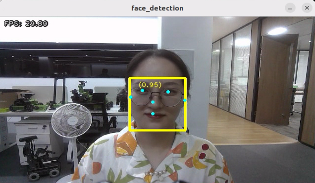
Next, the system compares the detection confidence against the model’s minimum threshold to determine if face detection is successful. Once a face is detected, the system will analyze the set of facial features. Each face is represented as a detection message that contains a bounding box and six key landmarks, including right eye, left eye, nose tip, mouth center, right ear region, and left ear region.
Finally, the face will be outlined with a bounding box, and the six key landmarks will be marked on the image.
7.1.4.2 Operation Steps
Power on the robot and connect it via the VNC remote control software. For detailed information, please refer to the section 1.7.2 AP Mode Connection Steps in the user manual.
Click the terminal icon
in the system desktop to open a command-line window.Enter the command to disable the app auto-start service.
~/.stop_ros.sh
Enter the command to start the camera node:
ros2 launch peripherals depth_camera.launch.py
Open a new command-line terminal, enter the command, and press Enter to run the program.
cd ~/ros2_ws/src/example/example/mediapipe_example && python3 face_detect.py
To exit this feature, press the Esc key in the image window to close the camera feed.
To exit the feature, press Ctrl+C in the terminal. If the program does not close successfully, try pressing Ctrl+C again.
7.1.4.3 Project Outcome
Once the feature is activated, the depth camera is immediately powered on and the face detection algorithm is executed. As soon as a face is detected, the robot accurately highlights the face region in the returned image with a prominent frame.
7.1.4.4 Program Analysis
The program file of the feature is located at: /ros2_ws/src/example/example/mediapipe_example/face_detect.py
Functions
Main:
def main():
    node = FaceDetectionNode('face_detection')
    try:
        rclpy.spin(node)
    except KeyboardInterrupt:
        node.destroy_node()
        rclpy.shutdown()
        print('shutdown')
    finally:
        print('shutdown finish')
Launches the face detection node.
Class
FaceDetectionNode:
    def __init__(self, name):
        rclpy.init()
        super().__init__(name)
        self.running = True
        self.bridge = CvBridge()
        model_path = os.path.join(os.path.abspath(os.path.split(os.path.realpath(__file__))[0]), 'model/detector.tflite')
        base_options = python.BaseOptions(model_asset_path=model_path)
        options = vision.FaceDetectorOptions(base_options=base_options)
        self.detector = vision.FaceDetector.create_from_options(options)
        self.fps = fps.FPS()
        self.image_queue = queue.Queue(maxsize=2)
        self.image_sub = self.create_subscription(Image, '/depth_cam/rgb0/image_raw', self.image_callback, 1)
        self.get_logger().info('\033[1;32m%s\033[0m' % 'start')
        threading.Thread(target=self.main, daemon=True).start()
Init:
        super().__init__(name)
        self.running = True
        self.bridge = CvBridge()
        model_path = os.path.join(os.path.abspath(os.path.split(os.path.realpath(__file__))[0]), 'model/detector.tflite')
        base_options = python.BaseOptions(model_asset_path=model_path)
        options = vision.FaceDetectorOptions(base_options=base_options)
        self.detector = vision.FaceDetector.create_from_options(options)
        self.fps = fps.FPS()
        self.image_queue = queue.Queue(maxsize=2)
        self.image_sub = self.create_subscription(Image, '/depth_cam/rgb0/image_raw', self.image_callback, 1)
        self.get_logger().info('\033[1;32m%s\033[0m' % 'start')
        threading.Thread(target=self.main, daemon=True).start()
Initializes the parameters required for face recognition, calls the image callback function, and starts the model inference function.
image_callback:
    def image_callback(self, ros_image):
        cv_image = self.bridge.imgmsg_to_cv2(ros_image, "rgb8")
        rgb_image = np.array(cv_image, dtype=np.uint8)
        if self.image_queue.full():
            # If the queue is full, discard the oldest image
            self.image_queue.get()
            # Put the image into the queue
        self.image_queue.put(rgb_image)
The image callback function is used to read data from the camera node and enqueue it.
Main:
    def main(self):
        while self.running:
            try:
                image = self.image_queue.get(block=True, timeout=1)
            except queue.Empty:
                if not self.running:
                    break
                else:
                    continue
            image = cv2.flip(image, 1)
            mp_image = mp.Image(image_format=mp.ImageFormat.SRGB, data=image)
            detection_result = self.detector.detect(mp_image)

            annotated_image = visualize(image, detection_result)
            self.fps.update()
            result_image = self.fps.show_fps(cv2.cvtColor(annotated_image, cv2.COLOR_RGB2BGR))
            cv2.imshow('face_detection', result_image)
            key = cv2.waitKey(1)
            if key == ord('q') or key == 27:  # Press Q or Esc to quit
              break

        cv2.destroyAllWindows()
        rclpy.shutdown()
Loads the model from MediaPipe, feeds the image into it, and uses OpenCV to draw facial keypoints and display the returned video feed.
7.1.5 3D Face Detection
In this program, MediaPipe Face Mesh is utilized to detect the human face within the camera image.
MediaPipe Face Mesh is a powerful model capable of estimating 468 3D facial features, even when deployed on a mobile device. It uses machine learning (ML) to infer 3D facial structure. This model leverages a lightweight architecture and GPU acceleration to deliver critical real-time performance.
Additionally, the solution is bundled with a face transformation module that bridges the gap between facial landmark estimation and practical real-time augmented reality (AR) applications. It establishes a metric 3D space and uses the screen positions of facial landmarks to estimate face transformations within that space. The face transformation data consists of common 3D primitives, including a facial pose transformation matrix and a triangulated face mesh.
7.1.5.1 Experiment Overview
First, it’s important to understand that the machine learning pipeline used here, which can be thought of as a linear process, consists of two real-time deep neural network models working in tandem: One is a detector that processes the full image to locate faces. The other is a face landmark model that operates on those locations and uses regression to predict an approximate 3D surface.
For the 3D face landmarks, transfer learning was applied, and a multi-task network was trained. This network simultaneously predicts 3D landmark coordinates on synthetic rendered data and 2D semantic contours on annotated real-world data. As a result, the network is informed by both synthetic and real-world data, allowing for accurate 3D landmark prediction.
The 3D landmark model takes cropped video frames as input, without requiring additional depth input. It outputs the positions of 3D points along with a probability score indicating whether a face is present and properly aligned in the input.
After importing the face mesh model, you can subscribe to the topic messages to obtain the real-time camera feed.
The image is processed through operations such as flipping and color space conversion. Then, by comparing the face detection confidence to a predefined threshold, it determines whether a face has been successfully detected.
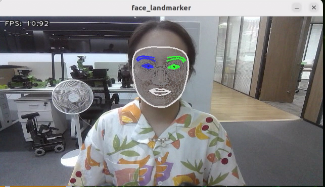
Finally, a 3D mesh is rendered over the detected face in the video feed.
7.1.5.2 Operation Steps
Power on the robot and connect it via the VNC remote control software. For detailed information, please refer to the section 1.7.2 AP Mode Connection Steps in the user manual.
Click the terminal icon
in the system desktop to open a command-line window.Enter the command to disable the app auto-start service.
~/.stop_ros.sh
Enter the command to start the camera node:
ros2 launch peripherals depth_camera.launch.py
Open a new command-line terminal, enter the command, and press Enter to run the program.
cd ~/ros2_ws/src/example/example/mediapipe_example && python3 face_mesh.py
To exit this feature, press the Esc key in the image window to close the camera feed.
To exit the feature, press Ctrl+C in the terminal. If the program does not close successfully, try pressing Ctrl+C again.
7.1.5.3 Project Outcome
Once the feature is started, the depth camera detects a face and highlights it with a bounding box in the returned video feed.
7.1.5.4 Program Analysis
The program file of the feature is located at: /ros2_ws/src/example/example/mediapipe_example/face_mesh.py
Functions
Main:
def main():
    node = FaceMeshNode('face_landmarker')
    try:
        rclpy.spin(node)
    except KeyboardInterrupt:
        node.destroy_node()
        rclpy.shutdown()
        print('shutdown')
    finally:
        print('shutdown finish')
Used to launch the 3D face detection node.
Class
FaceMeshNode:
class FaceMeshNode(Node):
    def __init__(self, name):
        rclpy.init()
        super().__init__(name)
        self.running = True
        self.bridge = CvBridge()
        model_path = os.path.join(os.path.abspath(os.path.split(os.path.realpath(__file__))[0]), 'model/face_landmarker_v2_with_blendshapes.task')
        base_options = python.BaseOptions(model_asset_path=model_path)
        options = vision.FaceLandmarkerOptions(base_options=base_options,
                                       output_face_blendshapes=True,
                                       output_facial_transformation_matrixes=True,
                                       num_faces=1)
Init:
        rclpy.init()
        super().__init__(name)
        self.running = True
        self.bridge = CvBridge()
        model_path = os.path.join(os.path.abspath(os.path.split(os.path.realpath(__file__))[0]), 'model/face_landmarker_v2_with_blendshapes.task')
        base_options = python.BaseOptions(model_asset_path=model_path)
        options = vision.FaceLandmarkerOptions(base_options=base_options,
                                       output_face_blendshapes=True,
                                       output_facial_transformation_matrixes=True,
                                       num_faces=1)
        self.detector = vision.FaceLandmarker.create_from_options(options)

        self.fps = fps.FPS()

        self.image_queue = queue.Queue(maxsize=2)
        self.image_sub = self.create_subscription(Image, '/depth_cam/rgb0/image_raw', self.image_callback, 1)
        self.get_logger().info('\033[1;32m%s\033[0m' % 'start')
        threading.Thread(target=self.main, daemon=True).start()
Initializes the parameters required for 3D face detection, calls the image callback function, and starts the model inference function.
image_callback:
    def image_callback(self, ros_image):
        cv_image = self.bridge.imgmsg_to_cv2(ros_image, "rgb8")
        rgb_image = np.array(cv_image, dtype=np.uint8)
        if self.image_queue.full():
            # If the queue is full, discard the oldest image
            self.image_queue.get()
            # Put the image into the queue
        self.image_queue.put(rgb_image)
The image callback function is used to read data from the camera node and enqueue it.
Main :
    def main(self):
        while self.running:
            try:
                image = self.image_queue.get(block=True, timeout=1)
            except queue.Empty:
                if not self.running:
                    break
                else:
                    continue
            image = cv2.flip(image, 1)
            mp_image = mp.Image(image_format=mp.ImageFormat.SRGB, data=image)
            detection_result = self.detector.detect(mp_image)
            annotated_image = draw_face_landmarks_on_image(image, detection_result)
            self.fps.update()
            result_image = self.fps.show_fps(cv2.cvtColor(annotated_image, cv2.COLOR_RGB2BGR))
            cv2.imshow('face_landmarker', result_image)
            key = cv2.waitKey(1)
            if key == ord('q') or key == 27:  # Press Q or Esc to quit
                break
        cv2.destroyAllWindows()
        rclpy.shutdown()
Loads the model from MediaPipe, feeds the image into it, and uses OpenCV to draw facial keypoints and display the returned video feed.
7.1.6 Hand Keypoint Detection
In this lesson, MediaPipe’s hand detection model is used to display hand keypoints and the connecting lines between them on the returned image.
MediaPipe Hands is a high-fidelity hand and finger tracking model. It uses machine learning (ML) to infer 21 3D landmarks of a hand from a single frame.
7.1.6.1 Experiment Overview
First, it’s important to understand that MediaPipe’s palm detection model utilizes a machine learning pipeline composed of multiple models, which is a linear model, similar to an assembly line. The model processes the entire image and returns an oriented hand bounding box. The hand landmark model then operates on the cropped image region defined by the palm detector and returns high-fidelity 3D hand keypoints.
After importing the hand detection model, the system subscribes to topic messages to acquire real-time camera images. The images are then processed with flipping and color space conversion, which greatly reduces the need for data augmentation for the hand landmark model.
In addition, the pipeline can generate crops based on the hand landmarks recognized in the previous frame. The palm detection model is only invoked to re-locate the hand when the landmark model can no longer detect its presence.
Next, the system compares the detection confidence against the model’s minimum threshold to determine if hand detection is successful.
Finally, it detects and draws the hand keypoints on the output image.
7.1.6.2 Operation Steps
Power on the robot and connect it via the VNC remote control software. For detailed information, please refer to the section 1.7.2 AP Mode Connection Steps in the user manual.
Click the terminal icon
in the system desktop to open a command-line window.Enter the command to disable the app auto-start service.
~/.stop_ros.sh
Enter the command to start the camera node:
ros2 launch peripherals depth_camera.launch.py
Open a new command-line terminal, enter the command, and press Enter to run the program.
cd ~/ros2_ws/src/example/example/mediapipe_example && python3 hand.py
To exit this feature, press the Esc key in the image window to close the camera feed.
To exit the feature, press Ctrl+C in the terminal. If the program does not close successfully, try pressing Ctrl+C again.
7.1.6.3 Project Outcome
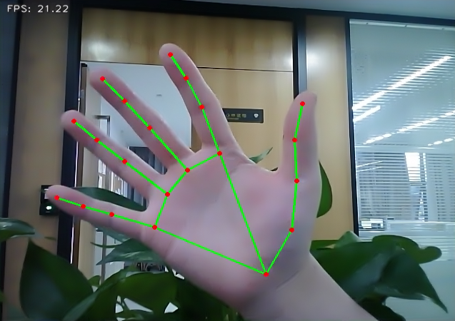
Once the feature is activated, the depth camera is immediately powered on, and the hand detection model is triggered for hand detection. Once a hand is successfully detected, the system intelligently marks the key points of the hand in the returned image and automatically draws the connecting lines between these points.
7.1.6.4 Program Analysis
The program file of the feature is located at: /ros2_ws/src/example/example/mediapipe_example/hand.py
Functions
Main:
def main():
    node = HandNode('hand_landmarker')
    try:
        rclpy.spin(node)
    except KeyboardInterrupt:
        node.destroy_node()
        rclpy.shutdown()
        print('shutdown')
    finally:
        print('shutdown finish')
Used to launch the 3D face detection node.
Class
HandNode:
class HandNode(Node):
    def __init__(self, name):
        rclpy.init()
        super().__init__(name)
        self.running = True
        self.bridge = CvBridge()
        model_path = os.path.join(os.path.abspath(os.path.split(os.path.realpath(__file__))[0]), 'model/hand_landmarker.task')
        base_options = python.BaseOptions(model_asset_path=model_path)
        options = vision.HandLandmarkerOptions(base_options=base_options, num_hands=2)
        self.detector = vision.HandLandmarker.create_from_options(options)
        self.fps = fps.FPS()
        self.image_queue = queue.Queue(maxsize=2)
        self.image_sub = self.create_subscription(Image, '/depth_cam/rgb0/image_raw', self.image_callback, 1)
        self.get_logger().info('\033[1;32m%s\033[0m' % 'start')
Init:
        rclpy.init()
        super().__init__(name)
        self.running = True
        self.bridge = CvBridge()
        model_path = os.path.join(os.path.abspath(os.path.split(os.path.realpath(__file__))[0]), 'model/hand_landmarker.task')
        base_options = python.BaseOptions(model_asset_path=model_path)
        options = vision.HandLandmarkerOptions(base_options=base_options, num_hands=2)
        self.detector = vision.HandLandmarker.create_from_options(options)
        self.fps = fps.FPS()
        self.image_queue = queue.Queue(maxsize=2)
        self.image_sub = self.create_subscription(Image, '/depth_cam/rgb0/image_raw', self.image_callback, 1)
        self.get_logger().info('\033[1;32m%s\033[0m' % 'start')
        threading.Thread(target=self.main, daemon=True).start()

    def image_callback(self, ros_image):
        cv_image = self.bridge.imgmsg_to_cv2(ros_image, "rgb8")
        rgb_image = np.array(cv_image, dtype=np.uint8)
        if self.image_queue.full():
            # If the queue is full, remove the oldest image
            self.image_queue.get()
            # Put the image into the queue
        self.image_queue.put(rgb_image)
Initializes the parameters required for hand keypoints detection, calls the image callback function, and starts the model inference function.
image_callback:
    def image_callback(self, ros_image):
        cv_image = self.bridge.imgmsg_to_cv2(ros_image, "rgb8")
        rgb_image = np.array(cv_image, dtype=np.uint8)
        if self.image_queue.full():
            # If the queue is full, remove the oldest image
            self.image_queue.get()
            # Put the image into the queue
        self.image_queue.put(rgb_image)
The image callback function is used to read data from the camera node and enqueue it.
Main :
    def main(self):
        while self.running:
            try:
                image = self.image_queue.get(block=True, timeout=1)
            except queue.Empty:
                if not self.running:
                    break
                else:
                    continue
            image = cv2.flip(image, 1)
            mp_image = mp.Image(image_format=mp.ImageFormat.SRGB, data=image)
            detection_result = self.detector.detect(mp_image)
            annotated_image = draw_hand_landmarks_on_image(image, detection_result)
            self.fps.update()
            result_image = self.fps.show_fps(cv2.cvtColor(annotated_image, cv2.COLOR_RGB2BGR))
            cv2.imshow('hand_landmarker', result_image)
            key = cv2.waitKey(1)
            if key == ord('q') or key == 27:  # Press Q or Esc to quit
                break
        cv2.destroyAllWindows()
        rclpy.shutdown()
Loads the model from MediaPipe, feeds the image into it, and uses OpenCV to draw the hand’s keypoints and display the returned video feed.
7.1.7 Body Keypoint Detection
In this lesson, MediaPipe’s pose detection model is used to detect body landmarks and display them on the video feed.
MediaPipe Pose is a high-fidelity body pose tracking model. Powered by BlazePose, it infers 33 3D landmarks across the full body from RGB input. This research also supports the ML Kit Pose Detection API.
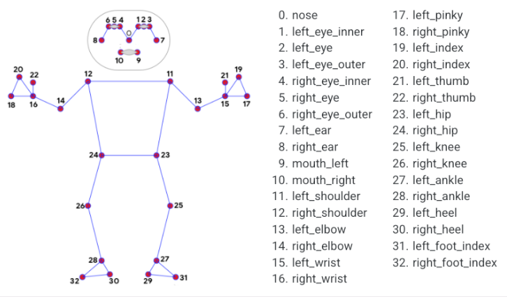
7.1.7.1 Experiment Overview
First, import the pose detection model.
Then, the program applies image preprocessing such as flipping and converting the color space. By comparing against a minimum detection confidence threshold, it determines whether the human body is successfully detected.
Next, it uses a minimum tracking confidence threshold to decide whether the detected pose can be reliably tracked. If not, the model will automatically re-invoke detection on the next input image.
The pipeline first identifies the region of interest (ROI) containing the person’s pose in the frame using a detector. The tracker then uses the cropped ROI image as input to predict pose landmarks and segmentation masks within that area. For video applications, the detector is only invoked when necessary—such as for the first frame or when the tracker fails to identify a pose from the previous frame. For all other frames, the ROI is derived from the previously tracked landmarks.
After importing the MediaPipe pose detection model, you can subscribe to the topic messages to obtain the real-time video stream from the camera.
Finally, it identifies and draws the body landmarks on the image.
7.1.7.2 Operation Steps
Power on the robot and connect it via the VNC remote control software. For detailed information, please refer to the section 1.7.2 AP Mode Connection Steps in the user manual.
Click the terminal icon
in the system desktop to open a command-line window.Enter the command to disable the app auto-start service.
~/.stop_ros.sh
Enter the command to start the camera node:
ros2 launch peripherals depth_camera.launch.py
Open a new command-line terminal, enter the command, and press Enter to run the program.
cd ~/ros2_ws/src/example/example/mediapipe_example && python3 pose.py
To exit this feature, press the Esc key in the image window to close the camera feed.
To exit the feature, press Ctrl+C in the terminal. If the program does not close successfully, try pressing Ctrl+C again.
7.1.7.3 Project Outcome
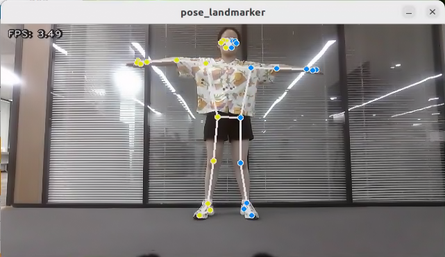
Once the feature is activated, the depth camera is immediately powered on, and human pose detection is initiated. Once the human body is successfully detected, the system quickly and accurately marks the key body points in the returned image and automatically draws the connecting lines between these points, forming a human pose skeleton.
7.1.7.4 Program Analysis
The program file of the feature is located at: /ros2_ws/src/example/example/mediapipe_example/pose.py
Functions
Main:
def main():
    node = PoseNode('pose_landmarker')
    try:
        rclpy.spin(node)
    except KeyboardInterrupt:
        node.destroy_node()
        rclpy.shutdown()
        print('shutdown')
    finally:
        print('shutdown finish')
Used to launch the 3D face detection node.
Class
PoseNode:
class PoseNode(Node):
    def __init__(self, name):
        rclpy.init()
        super().__init__(name)
        self.running = True
        self.bridge = CvBridge()
        model_path = os.path.join(os.path.abspath(os.path.split(os.path.realpath(__file__))[0]), 'model/pose_landmarker.task')
        base_options = python.BaseOptions(model_asset_path=model_path)
        options = vision.PoseLandmarkerOptions(
            base_options=base_options,
            output_segmentation_masks=True)
        self.detector = vision.PoseLandmarker.create_from_options(options)
        self.fps = fps.FPS()
        self.image_queue = queue.Queue(maxsize=2)
        self.image_sub = self.create_subscription(Image, '/depth_cam/rgb0/image_raw', self.image_callback, 1)
Init:
    def __init__(self, name):
        rclpy.init()
        super().__init__(name)
        self.running = True
        self.bridge = CvBridge()
        model_path = os.path.join(os.path.abspath(os.path.split(os.path.realpath(__file__))[0]), 'model/pose_landmarker.task')
        base_options = python.BaseOptions(model_asset_path=model_path)
        options = vision.PoseLandmarkerOptions(
            base_options=base_options,
            output_segmentation_masks=True)
        self.detector = vision.PoseLandmarker.create_from_options(options)
        self.fps = fps.FPS()
        self.image_queue = queue.Queue(maxsize=2)
        self.image_sub = self.create_subscription(Image, '/depth_cam/rgb0/image_raw', self.image_callback, 1)
        self.get_logger().info('\033[1;32m%s\033[0m' % 'start')
        threading.Thread(target=self.main, daemon=True).start()
Initializes the parameters required for body keypoints detection, calls the image callback function, and starts the model inference function.
image_callback:
    def image_callback(self, ros_image):
        cv_image = self.bridge.imgmsg_to_cv2(ros_image, "rgb8")
        rgb_image = np.array(cv_image, dtype=np.uint8)
        if self.image_queue.full():
            # If the queue is full, remove the oldest image
            self.image_queue.get()
            # Put the image into the queue
        self.image_queue.put(rgb_image)
The image callback function is used to read data from the camera node and enqueue it.
Main:
    def main(self):
        while self.running:
            try:
                image = self.image_queue.get(block=True, timeout=1)
            except queue.Empty:
                if not self.running:
                    break
                else:
                    continue
            image = cv2.flip(image, 1)
            mp_image = mp.Image(image_format=mp.ImageFormat.SRGB, data=image)
            detection_result = self.detector.detect(mp_image)
            annotated_image = draw_pose_landmarks_on_image(image, detection_result)
            self.fps.update()
            result_image = self.fps.show_fps(cv2.cvtColor(annotated_image, cv2.COLOR_RGB2BGR))
            cv2.imshow('pose_landmarker', result_image)
            key = cv2.waitKey(1)
            if key == ord('q') or key == 27:  # Press Q or Esc to quit
                break
        cv2.destroyAllWindows()
        rclpy.shutdown()
Loads the model from MediaPipe, feeds the image into it, and uses OpenCV to draw facial keypoints and display the returned video feed.
7.1.8 Fingertip Trajectory Recognition
The robot uses MediaPipe’s hand detection model to recognize palm joints. Once a specific hand gesture is detected, the robot locks onto the fingertip in the image and begins tracking it, drawing the movement trajectory of the fingertip.
7.1.8.1 Experiment Overview
First, the MediaPipe hand detection model is called to process the camera feed.
Next, the image is flipped and processed to detect hand information within the frame. Based on the connections between hand landmarks, the finger angles are calculated to identify specific gestures.
Finally, once the designated gesture is recognized, the robot starts tracking and locking onto the fingertip, while displaying its movement trajectory in the video feed.
7.1.8.2 Operation Steps
Note
Commands must be entered with correct capitalization. The Tab key can be used to auto-complete keywords.
Power on the robot and connect it via the VNC remote control software. For detailed information, please refer to the section 1.7.2 AP Mode Connection Steps in the user manual.
Click the terminal icon
in the system desktop to open a command-line window.Enter the command to disable the app auto-start service.
~/.stop_ros.sh
Enter the command to start the camera node:
ros2 launch peripherals depth_camera.launch.py
Open a new command-line terminal, enter the command, and press Enter to run the program.
cd ~/ros2_ws/src/example/example/mediapipe_example && python3 hand_gesture.py
The program will launch the camera image interface. For details on the detection steps, please refer to section 7.1.8.3 Project Outcome in this document.
To exit this feature, press the Esc key in the image window to close the camera feed.
To exit the feature, press Ctrl+C in the terminal. If the program does not close successfully, try pressing Ctrl+C again.
7.1.8.3 Project Outcome
After starting the feature, place your hand within the camera’s field of view. Once the hand is detected, key points of the hand will be marked in the returned image.
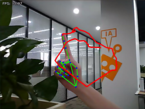
If the gesture 1, which involves extending the index finger, is detected, the robot will immediately enter recording mode. The system will track and display the movement of the fingertip in real time on the returned image using dynamic lines. This feature enables free drawing in the virtual space with simple gestures.
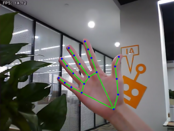
On the other hand, if the gesture 5, which involves an open hand forming the shape of the number 5, is detected, a clear command will be triggered. At this point, the recorded fingertip movement will be immediately erased, and the image will return to a state without any trace.
7.1.8.4 Program Analysis
The program file of the feature is located at: /ros2_ws/src/example/example/mediapipe_example/hand_gesture.py
Note
Before modifying the program, back up the original factory code. Do not modify the source code file directly to avoid robot malfunction due to incorrect parameter changes.
Functions
Main:
def main():
    node = HandGestureNode('hand_gesture')
    try:
        rclpy.spin(node)
    except KeyboardInterrupt:
        node.destroy_node()
        rclpy.shutdown()
        print('shutdown')
    finally:
        print('shutdown finish')
The main function is used to start the fingertip trajectory recognition node.
get_hand_landmarks:
def get_hand_landmarks(img, landmarks):
    """
    Convert landmarks from normalized output of Mediapipe to pixel coordinates.
    :param img: Image corresponding to pixel coordinates.
    :param landmarks: Normalized key points.
    :return:
    """
    h, w, _ = img.shape
    landmarks = [(lm.x * w, lm.y * h) for lm in landmarks]
    return np.array(landmarks)
Converts the normalized data from MediaPipe into pixel coordinates.
hand_angle:
def hand_angle(landmarks):
    """
    Calculate the bending angle of each finger.
    :param landmarks: The key points of the hand.
    :return: Each finger's angle.
    """
    angle_list = []
    # thumb
    angle_ = vector_2d_angle(landmarks[3] - landmarks[4], landmarks[0] - landmarks[2])
    angle_list.append(angle_)
    # index finger
    angle_ = vector_2d_angle(landmarks[0] - landmarks[6], landmarks[7] - landmarks[8])
    angle_list.append(angle_)
    # middle finger
    angle_ = vector_2d_angle(landmarks[0] - landmarks[10], landmarks[11] - landmarks[12])
    angle_list.append(angle_)
    # ring finger
    angle_ = vector_2d_angle(landmarks[0] - landmarks[14], landmarks[15] - landmarks[16])
    angle_list.append(angle_)
    # pinky finger
    angle_ = vector_2d_angle(landmarks[0] - landmarks[18], landmarks[19] - landmarks[20])
    angle_list.append(angle_)
    angle_list = [abs(a) for a in angle_list]
    return angle_list
After extracting the hand keypoints into the results variable, the keypoints need to undergo logical processing. By analyzing the angular relationships between the keypoints, the specific type of finger, such as the thumb or index finger, can be identified. The hand_angle function takes the landmarks of the results as input, and the vector_2d_angle function is used to calculate the angles between the corresponding keypoints. The following diagram shows the keypoints corresponding to the elements in the landmarks set:
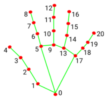
Taking the thumb’s angle as an example: vector_2d_angle The function is used to calculate the angle between the keypoints. The keypoints, landmarks[3], landmarks[4], landmarks[0], and landmarks[2] correspond to the points 3, 4, 0, and 2 in the hand feature extraction diagram. By calculating the angles between these key joints, the posture features of the thumb can be determined. Similarly, the processing logic for the remaining finger joints follows the same approach.
To ensure accurate recognition, the parameters and basic logic of angle addition and subtraction in the hand_angle function can be kept at their default settings.
h_gesture:
def h_gesture(angle_list):
    """
    Determine the gesture made by the fingers based on the two-dimensional features
    :param angle_list: The angles of each finger's bending
    :return : Gesture name string
    """
    thr_angle = 65.
    thr_angle_thumb = 53.
    thr_angle_s = 49.
    gesture_str = "none"
    if (angle_list[0] > thr_angle_thumb) and (angle_list[1] > thr_angle) and (angle_list[2] > thr_angle) and (
            angle_list[3] > thr_angle) and (angle_list[4] > thr_angle):
        gesture_str = "fist"
    elif (angle_list[0] < thr_angle_s) and (angle_list[1] < thr_angle_s) and (angle_list[2] > thr_angle) and (
            angle_list[3] > thr_angle) and (angle_list[4] > thr_angle):
        gesture_str = "hand_heart"
    elif (angle_list[0] < thr_angle_s) and (angle_list[1] < thr_angle_s) and (angle_list[2] > thr_angle) and (
            angle_list[3] > thr_angle) and (angle_list[4] < thr_angle_s):
        gesture_str = "nico-nico-ni"
    elif (angle_list[0] < thr_angle_s) and (angle_list[1] > thr_angle) and (angle_list[2] > thr_angle) and (
            angle_list[3] > thr_angle) and (angle_list[4] > thr_angle):
        gesture_str = "hand_heart"
    elif (angle_list[0] > 5) and (angle_list[1] < thr_angle_s) and (angle_list[2] > thr_angle) and (
            angle_list[3] > thr_angle) and (angle_list[4] > thr_angle):
        gesture_str = "one"
    elif (angle_list[0] > thr_angle_thumb) and (angle_list[1] < thr_angle_s) and (angle_list[2] < thr_angle_s) and (
            angle_list[3] > thr_angle) and (angle_list[4] > thr_angle):
        gesture_str = "two"
    elif (angle_list[0] > thr_angle_thumb) and (angle_list[1] < thr_angle_s) and (angle_list[2] < thr_angle_s) and (
            angle_list[3] < thr_angle_s) and (angle_list[4] > thr_angle):
        gesture_str = "three"
    elif (angle_list[0] > thr_angle_thumb) and (angle_list[1] > thr_angle) and (angle_list[2] < thr_angle_s) and (
            angle_list[3] < thr_angle_s) and (angle_list[4] < thr_angle_s):
        gesture_str = "OK"
    elif (angle_list[0] > thr_angle_thumb) and (angle_list[1] < thr_angle_s) and (angle_list[2] < thr_angle_s) and (
            angle_list[3] < thr_angle_s) and (angle_list[4] < thr_angle_s):
        gesture_str = "four"
    elif (angle_list[0] < thr_angle_s) and (angle_list[1] < thr_angle_s) and (angle_list[2] < thr_angle_s) and (
            angle_list[3] < thr_angle_s) and (angle_list[4] < thr_angle_s):
        gesture_str = "five"
    elif (angle_list[0] < thr_angle_s) and (angle_list[1] > thr_angle) and (angle_list[2] > thr_angle) and (
            angle_list[3] > thr_angle) and (angle_list[4] < thr_angle_s):
        gesture_str = "six"
    else:
        "none"
    return gesture_str
After identifying the types of fingers on the hand and determining their positions in the image, different gestures can be recognized by implementing the h_gestrue function.
In the h_gesture function shown in the diagram above, the parameters thr_angle = 65, thr_angle_thenum=53, and thr_angle_s=49 represent the angle threshold values for the corresponding gesture logic points. These values have been tested and found to provide stable recognition results. It is not recommended to change them. If the recognition performance is suboptimal, adjusting the values within ±5 is sufficient. The angle_list[0, 1, 2, 3, 4] corresponds to the five fingers of the hand.
Taking the gesture one as an example:

The code shown above represents the finger angle logic for the gesture one. angle_list[0]>5 checks whether the angle of the thumb joint feature point in the image is greater than 5. angle_list[1]<thr_angle_s checks whether the angle feature of the index finger joint is smaller than the predefined value thr_angle_s,angle_list[2]>thr_angle checks whether the angle feature of the middle finger joint is smaller than the predefined value thr_angle. The logic for the other two fingers, angle_list[3] and angle_list[4], follows a similar approach. When all these conditions are met, the current hand gesture is recognized as one. The recognition of other gestures follows a similar approach.
Each gesture has its own logic, but the overall framework is largely the same, and other gestures can be referenced based on this method.
draw_points:
def draw_points(img, points, thickness=4, color=(255, 0, 0)):
    points = np.array(points).astype(dtype=np.int64)
    if len(points) > 2:
        for i, p in enumerate(points):
            if i + 1 >= len(points):
                break
            cv2.line(img, p, points[i + 1], color, thickness)
Draw the currently detected hand shape along with all its key points.
Class
State:
class State(enum.Enum):
    NULL = 0
    START = 1
    TRACKING = 2
    RUNNING = 3
An enumeration class used to represent the current state of the program.
HandGestureNode:
class HandGestureNode(Node):
    def __init__(self, name):
        rclpy.init()
        super().__init__(name)
        self.running = True
        self.drawing = mp.solutions.drawing_utils

        self.hand_detector = mp.solutions.hands.Hands(
            static_image_mode=False,
            max_num_hands=1,
            min_tracking_confidence=0.05,
            min_detection_confidence=0.6
        )

        self.fps = fps.FPS()  # FPS calculator
        self.state = State.NULL
        self.points = []
        self.count = 0
        self.bridge = CvBridge()
        self.image_queue = queue.Queue(maxsize=2)
        self.image_sub = self.create_subscription(Image, '/depth_cam/rgb0/image_raw', self.image_callback, 1)
        self.get_logger().info('\033[1;32m%s\033[0m' % 'start')
        threading.Thread(target=self.main, daemon=True).start()
HandGestureNode is the fingertip trajectory recognition node. It contains three functions: an initialization function, a main function, and an image callback function.
Init:
    def __init__(self, name):
        rclpy.init()
        super().__init__(name)
        self.running = True
        self.drawing = mp.solutions.drawing_utils

        self.hand_detector = mp.solutions.hands.Hands(
            static_image_mode=False,
            max_num_hands=1,
            min_tracking_confidence=0.05,
            min_detection_confidence=0.6
        )

        self.fps = fps.FPS()  # FPS calculator
        self.state = State.NULL
        self.points = []
        self.count = 0
        self.bridge = CvBridge()
        self.image_queue = queue.Queue(maxsize=2)
        self.image_sub = self.create_subscription(Image, '/depth_cam/rgb0/image_raw', self.image_callback, 1)
        self.get_logger().info('\033[1;32m%s\033[0m' % 'start')
        threading.Thread(target=self.main, daemon=True).start()
Initializes all required components and calls the camera node.
7.1.9 Body Gesture Control
Using the human pose estimation model trained with the MediaPipe machine learning framework, the system detects the human pose in the camera feed and marks the relevant joint positions. Based on this, multiple actions can be recognized in sequence, allowing direct control of the robot through body gestures.
From the robot’s first-person perspective:
Raising the left arm causes the robot to move a certain distance to the right. Raising the right arm causes the robot to move a certain distance to the left. Raising the left leg causes the robot to move forward a certain distance. Raising the right leg causes the robot to move backward a certain distance.
7.1.9.1 Experiment Overview
First, the MediaPipe human pose estimation model is imported, and the camera feed is accessed by subscribing to the relevant topic messages.
MediaPipe is an open-source framework designed for building multimedia machine learning pipelines. It is cross-platform and can run on mobile devices, workstations, and servers, with support for mobile GPU acceleration. It also supports inference engines for TensorFlow and TensorFlow Lite.
Next, using the constructed model, key points of the human torso are detected in the camera feed. These key points are connected to visualize the torso, allowing the system to determine the body posture.
Finally, if the user performs a specific action, the robot responds accordingly.
7.1.9.2 Operation Steps
Note
Commands must be entered with correct capitalization. The Tab key can be used to auto-complete keywords.
Power on the robot and connect it via the VNC remote control software. For detailed information, please refer to the section 1.7.2 AP Mode Connection Steps in the user manual.
Click the terminal icon
in the system desktop to open a command-line window.Enter the command to disable the app auto-start service.
~/.stop_ros.sh
Enter the following command and press Enter to start the feature.
ros2 launch example body_control.launch.py
To exit this feature, press the Esc key in the image window to close the camera feed.
To exit the feature, press Ctrl+C in the terminal. If the program does not close successfully, try pressing Ctrl+C again.
7.1.9.3 Project Outcome
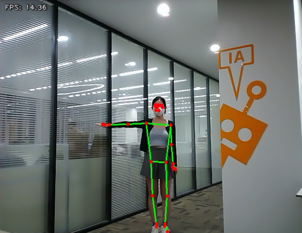
After starting the feature, stand within the camera’s field of view. When a human body is detected, the returned video feed will display the key points of the torso along with lines connecting them.
An intuitive body posture control logic has been designed for the robot, allowing control through simple body movements. The control instructions are as follows:
Left movement: Raise the right arm, and the robot will move to the left.
Right movement: Raise the left arm, and the robot will move to the right.
Forward movement: Raise the left leg, and the robot will move forward.
Backward movement: Raise the right leg, and the robot will move backward.
7.1.9.4 Program Analysis
The program file of the feature is located at: ros2_ws/src/example/example/body_control/include/body_control.py
Note
Before modifying the program, back up the original factory code. Do not modify the source code file directly to avoid robot malfunction due to incorrect parameter changes.
Functions
Main:
def main():
    node = BodyControlNode('body_control')
    rclpy.spin(node)
    node.destroy_node()
Starts the body motion control node.
get_joint_landmarks:
def get_joint_landmarks(img, landmarks):
    """
    Convert landmarks from medipipe's normalized output to pixel coordinates
    :param img: Picture corresponding to pixel coordinate
    :param landmarks: Normalized keypoint
    :return:
    """
    h, w, _ = img.shape
    landmarks = [(lm.x * w, lm.y * h) for lm in landmarks]
    return np.array(landmarks)
Converts the detected information into pixel coordinates.
joint_distance:
def joint_distance(landmarks):
    distance_list = []

    d1 = landmarks[LEFT_HIP] - landmarks[LEFT_SHOULDER]
    d2 = landmarks[LEFT_HIP] - landmarks[LEFT_WRIST]
    dis1 = d1[0]**2 + d1[1]**2
    dis2 = d2[0]**2 + d2[1]**2
    distance_list.append(round(dis1/dis2, 1))

    d1 = landmarks[RIGHT_HIP] - landmarks[RIGHT_SHOULDER]
    d2 = landmarks[RIGHT_HIP] - landmarks[RIGHT_WRIST]
    dis1 = d1[0]**2 + d1[1]**2
    dis2 = d2[0]**2 + d2[1]**2
    distance_list.append(round(dis1/dis2, 1))

    d1 = landmarks[LEFT_HIP] - landmarks[LEFT_ANKLE]
    d2 = landmarks[LEFT_ANKLE] - landmarks[LEFT_KNEE]
    dis1 = d1[0]**2 + d1[1]**2
    dis2 = d2[0]**2 + d2[1]**2
    distance_list.append(round(dis1/dis2, 1))

    d1 = landmarks[RIGHT_HIP] - landmarks[RIGHT_ANKLE]
    d2 = landmarks[RIGHT_ANKLE] - landmarks[RIGHT_KNEE]
    dis1 = d1[0]**2 + d1[1]**2
    dis2 = d2[0]**2 + d2[1]**2
    distance_list.append(round(dis1/dis2, 1))

    return distance_list
Calculates the distances between joints based on pixel coordinates.
Class
class BodyControlNode(Node):
    def __init__(self, name):
        rclpy.init()
        super().__init__(name, allow_undeclared_parameters=True, automatically_declare_parameters_from_overrides=True)
        self.name = name
        self.drawing = mp.solutions.drawing_utils
        self.body_detector = mp_pose.Pose(
            static_image_mode=False,
            min_tracking_confidence=0.7,
            min_detection_confidence=0.7)
        self.running = True
        self.fps = fps.FPS()  # FPS calculator
        signal.signal(signal.SIGINT, self.shutdown)

        self.move_finish = True
        self.stop_flag = False
        self.left_hand_count = []
        self.right_hand_count = []
        self.left_leg_count = []
        self.right_leg_count = []
This class represents the body control node.
Init:
    def __init__(self, name):
        rclpy.init()
        super().__init__(name, allow_undeclared_parameters=True, automatically_declare_parameters_from_overrides=True)
        self.name = name
        self.drawing = mp.solutions.drawing_utils
        self.body_detector = mp_pose.Pose(
            static_image_mode=False,
            min_tracking_confidence=0.7,
            min_detection_confidence=0.7)
        self.running = True
        self.fps = fps.FPS()  # FPS calculator
        signal.signal(signal.SIGINT, self.shutdown)
Initializes the parameters required for body control, subscribes to the camera image topic, initializes the servos, chassis, buzzer, motors, and finally starts the main function within the class.
get_node_state:
    def get_node_state(self, request, response):
        response.success = True
        return response
Sets the current initialization state of the node.
shutdown:
    def shutdown(self, signum, frame):
        self.running = False
Callback function for program exit, used to terminate detection.
image_callback:
    def image_callback(self, ros_image):
        cv_image = self.bridge.imgmsg_to_cv2(ros_image, "rgb8")
        rgb_image = np.array(cv_image, dtype=np.uint8)
        if self.image_queue.full():
            # If the queue is full, discard the oldest image
            self.image_queue.get()
        # Put the image into the queue
        self.image_queue.put(rgb_image)
Image topic callback function, processes images and places them into a queue.
Move:
    def move(self, *args):
        if args[0].angular.z == -1.0:
            self.acker_turn(1900)
            time.sleep(0.2)
            motor1 = MotorState()
            motor1.id = 2
            motor1.rps = 2.0
            motor2 = MotorState()
            motor2.id = 4
            motor2.rps = -0.5
            msg = MotorsState()
            msg.data = [motor1, motor2]
            self.motor_pub.publish(msg)
            time.sleep(8.0)
            self.acker_turn(1500)
            motor1 = MotorState()
            motor1.id = 2
            motor1.rps = 0.0
            motor2 = MotorState()
            motor2.id = 4
            motor2.rps = 0.0
            msg = MotorsState()
            msg.data = [motor1, motor2]
            self.motor_pub.publish(msg)
        elif args[0].angular.z == 1.0:
            self.acker_turn(1100)
            time.sleep(0.2)
            motor1 = MotorState()
            motor1.id = 2
            motor1.rps = 0.5
            motor2 = MotorState()
            motor2.id = 4
            motor2.rps = -2.0
            msg = MotorsState()
            msg.data = [motor1, motor2]
            self.motor_pub.publish(msg)
            time.sleep(8.0)
            self.acker_turn(1500)
            motor1 = MotorState()
            motor1.id = 2
            motor1.rps = 0.0
            motor2 = MotorState()
            motor2.id = 4
            motor2.rps = 0.0
            msg = MotorsState()
            msg.data = [motor1, motor2]
            self.motor_pub.publish(msg)
        else:
            self.mecanum_pub.publish(args[0])
            time.sleep(args[1])
            self.mecanum_pub.publish(Twist())
            time.sleep(0.1)
        self.stop_flag =True
        self.move_finish = True
Motion strategy function, controls the robot’s movement according to the detected body actions.
buzzer_warn:
    def buzzer_warn(self):
        msg = BuzzerState()
        msg.freq = 1900
        msg.on_time = 0.2
        msg.off_time = 0.01
        msg.repeat = 1
        self.buzzer_pub.publish(msg)
Buzzer control function, triggers buzzer alerts.
image_proc:
    def image_proc(self, image):
        image_flip = cv2.flip(cv2.cvtColor(image, cv2.COLOR_RGB2BGR), 1)
        results = self.body_detector.process(image)
        if results is not None and results.pose_landmarks is not None:
            if self.move_finish:
                twist = Twist()
                landmarks = get_joint_landmarks(image, results.pose_landmarks.landmark)
                distance_list = (joint_distance(landmarks))

                if distance_list[0] < 1:
                    self.detect_status[0] = 1
The body recognition function uses the model to draw human keypoints and performs movements according to the detected posture.
Main:
    def main(self):
        while self.running:
            try:
                image = self.image_queue.get(block=True, timeout=1)
            except queue.Empty:
                if not self.running:
                    break
                else:
                    continue
            try:
                result_image = self.image_proc(np.copy(image))
            except BaseException as e:
                self.get_logger().info('\033[1;32m%s\033[0m' % e)
                result_image = cv2.flip(cv2.cvtColor(image, cv2.COLOR_RGB2BGR), 1)
            self.fps.update()
            result_image = self.fps.show_fps(result_image)
            cv2.imshow(self.name, result_image)
            key = cv2.waitKey(1)
            if key == ord('q') or key == 27:  # Press Q or Esc to exit
                self.mecanum_pub.publish(Twist())
                self.running = False
The main function within the BodyControlNode class, responsible for feeding images into the recognition function and displaying the returned frames.
7.1.10 Human Tracking
Note
This feature is intended for indoor use, as outdoor environments can significantly interfere with its performance. The monocular camera version does not support this feature yet.
Human detection is enabled through a pose estimation model trained using the YOLOv11 framework. The center point of the human body will be marked in the live feed. When the human gets closer, the robot will move backward. When the human moves away, the robot will move forward, maintaining a distance of approximately 3 meters between the human and the robot.
7.1.10.1 Experiment Overview
First, import the YOLOv11 human pose estimation model and subscribe to the topic to receive real-time camera feed.
Next, using the trained model, detect the keypoints of the human body in the frame and calculate the coordinates of the human’s center point based on these keypoints.
Finally, update the PID controller based on the coordinates of the human’s center point and the frame’s center point, allowing the robot to move in response to the human’s movement.
7.1.10.2 Operation Steps
Note
Commands must be entered with correct capitalization. The Tab key can be used to auto-complete keywords.
Power on the robot and connect it via the VNC remote control software. For detailed information on connecting to a remote desktop, please refer to the section 1.7.2 AP Mode Connection Steps in the user manual.
Start Model
Click the terminal icon
in the system desktop to open a command-line window.Enter the command to disable the app auto-start service.
~/.stop_ros.sh
In the terminal, enter the following command and press Enter:
ros2 launch example body_track.launch.py
To exit this feature, press the Esc key in the image window to close the camera feed.
To exit the feature, press Ctrl+C in the terminal. If the program does not close successfully, try pressing Ctrl+C again.
7.1.10.3 Project Outcome
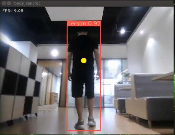
After the feature is enabled, a person stands within the camera’s field of view. When detected, the center point of the person’s body will be marked in the live feed.
Using the depth camera, the robot can sense the distance to the person in real-time and automatically adjust its position to maintain a safe and comfortable distance of approximately 3 meters. When the person approaches, the robot will move backward. When the person moves away, the robot will move forward.
7.1.10.4 Program Analysis
The program file of the feature is located at: ros2_ws/src/example/example/body_control/include/body_track.py
Note
Before modifying the program, back up the original factory code. Do not modify the source code file directly to avoid robot malfunction due to incorrect parameter changes.
Functions
Main:
def main():
    node = BodyControlNode('body_control')
    rclpy.spin(node)
    node.destroy_node()
This function starts the body tracking node.
Class
class BodyControlNode(Node):
    def __init__(self, name):
        rclpy.init()
        super().__init__(name, allow_undeclared_parameters=True, automatically_declare_parameters_from_overrides=True)
        self.name = name

        self.pid_d = pid.PID(0.1, 0, 0)
        #self.pid_d = pid.PID(0, 0, 0)

        self.pid_angular = pid.PID(0.002, 0, 0)
        #self.pid_angular = pid.PID(0, 0, 0)
        self.go_speed, self.turn_speed = 0.007, 0.04
This class represents the body tracking node.
Init:
        rclpy.init()
        super().__init__(name, allow_undeclared_parameters=True, automatically_declare_parameters_from_overrides=True)
        self.name = name

        self.pid_d = pid.PID(0.1, 0, 0)
        #self.pid_d = pid.PID(0, 0, 0)

        self.pid_angular = pid.PID(0.002, 0, 0)
        #self.pid_angular = pid.PID(0, 0, 0)

        self.go_speed, self.turn_speed = 0.007, 0.04
Initializes the parameters required for body tracking, reads the camera feed, depth data, chassis control, and YOLOv11 recognition nodes. It then synchronizes the data to align depth information with the image data, and finally, starts the main function within the class.
get_node_state:
    def get_node_state(self, request, response):
        response.success = True
        return response
Sets the current initialization state of the node.
shutdown:
    def shutdown(self, signum, frame):
        self.running = False
A callback function to terminate the recognition process upon program exit.
get_object_callback:
    def get_object_callback(self, msg):
        for i in msg.objects:
            class_name = i.class_name
            if class_name == 'person':
                if i.box[1] < 10:
                    self.center = [int((i.box[0] + i.box[2])/2), int(i.box[1]) + abs(int((i.box[1] - i.box[3])/4))]
                else:
                    self.center = [int((i.box[0] + i.box[2])/2), int(i.box[1]) + abs(int((i.box[1] - i.box[3])/3))]
This callback function from the YOLOv11 recognition node processes the recognition data and converts it into pixel coordinates.
multi_callback:
    def depth_image_callback(self, depth_image):
        self.depth_frame = np.ndarray(shape=(depth_image.height, depth_image.width), dtype=np.uint16, buffer=depth_image.data)

    def image_callback(self, ros_image):
        cv_image = self.bridge.imgmsg_to_cv2(ros_image, "rgb8")
        rgb_image = np.array(cv_image, dtype=np.uint8)
        if self.image_queue.full():
            # If the queue is full, discard the oldest image
            self.image_queue.get()
        # Put the image into the queue
        self.image_queue.put(rgb_image)
This is the callback function for time synchronization. It takes both depth and RGB data, synchronizes them, and adds them to a queue.
image_proc:
    def image_proc(self, rgb_image):
        twist = Twist()
        if self.center is not None:
            h, w = rgb_image.shape[:-1]
            cv2.circle(rgb_image, tuple(self.center), 10, (0, 255, 255), -1)
            #################
            roi_h, roi_w = 5, 5
            w_1 = self.center[0] - roi_w
            w_2 = self.center[0] + roi_w
            if w_1 < 0:
                w_1 = 0
            if w_2 > w:
                w_2 = w
A function for tracking the body. It calls the model to identify the person’s position and uses PID control to move the robot based on the person’s location.
Main:
    def main(self):
        while self.running:
            try:
                image = self.image_queue.get(block=True, timeout=1)
            except queue.Empty:
                if not self.running:
                    break
                else:
                    continue
            try:
                result_image = self.image_proc(image)
            except BaseException as e:
                result_image = image.copy()
                self.get_logger().info('\033[1;32m%s\033[0m' % e)
            self.center = None
            cv2.imshow(self.name, cv2.cvtColor(result_image, cv2.COLOR_RGB2BGR))
            key = cv2.waitKey(1)
            if key == ord('q') or key == 27:  # Press Q or Esc to exit
                self.mecanum_pub.publish(Twist())
                self.running = False
The main function within the BodyControlNode class is responsible for feeding images into the recognition function and displaying the returned frames.
7.1.10.5 Feature Extension
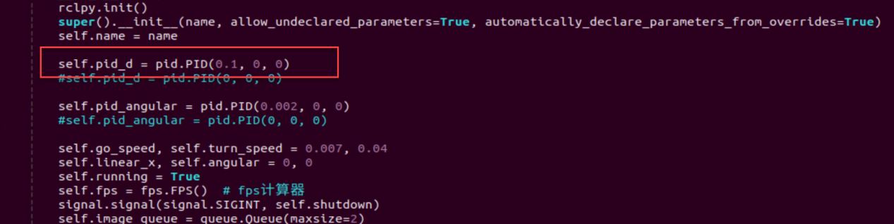
By default, the tracking speed is fixed. To modify the robot’s tracking speed, adjust the PID parameters in the program.
Open the terminal and enter the command to navigate to the directory where the program is stored.
cd ~/ros2_ws/src/example/example/body_control/include/
Then, use the command to open the program file.
vim body_track.py
Locate the
self.pid_dandself.pid_angularfunctions, where the values inside the parentheses correspond to the PID parameters. One controls the tracking linear velocity PID, and the other controls the tracking angular velocity PID.
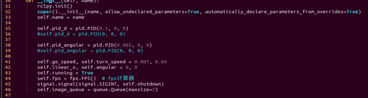
The three PID parameters—proportional, integral, and derivative—serve different purposes: the proportional adjusts the response level, the integral smooths the response, and the derivative helps control overshoot.
To adjust the tracking speed, press the i key to enter edit mode, then increase the values. For example, set the linear velocity PID to 0.05 to boost the tracking speed.
Note
It’s recommended not to increase the parameters too much, as doing so can cause the robot to track too quickly and negatively impact the feature.
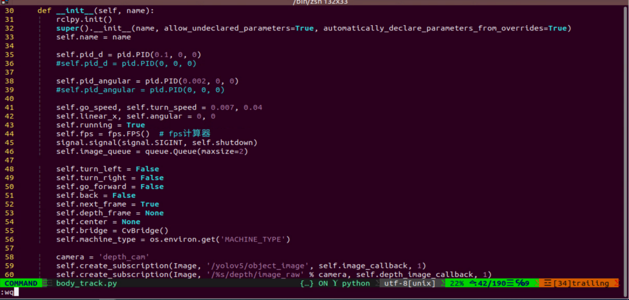
After making the changes, press Esc to exit edit mode, then type
:wqto save and exit.
Follow the steps in Section 7.1.10.2 Operation Steps to activate the feature.
7.1.11 Body Gesture Control with RGB Fusion
The depth camera is fused with RGB, allowing the system to perform both color recognition and body-gesture control. Based on the Section 7.1.9 Body Gesture Control in this document, this session incorporates color recognition to determine the control target. Only when a person wearing a specified color is detected, which can be set through color calibration, can their body gestures be used to control the robot.
If a person wearing the specified color is not detected, the robot cannot be controlled. This allows precise targeting of the person who can control the robot.
7.1.11.1 Experiment Overview
First, the MediaPipe human pose estimation model is imported, and the camera feed is accessed by subscribing to the relevant topic messages.
Next, based on the constructed model, the key points of the human torso in the camera feed are detected, and lines are drawn between the key points to visualize the torso and determine the body posture. The center of the body is calculated based on all key points.
Finally, if the detected posture is “hands on hips,” the system uses the clothing color to identify the control target, and the robot enters control mode. When the person performs specific gestures, the robot responds accordingly.
7.1.11.2 Operation Steps
Note
Commands must be entered with correct capitalization. The Tab key can be used to auto-complete keywords.
Power on the robot and connect it via the VNC remote control software. For detailed information on connecting to a remote desktop, please refer to the section 1.7.2 AP Mode Connection Steps in the user manual.
Click the terminal icon
in the system desktop to open a command-line window.Enter the command to disable the app auto-start service.
~/.stop_ros.sh
Enter the following command and press Enter to start the feature.
ros2 launch example body_and_rgb_control.launch.py
To exit this feature, press the Esc key in the image window to close the camera feed.
To exit the feature, press Ctrl+C in the terminal. If the program does not close successfully, try pressing Ctrl+C again.
7.1.11.3 Project Outcome
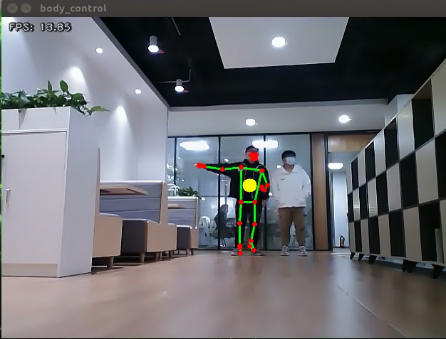
After starting the feature, stand within the camera’s field of view. When a person is detected, the camera feed will display the torso key points, lines connecting the points, and the body’s center point.
Step 1: Adjust the camera slightly higher and maintain a reasonable distance to ensure the full body is captured.
Step 2: When the person who will control the robot appears in the camera feed and strikes a hands-on-hips pose, wait for the buzzer to sound briefly. This indicates that the robot has completed the body center and clothing color calibration and is now in control mode.
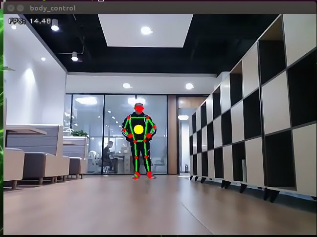
Step 3:
Left movement: Raise the right arm, and the robot will move to the left.
Right movement: Raise the left arm, and the robot will move to the right.
Forward movement: Raise the left leg, and the robot will move forward.
Backward movement: Raise the right leg, and the robot will move backward.
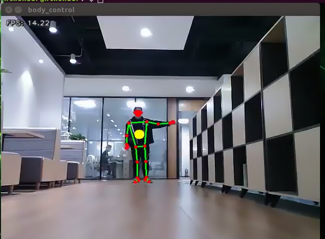
Step 4: If someone wearing a different color enters the camera’s field of view, they will not be able to control the robot.
7.1.11.4 Program Analysis
The program file of the feature is located at: ros2_ws/src/example/example/body_control/include/body_and_rgb_control.py
Note
Before modifying the program, back up the original factory code. Do not modify the source code file directly to avoid robot malfunction due to incorrect parameter changes.
Functions
Main:
def main():
    node = BodyControlNode('body_control')
    rclpy.spin(node)
    node.destroy_node()
Starts the RGB-based body gesture control node.
get_body_center:
def get_body_center(h, w, landmarks):
    landmarks = np.array([(lm.x * w, lm.y * h) for lm in landmarks])
    center = ((landmarks[LEFT_HIP] + landmarks[LEFT_SHOULDER] + landmarks[RIGHT_HIP] + landmarks[RIGHT_SHOULDER])/4).astype(int)
    return center.tolist()
Obtains the currently detected body contour.
get_joint_landmarks:
def get_joint_landmarks(img, landmarks):
    """
    Convert landmarks from medipipe's normalized output to pixel coordinates
    :param img: Picture corresponding to pixel coordinate
    :param landmarks: Normalized keypoint
    """
    h, w, _ = img.shape
    landmarks = [(lm.x * w, lm.y * h) for lm in landmarks]
    return np.array(landmarks)
Converts the detected information into pixel coordinates.
get_dif:
def get_dif(list1, list2):
    if len(list1) != len(list2):
        return 255*3
    else:
        d = np.absolute(np.array(list1) - np.array(list2))
        return sum(d)
Compares the clothing color on the detected body contour.
joint_angle:
def joint_angle(landmarks):
    """
    Calculate flex angle of each joint
    :param landmarks: Hand keypoints
    :return: Joint angle
    """
    angle_list = []
    left_hand_angle1 = vector_2d_angle(landmarks[LEFT_SHOULDER] - landmarks[LEFT_ELBOW], landmarks[LEFT_WRIST] - landmarks[LEFT_ELBOW])
    angle_list.append(int(left_hand_angle1))

    left_hand_angle2 = vector_2d_angle(landmarks[LEFT_HIP] - landmarks[LEFT_SHOULDER], landmarks[LEFT_WRIST] - landmarks[LEFT_SHOULDER])
    angle_list.append(int(left_hand_angle2))

    right_hand_angle1 = vector_2d_angle(landmarks[RIGHT_SHOULDER] - landmarks[RIGHT_ELBOW], landmarks[RIGHT_WRIST] - landmarks[RIGHT_ELBOW])
    angle_list.append(int(right_hand_angle1))

    right_hand_angle2 = vector_2d_angle(landmarks[RIGHT_HIP] - landmarks[RIGHT_SHOULDER], landmarks[RIGHT_WRIST] - landmarks[RIGHT_SHOULDER])
    angle_list.append(int(right_hand_angle2))

    return angle_list
Calculates the angles between detected body joints.
joint_distance:
def joint_distance(landmarks):
    distance_list = []

    d1 = landmarks[LEFT_HIP] - landmarks[LEFT_SHOULDER]
    d2 = landmarks[LEFT_HIP] - landmarks[LEFT_WRIST]
    dis1 = d1[0]**2 + d1[1]**2
    dis2 = d2[0]**2 + d2[1]**2
    distance_list.append(round(dis1/dis2, 1))

    d1 = landmarks[RIGHT_HIP] - landmarks[RIGHT_SHOULDER]
    d2 = landmarks[RIGHT_HIP] - landmarks[RIGHT_WRIST]
    dis1 = d1[0]**2 + d1[1]**2
    dis2 = d2[0]**2 + d2[1]**2
    distance_list.append(round(dis1/dis2, 1))

    d1 = landmarks[LEFT_HIP] - landmarks[LEFT_ANKLE]
    d2 = landmarks[LEFT_ANKLE] - landmarks[LEFT_KNEE]
    dis1 = d1[0]**2 + d1[1]**2
    dis2 = d2[0]**2 + d2[1]**2
    distance_list.append(round(dis1/dis2, 1))

    d1 = landmarks[RIGHT_HIP] - landmarks[RIGHT_ANKLE]
    d2 = landmarks[RIGHT_ANKLE] - landmarks[RIGHT_KNEE]
    dis1 = d1[0]**2 + d1[1]**2
    dis2 = d2[0]**2 + d2[1]**2
    distance_list.append(round(dis1/dis2, 1))

    return distance_list
Calculates the distances between joints based on pixel coordinates.
Class
class BodyControlNode(Node):
    def __init__(self, name):
        rclpy.init()
        super().__init__(name)
        self.name = name
        self.drawing = mp.solutions.drawing_utils
        self.body_detector = mp_pose.Pose(
            static_image_mode=False,
            min_tracking_confidence=0.7,
            min_detection_confidence=0.7)

        self.color_picker = ColorPicker(Point(), 2)
        signal.signal(signal.SIGINT, self.shutdown)
        self.fps = fps.FPS()  # FPS calculator

        self.running = True
        self.current_color = None
        self.lock_color = None
        self.calibrating = False
        self.move_finish = True
        self.stop_flag = False
        self.count_akimbo = 0
        self.count_no_akimbo = 0
        self.can_control = False
This class represents the body control node.
Init:
    def __init__(self, name):
        rclpy.init()
        super().__init__(name)
        self.name = name
        self.drawing = mp.solutions.drawing_utils
        self.body_detector = mp_pose.Pose(
            static_image_mode=False,
            min_tracking_confidence=0.7,
            min_detection_confidence=0.7)

        self.color_picker = ColorPicker(Point(), 2)
        signal.signal(signal.SIGINT, self.shutdown)
        self.fps = fps.FPS()  # FPS calculator
Initializes the parameters required for body control, subscribes to the camera image topic, initializes the servos, chassis, buzzer, motors, and finally starts the main function within the class.
get_node_state:
    def get_node_state(self, request, response):
        response.success = True
        return response
Sets the current initialization state of the node.
shutdown:
    def shutdown(self, signum, frame):
        self.running = False
A callback function to terminate the recognition process upon program exit.
image_callback:
    def image_callback(self, ros_image):
        cv_image = self.bridge.imgmsg_to_cv2(ros_image, "rgb8")
        rgb_image = np.array(cv_image, dtype=np.uint8)
        if self.image_queue.full():
            # If the queue is full, discard the oldest image
            self.image_queue.get()
        # Put the image into the queue
        self.image_queue.put(rgb_image)
Image topic callback function processes images and places them into a queue.
Move:
    def move(self, *args):
        if args[0].angular.z == -1.0:
            self.acker_turn(1900)
            time.sleep(0.2)
            motor1 = MotorState()
            motor1.id = 2
            motor1.rps = 2.0
            motor2 = MotorState()
            motor2.id = 4
            motor2.rps = -0.5
            msg = MotorsState()
            msg.data = [motor1, motor2]
            self.motor_pub.publish(msg)
            time.sleep(8.0)
            self.acker_turn(1500)
            motor1 = MotorState()
            motor1.id = 2
            motor1.rps = 0.0
            motor2 = MotorState()
            motor2.id = 4
            motor2.rps = 0.0
            msg = MotorsState()
            msg.data = [motor1, motor2]
            self.motor_pub.publish(msg)
        elif args[0].angular.z == 1.0:
            self.acker_turn(1100)
            time.sleep(0.2)
            motor1 = MotorState()
            motor1.id = 2
            motor1.rps = 0.5
            motor2 = MotorState()
            motor2.id = 4
            motor2.rps = -2.0
            msg = MotorsState()
            msg.data = [motor1, motor2]
            self.motor_pub.publish(msg)
            time.sleep(8.0)
            self.acker_turn(1500)
            motor1 = MotorState()
            motor1.id = 2
            motor1.rps = 0.0
            motor2 = MotorState()
            motor2.id = 4
            motor2.rps = 0.0
            msg = MotorsState()
            msg.data = [motor1, motor2]
            self.motor_pub.publish(msg)
        else:
            self.mecanum_pub.publish(args[0])
            time.sleep(args[1])
            self.mecanum_pub.publish(Twist())
            time.sleep(0.1)
        self.stop_flag =True
        self.move_finish = True
Motion strategy function controls the robot’s movement according to the detected body actions.
buzzer_warn:
    def buzzer_warn(self):
        msg = BuzzerState()
        msg.freq = 1900
        msg.on_time = 0.2
        msg.off_time = 0.01
        msg.repeat = 1
        self.buzzer_pub.publish(msg)
Buzzer control function, triggers buzzer alerts.
image_proc:
    def image_proc(self, image):
        image_flip = cv2.flip(cv2.cvtColor(image, cv2.COLOR_RGB2BGR), 1)
        results = self.body_detector.process(image)
        if results is not None and results.pose_landmarks is not None:
            twist = Twist()

            landmarks = get_joint_landmarks(image, results.pose_landmarks.landmark)

            # Hands-on-hips calibration
            angle_list = joint_angle(landmarks)
            #print(angle_list)
            if -150 < angle_list[0] < -90 and -30 < angle_list[1] < -10 and 90 < angle_list[2] < 150 and 10 < angle_list[3] < 30:
                self.count_akimbo += 1  # Hands-on-hips detection+1
                self.count_no_akimbo = 0  # Clear no hands-on-hips detection
            else:
                self.count_akimbo = 0  # Clear hands-on-hips detection
Body recognition function that calls the model to detect and draw key points of the human body, then performs color recognition by reading the color information from different body contours. Finally, it determines the detected color and executes corresponding movements based on the recognized body posture.
Main:
    def main(self):
        while self.running:
            try:
                image = self.image_queue.get(block=True, timeout=1)
            except queue.Empty:
                if not self.running:
                    break
                else:
                    continue
            try:
                result_image = self.image_proc(np.copy(image))
            except BaseException as e:
                self.get_logger().info('\033[1;32m%s\033[0m' % e)
                result_image = cv2.flip(cv2.cvtColor(image, cv2.COLOR_RGB2BGR), 1)
            self.fps.update()
            result_image = self.fps.show_fps(result_image)
            cv2.imshow(self.name, result_image)
            key = cv2.waitKey(1)
            if key == ord('q') or key == 27:  # Press Q or Esc to exit
                self.mecanum_pub.publish(Twist())
                self.running = False
        rclpy.shutdown()
The main function within the BodyControlNode class is responsible for feeding images into the recognition function and displaying the returned frames.
7.1.12 Human Pose Detection
In this program, a human pose estimation model from the MediaPipe machine learning framework is used to detect human poses. When the robot detects that a person has fallen, it will trigger an alert and perform a left-right twisting motion.
7.1.12.1 Experiment Overview
First, the MediaPipe human pose estimation model is imported, and the camera feed is accessed by subscribing to the relevant topic messages.
Next, the image is flipped and processed to detect human body information within the frame. Based on the connections between human keypoints, the system calculates the body height to determine body movements.
Finally, if a fall is detected, the robot will trigger an alert and move forward and backward.
7.1.12.2 Operation Steps
Note
Commands must be entered with correct capitalization. The Tab key can be used to auto-complete keywords.
Power on the robot and connect it via the VNC remote control software. For detailed information on connecting to a remote desktop, please refer to the section 1.7.2 AP Mode Connection Steps in the user manual.
Click the terminal icon
in the system desktop to open a command-line window.Enter the command to disable the app auto-start service.
~/.stop_ros.sh
Enter the following command and press Enter to start the feature.
ros2 launch example fall_down_detect.launch.py
To exit this feature, press the Esc key in the image window to close the camera feed.
To exit the feature, press Ctrl+C in the terminal. If the program does not close successfully, try pressing Ctrl+C again.
7.1.12.3 Project Outcome
After starting the feature, make sure the person is fully within the camera’s field of view. When a person is detected, the keypoints of the body will be marked on the live feed.
When the person appears with a significantly low height in the camera feed, the robot will recognize it as a falling posture and initiate an emergency response. The robot will emit a continuous alarm sound and move rapidly back and forth.
7.1.12.4 Program Analysis
The program file of the feature is located at: ros2_ws/src/example/example/body_control/include/fall_down_detect.py
Note
Before modifying the program, back up the original factory code. Do not modify the source code file directly to avoid robot malfunction due to incorrect parameter changes.
Functions
Main:
def main():
    node = FallDownDetectNode('fall_down_detect')
    rclpy.spin(node)
    node.destroy_node()
Starts the body motion control node.
get_joint_landmarks:
def get_joint_landmarks(img, landmarks):
    """
    Convert landmarks from medipipe's normalized output to pixel coordinates
    :param img: Picture corresponding to pixel coordinate
    :param landmarks: Normalized keypoint
    :return:
    """
    h, w, _ = img.shape
    landmarks = [(lm.x * w, lm.y * h) for lm in landmarks]
    return np.array(landmarks)
Converts the detected information into pixel coordinates.
height_cal:
def height_cal(landmarks):
    y = []
    for i in landmarks:
        y.append(i[1])
    height = sum(y)/len(y)

    return height
Calculates the body height based on the detected information.
Class
class FallDownDetectNode(Node):
    def __init__(self, name):
        rclpy.init()
        super().__init__(name, allow_undeclared_parameters=True, automatically_declare_parameters_from_overrides=True)
        self.name = name
        self.drawing = mp.solutions.drawing_utils
        self.body_detector = mp_pose.Pose(
            static_image_mode=False,
            min_tracking_confidence=0.7,
            min_detection_confidence=0.7)
        self.running = True
        self.fps = fps.FPS()  # FPS calculator

        self.fall_down_count = []
        self.move_finish = True
        self.stop_flag = False
        signal.signal(signal.SIGINT, self.shutdown)
        self.bridge = CvBridge()
        self.image_queue = queue.Queue(maxsize=2)
It is the fall detection node.
Init:
    def __init__(self, name):
        rclpy.init()
        super().__init__(name, allow_undeclared_parameters=True, automatically_declare_parameters_from_overrides=True)
        self.name = name
        self.drawing = mp.solutions.drawing_utils
        self.body_detector = mp_pose.Pose(
            static_image_mode=False,
            min_tracking_confidence=0.7,
            min_detection_confidence=0.7)
        self.running = True
        self.fps = fps.FPS()  # FPS calculator
Initializes the parameters required for body control, subscribes to the camera image topic, initializes the chassis, buzzer, motors, and finally starts the main function within the class.
get_node_state:
    def get_node_state(self, request, response):
        response.success = True
        return response
Sets the current initialization state of the node.
shutdown:
    def shutdown(self, signum, frame):
        self.running = False
A callback function to terminate the recognition process upon program exit.
image_callback:
    def image_callback(self, ros_image):
        cv_image = self.bridge.imgmsg_to_cv2(ros_image, "rgb8")
        rgb_image = np.array(cv_image, dtype=np.uint8)
        if self.image_queue.full():
            # If the queue is full, discard the oldest image
            self.image_queue.get()
        # Put the image into the queue
        self.image_queue.put(rgb_image)
The image topic callback function processes images and places them into a queue.
Move:
    def move(self):
        for i in range(5):
            twist = Twist()
            twist.linear.x = 0.2
            self.mecanum_pub.publish(twist)
            time.sleep(0.2)
            twist = Twist()
            twist.linear.x = -0.2
            self.mecanum_pub.publish(twist)
            time.sleep(0.2)
        self.mecanum_pub.publish(Twist())
        self.stop_flag =True
        self.move_finish = True
Motion strategy function controls the robot’s movement according to the detected body height.
buzzer_warn:
def buzzer_warn(self):
    if not self.stop_flag:
        while not self.stop_flag:
            msg = BuzzerState()
            msg.freq = 1000
            msg.on_time = 0.1
            msg.off_time = 0.1
            msg.repeat = 1
            self.buzzer_pub.publish(msg)
            time.sleep(0.2)
    else:
        msg = BuzzerState()
        msg.freq = 1900
        msg.on_time = 0.2
        msg.off_time = 0.01
        msg.repeat = 1
        self.buzzer_pub.publish(msg)
Buzzer control function triggers buzzer alerts.
image_proc:
    def image_proc(self, image):
        image_flip = cv2.flip(cv2.cvtColor(image, cv2.COLOR_RGB2BGR), 1)
        results = self.body_detector.process(image)
        if results is not None and results.pose_landmarks:
            if self.move_finish:
                landmarks = get_joint_landmarks(image, results.pose_landmarks.landmark)
                h = height_cal(landmarks)
                if h > image.shape[:-2][0] - 120:
                    self.fall_down_count.append(1)
                else:
                    self.fall_down_count.append(0)
                if len(self.fall_down_count) == 3:
                    count = sum(self.fall_down_count)
Body recognition function uses the model to draw human keypoints and performs movements according to the detected body height.
Main:
    def main(self):
        while self.running:
            try:
                image = self.image_queue.get(block=True, timeout=1)
            except queue.Empty:
                if not self.running:
                    break
                else:
                    continue
            try:
                result_image = self.image_proc(np.copy(image))
            except BaseException as e:
                self.get_logger().info('\033[1;32m%s\033[0m' % e)
                result_image = cv2.flip(cv2.cvtColor(image, cv2.COLOR_RGB2BGR), 1)
            self.fps.update()
            result_image = self.fps.show_fps(result_image)
            cv2.imshow(self.name, result_image)
            key = cv2.waitKey(1)
            if key == ord('q') or key == 27:  # Press Q or Esc to exit
                self.mecanum_pub.publish(Twist())
                self.running = False
The main function within the FallDownDetectNode class is responsible for feeding images into the recognition function and displaying the returned frames.
7.2 Machine Learning Basics
7.2.1 Introduction to Machine Learning
7.2.1.1 Overview
Artificial Intelligence (AI) is a new technological science focused on the theories, methods, technologies, and applications used to simulate, extend, and augment human intelligence.
AI encompasses various fields such as machine learning, computer vision, natural language processing, and deep learning. Among them, machine learning is a subfield of AI, and deep learning is a specific type of machine learning.
Since its inception, AI has seen rapid development in both theory and technology, with expanding application areas, gradually evolving into an independent discipline.
7.2.1.2 What Is Machine Learning
Machine Learning is the core of AI and the fundamental approach to enabling machine intelligence. It is an interdisciplinary field involving probability theory, statistics, approximation theory, convex analysis, algorithmic complexity, and more.
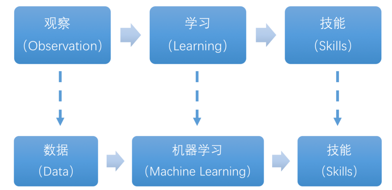
The essence of machine learning lies in enabling computers to simulate or implement human learning behaviors in order to acquire new knowledge or skills, and reorganize existing knowledge structures to continuously improve performance. From a practical perspective, machine learning involves training models using data and making predictions with those models.
Take AlphaGo as an example—it was the first AI program to defeat a professional human Go player and later a world champion. AlphaGo operates based on deep learning, which involves learning the underlying patterns and hierarchical representations from sample data to gain insights.
7.2.1.3 Types of Machine Learning
Machine learning is generally classified into supervised learning and unsupervised learning, with the key distinction being whether the dataset’s categories or patterns are known.
Supervised Learning
Supervised learning provides a dataset along with correct labels or answers. The algorithm learns to map inputs to outputs based on this labeled data. This is the most common type of machine learning.
Labeled Data: Supervised learning uses training data that includes both input features and corresponding labels or outputs. Features describe the attributes of the data, while labels represent the target variable the model is expected to predict or classify. For instance, in image recognition, a large number of images of dogs can be labeled as “dog.” The machine learns to recognize dogs in new images through this data.
Model Selection: Choosing the appropriate model to represent the relationship in the data is crucial. Common models include linear regression, logistic regression, decision trees, support vector machines (SVM), and deep neural networks. The choice depends on the data characteristics and the specific problem.
Feature Engineering: This involves preprocessing and transforming raw data to extract meaningful features. It includes data cleaning, handling missing values, normalization or standardization, feature selection, and feature transformation. Good feature engineering enhances model performance and generalization.
Training and Optimization: Using labeled training data, the model is trained to fit the underlying relationships. This typically involves defining a loss function, selecting an appropriate optimization algorithm, and iteratively adjusting model parameters to minimize the loss. Common optimization methods include gradient descent and stochastic gradient descent.
Model Evaluation: After training, the model is evaluated to assess its performance on new data. Common metrics include accuracy, precision, recall, F1-score, and ROC curves. Evaluating the model ensures it is suitable for real-world applications.
In summary, supervised learning involves using labeled training data to build a model that can classify or predict unseen data. Key steps include model selection, feature engineering, model training and optimization, and performance evaluation. Together, these steps form the foundation of supervised learning.
Unsupervised Learning
Unsupervised learning involves providing the algorithm with data without labels or known answers. All data is treated equally, and the machine is expected to uncover hidden structures or patterns.
For example, in image classification, if you provide a set of images containing cats and dogs without any labels. The algorithm will analyze the data and automatically group the images into two categories—cat images and dog images—based on similarities.
7.2.2 Introduction to Machine Learning Libraries
7.2.2.1 Common Machine Learning Frameworks
There are many machine learning frameworks available. The most commonly used include PyTorch, TensorFlow, PaddlePaddle, and MXNet.
7.2.2.2 PyTorch
Torch is an open-source machine learning framework under the BSD License, widely used for its powerful multi-dimensional array operations. PyTorch is a machine learning library based on Torch but offers greater flexibility, supports dynamic computation graphs, and provides a Python interface.
Unlike TensorFlow’s static computation graphs, PyTorch uses dynamic computation graphs, which can be modified in real-time according to the needs of the computation. PyTorch allows developers to accelerate tensor operations using GPUs, build dynamic graphs, and perform automatic differentiation.

7.2.2.3 Tensorflow
TensorFlow is an open-source machine learning framework designed to simplify the process of building, training, evaluating, and saving neural networks. It enables the implementation of machine learning and deep learning concepts in the simplest way. With its foundation in computational algebra and optimization techniques,
TensorFlow allows for efficient mathematical computations. It can run on a wide range of hardware—from supercomputers to embedded systems—making it highly versatile. TensorFlow supports CPU, GPU, or both simultaneously. Compared to other frameworks, TensorFlow is best suited for industrial deployment, making it highly appropriate for use in production environments.

7.2.2.4 PaddlePaddle
PaddlePaddle, developed by Baidu, is China’s first open-source, industrial-grade deep learning platform. It integrates a deep learning training and inference framework, a library of foundational models, end-to-end development tools, and a rich suite of supporting components. Built on years of Baidu’s R&D and real-world applications in deep learning, PaddlePaddle is powerful and versatile.
In recent years, deep learning has achieved outstanding performance across many fields such as image recognition, speech recognition, natural language processing, robotics, online advertising, medical diagnostics, and finance.
7.2.2.5 MXNet
MXNet is another high-performance deep learning framework that supports multiple programming languages, including Python, C++, Scala, and R. It offers data flow graphs similar to those in Theano and TensorFlow and supports multi-GPU configuration. It also includes high-level components for model building, comparable to those in Lasagne and Blocks, and can run on nearly any hardware platform—including mobile devices.

MXNet is designed to maximize efficiency and flexibility. As an accelerated library, it provides powerful tools for developers to take full advantage of GPUs and cloud computing. MXNet supports distributed deployment via a parameter server and can scale almost linearly across multiple CPUs and GPUs.
7.3 Machine Learning Application
7.3.1 YOLOv8 Model
7.3.1.1 Overview of the YOLO Models
YOLO Series
YOLO (You Only Look Once) is a One-stage, deep learning-based regression approach to object detection.
Before the advent of YOLOv1, the R-CNN family of algorithms dominated the object detection field. Although the R-CNN series achieved high detection accuracy, its Two-stage architecture limited its speed, making it unsuitable for real-time applications.
To address this issue, the YOLO series was developed. The core idea behind YOLO is to redefine object detection as a regression problem. It processes the entire image as input to the network and directly outputs Bounding Box coordinates along with their corresponding class labels. Compared to traditional object detection methods, YOLO offers faster detection speed and higher average precision.
YOLOv8
YOLOv8 builds upon previous versions of the YOLO model, delivering significant improvements in both detection speed and accuracy.
A typical object detection algorithm can be divided into four modules: the input module, the backbone network, the neck network, and the head output module. Analyzing YOLOv8 according to these modules reveals the following enhancements:
Input Module: During model training, YOLOv8 uses Mosaic data augmentation to improve training speed and accuracy. It also introduces adaptive anchor box calculation and adaptive image scaling.
Backbone Network: YOLOv8 incorporates the Focus and CSP structures.
Neck Network: Similar to YOLOv4, YOLOv8 adopts the FPN+PAN architecture in this part, though there are differences in implementation details.
Head Output Module: While the anchor box mechanism in YOLOv8 remains consistent with YOLOv4, improvements include the use of the GIOU_Loss loss function and DIOU_NMS for filtering predicted bounding boxes.
7.3.1.2 YOLOv8 Model Structure
Components
Convolutional Layer: Feature Extraction
Convolution is the process where an entity at multiple past time points does or is subjected to the same action, influencing its current state. Convolution can be divided into convolution and multiplication.
Convolution can be understood as flipping the data, and multiplication as the accumulation of the influence that past data has on the current data. The data flipping is done to establish relationships between data points, facilitating the calculation of accumulated influence with a proper reference.
In YOLOv8, the data to be processed are images, which are two-dimensional in computer vision. Accordingly, the convolution is a two-dimensional convolution. The purpose of 2D convolution is to extract features from images. To perform a 2D convolution, it is necessary to understand the convolution kernel.
The convolution kernel is the unit region over which the convolution calculation is performed each time. The unit is pixels, and the convolution sums the pixel values within the region. Typically, convolution is done by sliding the kernel across the image, and the kernel size is manually set.
When performing convolution, depending on the desired effect, the image borders may be padded with zeros or extended by a certain number of pixels, then the convolution results are placed back into the corresponding positions in the image. For example, a 6×6 image is first expanded to 7×7, then convolved with the kernel, and finally the results are filled back into a blank 6×6 image.
Pooling Layer: Feature Amplification
The pooling layer, also called the downsampling layer, is usually used together with convolution layers. After convolution, pooling performs further sampling on the extracted features. Pooling includes various types such as global pooling, average pooling, max pooling, etc., each producing different effects.
To make it easier to understand, max pooling is used here as an example. Before understanding max pooling, it is important to know about the filter, which is like the convolution kernel—a manually set region that slides over the image and selects pixels within the area.
Max pooling keeps the most prominent features and discards others. For example, starting with a 6×6 image, applying a 2×2 filter for max pooling produces a new image with reduced size.
Upsampling Layer: Restoring Image Size
Upsampling can be understood as reverse pooling. After pooling, the image size shrinks, and upsampling restores the image to its original size. However, only the size is restored, the pooled features are also modified accordingly.
For example, starting with a 6×6 image, applying a 3×3 filter for upsampling produces a new image.
Batch Normalization Layer: Data Regularization
Batch normalization means rearranging the data neatly, which reduces the computational difficulty of the model and helps map data better into the activation functions.
Batch normalization reduces the loss rate of features during each calculation, retaining more features for the next computation. After multiple computations, the model’s sensitivity to the data increases.
ReLU Layer: Activation Function
Activation functions are added during model construction to introduce non-linearity. Without activation functions, each layer is essentially a matrix multiplication. Every layer’s output is a linear function of the previous layer’s input, so no matter how many layers the neural network has, the output is just a linear combination of the input. This prevents the model from adapting to actual situations.
There are many activation functions, commonly ReLU, Tanh, Sigmoid, etc. Here, ReLU is used as an example. ReLU is a piecewise function that replaces all values less than 0 with 0 and keeps positive values unchanged.
ADD Layer: Tensor Addition
Features can be significant or insignificant. The ADD layer adds feature tensors together to enhance the significant features.
Concat Layer: Tensor Concatenation
The Concat layer concatenates feature tensors to combine features extracted by different methods, thereby preserving more features.
Composite Elements
When building a model, using only the basic layers mentioned earlier can lead to overly lengthy, disorganized code with unclear hierarchy. To improve modeling efficiency, these basic elements are often grouped into modular units for reuse.
Convolutional Block
A convolutional block consists of a convolutional layer, a batch normalization layer, and an activation function. The process follows this order: convolution → batch normalization → activation.
Strided Sampling and Concatenation Unit(Focus)
The input image is first divided into multiple large regions. Then, small image patches located at the same relative position within each large region are concatenated together to form a new image. This effectively splits the input image into several smaller images. Finally, an initial sampling is performed on the images using a convolutional block.
As shown in the figure below, for a 6×6 image, if each large region is defined as 2×2, the image can be divided into 9 large regions, and each contains 4 small patches.
By taking the small patches at position 1 from each large region and concatenating them, a 3×3 image can be formed. The patches at other positions are concatenated in the same way.
Ultimately, the original 6×6 image is decomposed into four 3×3 images.
Residual Block
The residual block enables the model to learn subtle variations in the image. Its structure is relatively simple and involves merging data from two paths.
In the first path, two convolutional blocks are used to extract features from the image. In the second path, the original image is passed through directly without convolution. Finally, the outputs from both paths are added together to enhance learning.
Composite Convolutional Block
In YOLOv8, a key feature of the composite convolutional block is its customizable design, allowing convolutional blocks to be configured as needed. This structure also uses two paths whose outputs are merged.
The first path contains a single convolutional layer for feature extraction, while the second path includes 2𝑥+1 convolutional blocks followed by an additional convolutional layer. After sampling and concatenation, batch normalization is applied to standardize the data, followed by an activation function. Finally, a convolutional block is used to process the combined features.
Composite Residual Convolutional Block
The composite residual convolutional block modifies the composite convolutional block by replacing the 2𝑥 convolutional blocks with 𝑥 residual blocks. In YOLOv8, this block is also customizable, allowing residual blocks to be tailored according to specific requirements.
Composite Pooling Block
The output from a convolutional block is simultaneously passed through three separate max pooling layers, while an additional unprocessed copy is preserved. The resulting four feature maps are then concatenated and passed through a convolutional block. By processing data with the composite pooling block, the original features can be significantly enhanced and emphasized.
7.3.2 YOLOv8 Workflow
This section explains the model’s processing flow using the concepts of prior boxes, prediction boxes, and anchor boxes involved in YOLOv8.
7.3.2.1 Prior Box
When an image is fed into the model, predefined regions of interest must be specified. These regions are marked using prior boxes, which serve as initial bounding box templates indicating potential object locations in the image.
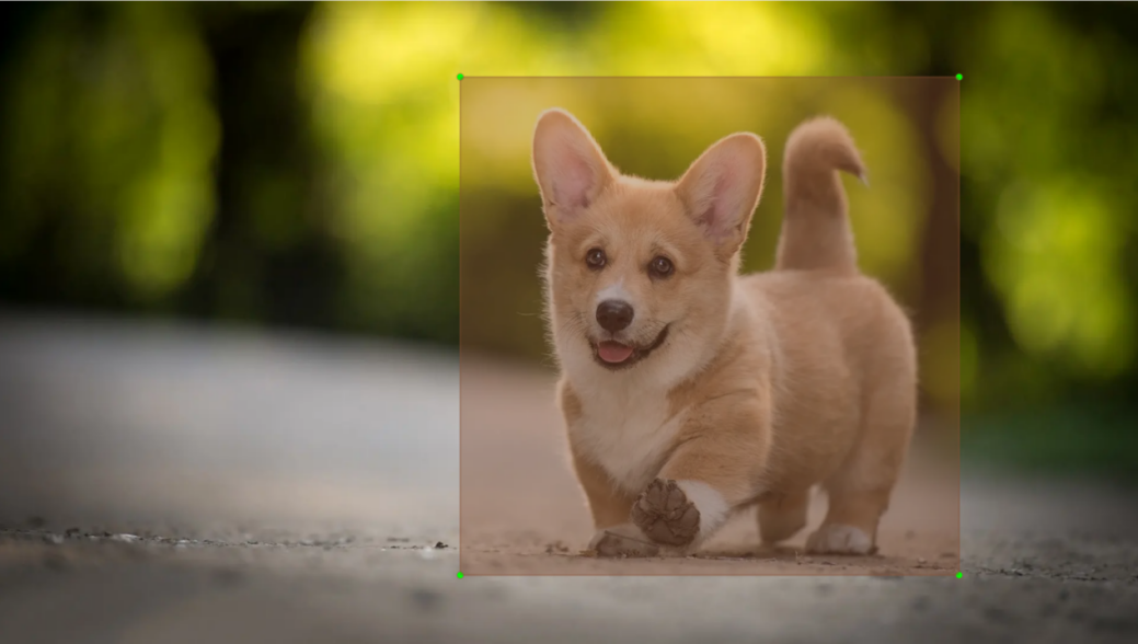
7.3.2.2 Prediction Box
Prediction boxes are generated by the model as output and do not require manual input. When the first batch of training data is fed into the model, the prediction boxes are automatically created. The center points of prediction boxes tend to be located in areas where similar objects frequently appear.
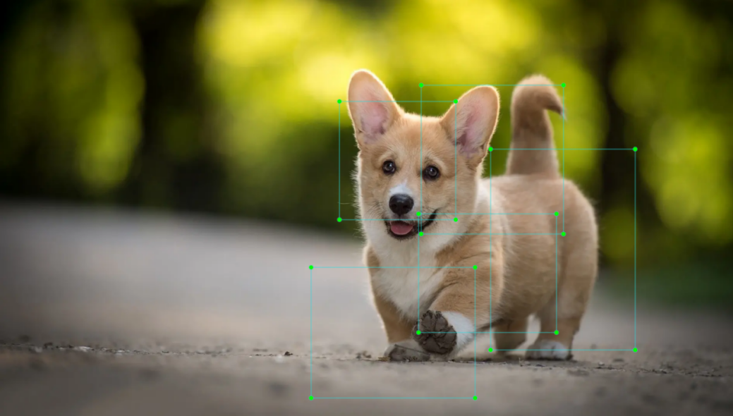
7.3.2.3 Anchor Box
Since predicted boxes may have deviations in size and location, anchor boxes are introduced to correct these predictions.
Anchor boxes are positioned based on the predicted boxes. By influencing the generation of subsequent predicted boxes, anchor boxes are placed around their relative centers to guide future predictions.
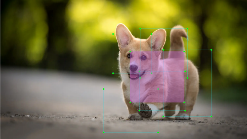
7.3.2.4 Project Process
Once the bounding box annotations are complete, prior boxes appear on the image. When the image data is input into the model, predicted boxes are generated based on the locations of the prior boxes. Subsequently, anchor boxes are generated to adjust the predicted results. The weights from this round of training are then updated in the model.
With each new training iteration, the predicted boxes are influenced by the anchor boxes from the previous round. This process is repeated until the predicted boxes gradually align with the prior boxes in both size and location.

7.3.3 Image Collection and Annotation
Training the YOLOv8 model requires a large amount of data, so data collection and annotation must be performed first to prepare for model training.
In this example, the demonstration uses traffic signs as target objects.
7.3.3.1 Image Collection
Power on the robot and connect it to a remote control tool like VNC.
Click the terminal icon
 in the system desktop to open a command-line window.
Stop the app auto-start service by entering the following command:
~/.stop_ros.sh
Start the depth camera service with the command.
ros2 launch peripherals depth_camera.launch.py
Open a new command-line terminal and enter the command to create a directory for storing your dataset.
mkdir -p ~/my_data
Then, launch the tool by entering the following command.
cd ~/software/collect_picture && python3 main.py
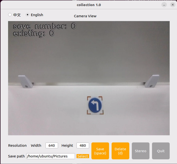
The save number in the top-left corner of the tool interface shows the ID of the saved image. The existing shows how many images have already been saved.
Click Choose to change the save path to the my_data folder created before.

After selecting the target directory, click Choose.
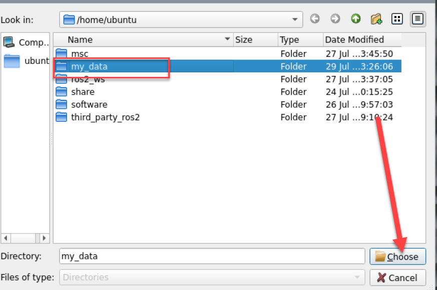
Place the target object within the camera view and click the Save(space) button or press the spacebar to save the current camera frame.
After clicking Save (space), a folder named JPEGImages will be automatically created under the path /home/ubuntu/my_data to store the images.
Note
To improve model reliability, capture the target object from various distances, angles, and tilts.
After collecting images, click the Quit button to close the tool.

Then press Ctrl+C in all opened terminal windows to exit—this completes the image collection process.
7.3.3.2 Image Annotation
Once the images are collected, they need to be annotated. Annotation is essential for creating a functional dataset, as it tells the training model which parts of the image correspond to which categories. This allows the model to later identify those categories in new, unseen images.
Note
Commands must be entered with correct capitalization. The Tab key can be used to auto-complete keywords.
Open a terminal and enter the command to start the image annotation tool:
python3 ~/software/labelImg/labelImg.py
Below is a table of common shortcut keys:
| Icon | Shortcut Key | Function |
|---|---|---|
 |
Ctrl+U | Choose the directory for images. |
 |
Ctrl+R | Choose the directory for calibration data. |
 |
W | Create an annotation box. |
 |
Ctrl+S | Save the annotation. |
 |
A | Switch to the previous image. |
 |
D | Switch to the next image. |
Click the button
 to open the image capture directory and navigate to /home/ubuntu/my_data/JPEGImages.
Then, click Choose to open the folder.
Then click the Change Save Dir button
 and select the annotation save folder, which is the Annotations directory located under the same path as the image collection.
Click Open to return to the annotation interface.
Press the W key to begin creating a bounding box.
Move the mouse to the desired location and hold the left mouse button to draw a box that covers the entire object. Release the left mouse button to finish drawing the box.
In the pop-up window, name the category of the object, e.g., left. After naming, click OK or press Enter to save the label.
Press Ctrl+S to save the annotation for the current image.
Press the D key to move to the next image, then repeat steps 7 to 9 to complete all annotations. Click the close button at the top-right corner of the tool to exit.
Open a new terminal and enter the following command to view the annotation files:
cd my_data/Annotations && ls
7.3.4 Data Format Conversion
7.3.4.1 Preparation
Before starting the operations in this section, image collection and annotation must be completed first. For detailed steps, refer to Section 7.3.3 Image Collection and Annotation.
Before training the YOLOv8 model with the data, the images need to be assigned categories, and the annotation data must be converted into the proper format.
7.3.4.2 Format Conversion
Before starting the operations in this section, image collection and annotation must be completed first.
Note
Commands must be entered with correct capitalization. The Tab key can be used to auto-complete keywords.
Open a new terminal and enter the following command to open the file:
vim ~/my_data/classes.names
Press the i key, and enter the annotated class name left in the file. If there are multiple categories, each one should be listed on a new line.
After editing, press Esc, type the command
:wq, and press Enter to save and exit.
Note
The class names here must match the labels used in the labelImg annotation tool exactly.
Next, return to the terminal and run the following command to convert the annotation format:
python3 ~/software/xml2yolo.py --data ~/my_data --yaml ~/my_data/data.yaml
Note
Make sure the paths to ~/software/xml2yolo.py and my_data match your actual file structure!
This command uses three main parameters:
xml2yolo.py: A script that converts annotations from XML format to the YOLOv8 format. Make sure the path is correct.
my_data: The directory containing the annotated dataset. Make sure the path is correct.
data.yaml: Indicates the format conversion for the entire folder after the model has been split. From the command, it is clear that the saved directory is within the my_data folder.
The following image shows a generated example of data.yaml:

The items listed after the names represent the types of labels. The nc field specifies the total number of label categories. The train refers to the training set—a commonly used term in deep learning that indicates the data used for model training. The parameter following it is the path to the training images. Similarly, the val refers to the validation set, which is used to verify the model’s performance during the training process, and the path that follows indicates where the validation data is located. These file paths need to be set based on the actual location of your data. For example, to speed up the training process later by moving the dataset from the robot to a local PC or a cloud server, the train and val paths should be updated accordingly to reflect their new locations.
Finally, an XML file will be generated under the ~/my_data folder to record the path location of the currently split dataset. Similarly, the last parameter in step 4, ~/my_data/data.yaml, can be changed to modify the save path. This file path must be remembered, as it will be used later for model training.
7.3.5 Model Training
Note
Commands must be entered with correct capitalization. The Tab key can be used to auto-complete keywords.
7.3.5.1 Preparation
After the model format conversion is complete, proceed to the model training stage. Before training, ensure that the dataset has already been converted to the required format. For details, refer to Section 7.3.4 Data Format Conversion.
7.3.5.2 Training Process
Power on the robot and connect it to a remote control tool like VNC.
Click the terminal icon
in the system desktop to open a command-line window.Enter the following command and press Enter to go to the specific directory.
cd /home/ubuntu/third_party_ros2/yolo/yolov8
Enter the command to start training the model.
python3 train.py --img 640 --batch 64 --epochs 300 --data ~/my_data/data.yaml --weights yolov8n.pt
In the command, the parameters stands for:
–img: image size.
–batch: number of images per batch.
–epochs: number of training iterations.
–data: path to the dataset.
–weights: path to the pre-trained model.
The above parameters can be adjusted according to the specific setup. To improve model accuracy, consider increasing the number of training epochs. Note that this will also increase training time.
If the following content appears, it indicates that the training is in progress.
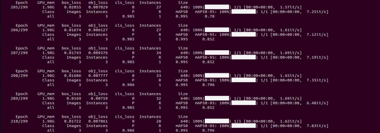
After training is complete, the terminal displays the output file path. In this example, the training results are saved in the runs/detect/train/weights directory under the yolov8 folder.
Note
The generated folder name under runs/train/ may vary. Please locate it accordingly.
7.3.6 Traffic Sign Model Training
Note
The product names and reference paths mentioned in this document may vary. Please refer to the actual setup for accurate information.
When dealing with large datasets, it is not recommended to train models directly on the robot’s onboard motherboard due to I/O speed and memory limitations. Instead, it is advised to use a PC with a dedicated GPU, which follows the same training steps, only requiring proper environment configuration.
If the traffic sign recognition performance in autonomous driving feature is unsatisfactory, training a custom model can be done by following the procedures in this section.
In the following instructions, screenshots may show different robot hostnames, as different robots have similar environment setups. Simply follow the command steps in the document as described — it does not affect the execution.
7.3.6.1 Preparation
Prepare a laptop, or if using a desktop, make sure to have a wireless network card, mouse, and other necessary tools.
Use the previously learned method to install and open the remote control tool VNC.
7.3.6.2 Operation Steps
7.3.6.3 Image Collection
Power on the robot and connect it to a remote control tool like VNC.
Click the terminal icon
in the system desktop to open a command-line window.Execute the following command to stop the app auto-start service:
~/.stop_ros.sh
Enter the following command to create a new directory for storing the dataset:
mkdir -p ~/my_data
Execute the following command to start the camera service:
ros2 launch peripherals depth_camera.launch.py
Open a new terminal, navigate to the image collection tool directory, and run the image collection script:
cd software/collect_picture && python3 main.py
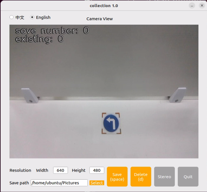
The save number in the top-left corner of the tool interface shows the ID of the saved image. The existing shows how many images have already been saved.
Change the save path to /home/ubuntu/my_data, which will also be used in later steps.

Place the target object within the camera’s view. Press the Save(space) button or the spacebar to save the current camera frame. After pressing it, both the save number and the existing counters will increase by 1. This helps track the current image ID and total image count in the folder.
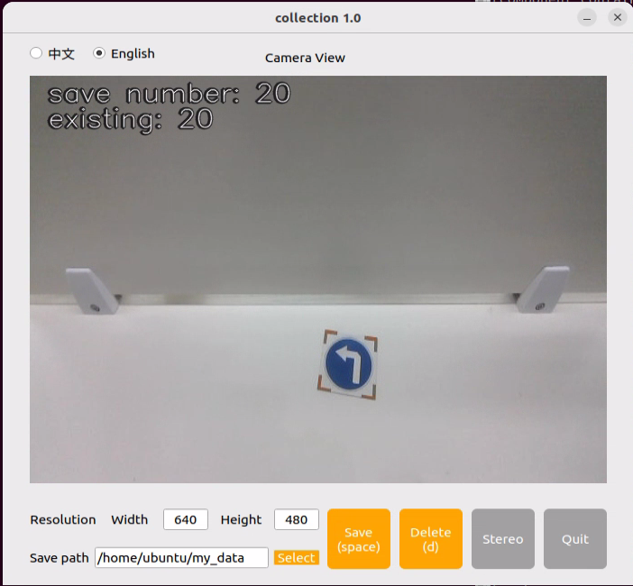
After clicking Save (space), a folder named JPEGImages will be automatically created under the path /home/ubuntu/my_data to store the images.
Note
To improve model reliability, capture the target object from various distances, angles, and tilts.
To ensure stable recognition, collect at least 200 images per category during the data collection phase.
After collecting images, click the Quit button to close the tool.

7.3.6.4 Image Annotation
Note
Commands must be entered with correct capitalization. The Tab key can be used to auto-complete keywords.
Power on the robot and connect it to a remote control tool like VNC.
Click the terminal icon
in the system desktop to open a command-line window.Execute the following command to stop the app service:
~/.stop_ros.sh
Open a new terminal and enter the following command.
python3 software/labelImg/labelImg.py
After opening the image annotation tool. Below is a table of common shortcut keys:
| Function | Shortcut Key | Function |
|---|---|---|
|
Ctrl+U | Choose the directory for images. |
|
Ctrl+R | Choose the directory for calibration data. |
|
W | Create an annotation box. |
|
Ctrl+S | Save the annotation. |
|
A | Switch to the previous image. |
|
D | Switch to the next image. |
Use the shortcut Ctrl+U, set the image storage directory to /home/ubuntu/my_data/JPEGImages/, and click Choose.
Use the shortcut Ctrl+R, set the annotation data storage directory to /home/ubuntu/my_data/Annotations/, and click Choose. The Annotations folder will be automatically generated when collecting images.
Press the W key to begin creating a bounding box.
Move the mouse to the desired location and hold the left mouse button to draw a box that covers the entire object. Release the left mouse button to finish drawing the box.
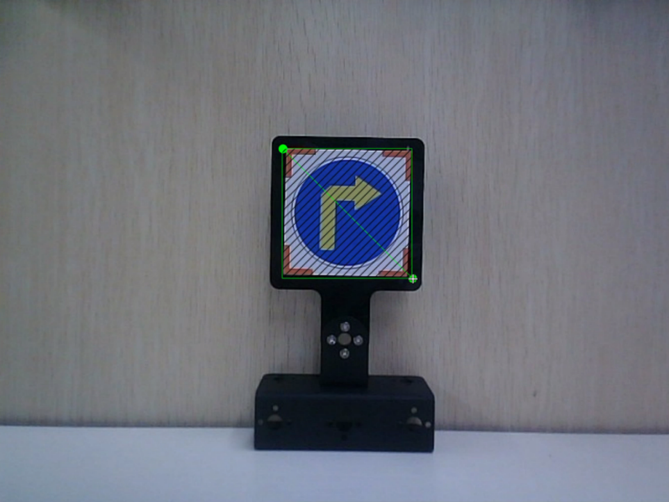
In the pop-up window, name the category of the object, e.g., right. After naming, click OK or press Enter to save the label.
Press Ctrl+S to save the annotation for the current image.
Refer to Step 9 to complete the annotation of the remaining images.
7.3.6.5 Generating Related Files
Click the terminal icon
in the system desktop to open a command-line window.Enter the following command to open the file for editing:
vim ~/my_data/classes.names
Press the i key to enter edit mode and add the class names for the target recognition objects. When adding multiple class names, each class name should be listed on a separate line.
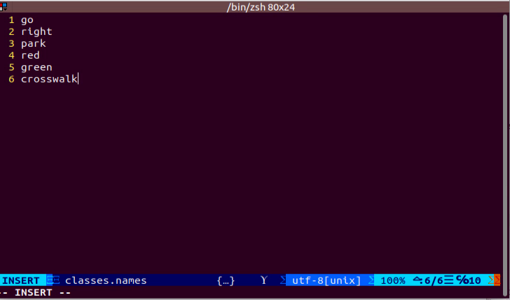
Note
The class names here must match the labels used in the labelImg annotation tool exactly.
After editing, press Esc, then type
:wqto save and close the file.
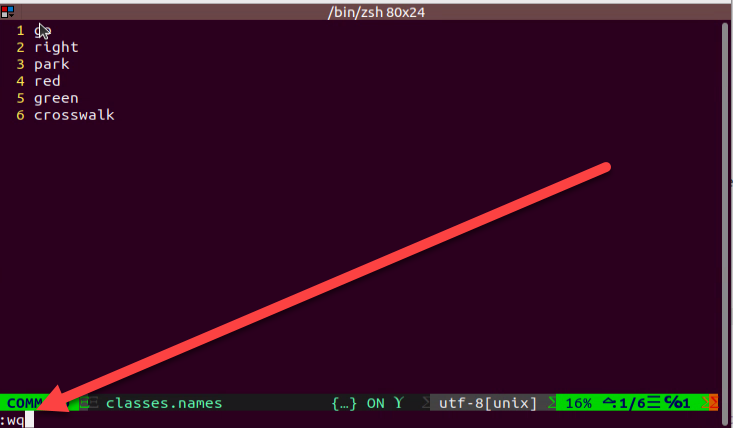
Next, enter the command to convert the data format and press Enter:
python3 ~/software/xml2yolo.py --data ~/my_data --yaml ~/my_data/data.yaml
In this command, the xml2yolo.py file is used to convert the annotated files into XML format and categorize the dataset into training and validation sets.
The output paths depend on the actual storage location of the folders in your robot’s file system. Paths may vary across devices, but the generated data.yaml file will correspond to your annotated dataset.
7.3.6.6 Training Process
Click the terminal icon
in the system desktop to open a command-line window.Then enter the command to navigate to the specific directory.
cd /home/ubuntu/third_party_ros2/yolo/yolov8
Enter the command to start training the model.
python3 train.py --img 640 --batch 64 --epochs 300 --data ~/my_data/data.yaml --weights yolov8n.pt
In the command, –img specifies the image size, –batch indicates the number of images input per batch, –epochs refers to the number of training iterations, representing how many times the machine learning model will go through the dataset. This value should be optimized based on the actual performance of the final model. In this example, the number of training epochs is set to 8 for quick testing. If the computer system is more powerful, this value can be increased to achieve better training results. –data is the path to the dataset, which refers to the folder containing the manually annotated data. –weights indicates the path to the pre-trained model weights. This specifies which .pt weight file the training process is based on. It’s important to note whether Yolov8n.pt, Yolov8s.pt, or another version is used.
The above parameters can be adjusted according to the specific setup. To improve model accuracy, consider increasing the number of training epochs. Note that this will also increase training time.
When the following options appear as shown in the image, enter 3 and press Enter.

If the following content appears, it indicates that the training is in progress.
7.3.6.7 Using the Model
Enter the following command and press Enter to stop the app service:
~/.stop_ros.sh
Enter the following command to navigate to the directory where the corresponding feature’s program is located:
cd /home/ubuntu/third_party_ros2/yolo/yolov8
Enter the command to view the models in the current directory. Pretrained models are already provided, as shown below.
The content in the red box, where best_traffic.pt is the trained best.pt model. Other trained models can be added to this directory as needed.
ls
Next, enter the command to check the program that calls the model, and manually modify the model name.
vim ~/ros2_ws/src/yolov8_detect/yolov8_detect/yolov8_detect_demo.py
Change
MODEL_DEFAULT_NAMEtobest_traffic, and then type:wqto save and exit.

After that, enter the command to run the model-calling program. A depth camera needs to be connected.
ros2 launch yolov8_detect yolov8_detect_demo.launch.py
7.4 Autonomous Driving
Before starting, it’s important to familiarize yourself with the map and the placement of relevant props.
The map should be laid on a flat surface, ensuring it is smooth without wrinkles, and that the road is clear of any obstacles. All road signs and traffic lights must be placed at the designated positions on the map, facing clockwise along the route. The positions of the road signs and the starting point are shown in the figure below.
7.4.1 Lane Keeping
This lesson focuses on controlling the car to move forward while keeping it within the lane.
7.4.1.1 Preparation
When performing this feature, make sure the environment is well-lit, but avoid direct light hitting the camera to prevent misrecognition.
Adjust the color thresholds in advance to correctly detect the yellow lines, preventing misdetection during the lesson. For guidance on setting color thresholds, refer to the course 6. ROS+OpenCV Course.
It is recommended to position the robot in the center of the lane for easier detection.
7.4.1.2. Working Principle
Lane keeping can be divided into three main parts: capturing real-time images, image processing, and result comparison.
First, real-time images are captured using the camera.
Next, the images are processed. This includes color detection, converting the detected images into a suitable color space, applying erosion and dilation, and performing binarization.
Finally, the processed images are analyzed. The region of interest (ROI) is extracted, contours are identified, and comparisons are made to determine the car’s position relative to the lane.
Based on the comparison results, the forward direction is adjusted to keep the robot centered in the lane.
7.4.1.3 Operation Steps
Power on the robot and connect it to a remote control tool like VNC. For detailed information on connecting to a remote desktop, please refer to the section 1.7.2 AP Mode Connection Steps in the user manual.
Click the terminal icon
 in the system desktop to open a command-line window.
Enter the following command and press Enter to stop the app auto-start service.
~/.stop_ros.sh
In the terminal, enter the following command and press Enter:
ros2 launch example self_driving.launch.py only_line_follow:=true
To close the program, select the corresponding terminal window and press Ctrl+C.

7.4.1.4 Program Outcome
After starting the feature, place the robot on the road of the map. The robot will detect the yellow lane markings at the edges of the road, adjust its position, and maintain itself in the center of the lane.
7.4.1.5 Program Analysis
The source code for the program is located at: ros2_ws/src/example/example/self_driving/lane_detect.py
Functions
image_callback:
def image_callback(ros_image):
    cv_image = bridge.imgmsg_to_cv2(ros_image, "bgr8")
    bgr_image = np.array(cv_image, dtype=np.uint8)
    if image_queue.full():
        # If the queue is full, remove the oldest image
        image_queue.get()
        # Put the image into the queue
    image_queue.put(bgr_image)
Image callback function used to read data from the camera node.
Class:
LaneDetector:
class LaneDetector(object):
    def __init__(self, color):
        # Lane color
        self.target_color = color
        # ROI for lane detection
        self.rois = ((340, 400, 0, 320, 0.7), (290, 310, 0, 320, 0.2), (230, 260, 0, 320, 0.1))
        self.weight_sum = 1.0

    def set_roi(self, roi):
        self.rois = roi
Init:
    def __init__(self, color):
        # Lane color
        self.target_color = color
        # ROI for lane detection
        self.rois = ((340, 400, 0, 320, 0.7), (290, 310, 0, 320, 0.2), (230, 260, 0, 320, 0.1))
        self.weight_sum = 1.0
Initializes required parameters and sets the ROI for detection.
set_roi:
    def set_roi(self, roi):
        self.rois = roi
Sets the region of interest (ROI) for detection.
get_area_max_contour:
    def get_area_max_contour(contours, threshold=100):
        '''
        Obtain the contour corresponding to the maximum area
        :param contours:
        :param threshold:
        :return:
        '''
        contour_area = zip(contours, tuple(map(lambda c: math.fabs(cv2.contourArea(c)), contours)))
        contour_area = tuple(filter(lambda c_a: c_a[1] > threshold, contour_area))
        if len(contour_area) > 0:
            max_c_a = max(contour_area, key=lambda c_a: c_a[1])
            return max_c_a
        return None
Retrieves the largest contour from a list of contours obtained via OpenCV.
add_horizontal_line:
    def add_horizontal_line(self, image):
        #   |____  --->   |————   ---> ——
        h, w = image.shape[:2]
        roi_w_min = int(w/2)
        roi_w_max = w
        roi_h_min = 0
        roi_h_max = h
        roi = image[roi_h_min:roi_h_max, roi_w_min:roi_w_max]  # Crop the right half
        flip_binary = cv2.flip(roi, 0)  # Flip upside down
        max_y = cv2.minMaxLoc(flip_binary)[-1][1]  # Extract the coordinates of the top-left point with a value of 255

        return h - max_y
Adds horizontal lines for detection based on the image width, height, and ROI.
add_vertical_line_far:
    def add_vertical_line_far(self, image):
        h, w = image.shape[:2]
        roi_w_min = int(w/8)
        roi_w_max = int(w/2)
        roi_h_min = 0
        roi_h_max = h
        roi = image[roi_h_min:roi_h_max, roi_w_min:roi_w_max]
        flip_binary = cv2.flip(roi, -1)  # Flip the image horizontally and vertically
        #cv2.imshow('1', flip_binary)
        # min_val, max_val, min_loc, max_loc = cv2.minMaxLoc(ret)
        # minVal:The minimum value
        # maxVal:The maximum value
        # minLoc:The location of the minimum value
        # maxLoc:The location of the maximum value
        # The order of traversal is: first rows, then columns, with rows from left to right and columns from top to bottom
        (x_0, y_0) = cv2.minMaxLoc(flip_binary)[-1]  # Extract the coordinates of the top-left point with a value of 255
        y_center = y_0 + 55
        roi = flip_binary[y_center:, :]
        (x_1, y_1) = cv2.minMaxLoc(roi)[-1]
        down_p = (roi_w_max - x_1, roi_h_max - (y_1 + y_center))

        y_center = y_0 + 65
        roi = flip_binary[y_center:, :]
        (x_2, y_2) = cv2.minMaxLoc(roi)[-1]
        up_p = (roi_w_max - x_2, roi_h_max - (y_2 + y_center))

        up_point = (0, 0)
        down_point = (0, 0)
        if up_p[1] - down_p[1] != 0 and up_p[0] - down_p[0] != 0:
            up_point = (int(-down_p[1]/((up_p[1] - down_p[1])/(up_p[0] - down_p[0])) + down_p[0]), 0)
            down_point = (int((h - down_p[1])/((up_p[1] - down_p[1])/(up_p[0] - down_p[0])) + down_p[0]), h)

        return up_point, down_point
Adds vertical detection lines in the far area of the image based on the ROI.
get_binary:
    def get_binary(self, image):
        # Recognize color through LAB space
        img_lab = cv2.cvtColor(image, cv2.COLOR_RGB2LAB)  # Convert RGB to LAB
        img_blur = cv2.GaussianBlur(img_lab, (3, 3), 3)  # Gaussian blur denoising
        mask = cv2.inRange(img_blur, tuple(lab_data['lab']['Stereo'][self.target_color]['min']), tuple(lab_data['lab']['Stereo'][self.target_color]['max']))  # Binarization
        eroded = cv2.erode(mask, cv2.getStructuringElement(cv2.MORPH_RECT, (3, 3)))  # Erode
        dilated = cv2.dilate(eroded, cv2.getStructuringElement(cv2.MORPH_RECT, (3, 3)))  # Dilate

        return dilated
Performs color recognition in the specified color space and generates a binary image.
add_vertical_line_near:
    def add_vertical_line_near(self, image):
        # ——|         |——        |
        #   |   --->  |     --->
        h, w = image.shape[:2]
        roi_w_min = 0
        roi_w_max = int(w/2)
        roi_h_min = int(h/5)
        roi_h_max = h
        roi = image[roi_h_min:roi_h_max, roi_w_min:roi_w_max]
        flip_binary = cv2.flip(roi, -1)  # Flip the image horizontally and vertically
        #cv2.imshow('1', flip_binary)
        (x_0, y_0) = cv2.minMaxLoc(flip_binary)[-1]  # Extract the coordinates of the top-left point with a value of 255
        down_p = (roi_w_max - x_0, roi_h_max - y_0)

        (x_1, y_1) = cv2.minMaxLoc(roi)[-1]
        y_center = int((roi_h_max - roi_h_min - y_1 + y_0)/2)
        roi = flip_binary[y_center:, :]
        (x, y) = cv2.minMaxLoc(roi)[-1]
        up_p = (roi_w_max - x, roi_h_max - (y + y_center))

        up_point = (0, 0)
        down_point = (0, 0)
        if up_p[1] - down_p[1] != 0 and up_p[0] - down_p[0] != 0:
            up_point = (int(-down_p[1]/((up_p[1] - down_p[1])/(up_p[0] - down_p[0])) + down_p[0]), 0)
            down_point = down_p

        return up_point, down_point, y_center
Adds vertical detection lines in the near area of the image based on ROI and image dimensions.
_call_:
    def __call__(self, image, result_image):
        # Extract line center based on weighted proportion
        centroid_sum = 0
        h, w = image.shape[:2]
        max_center_x = -1
        center_x = []
        max_area = 0
        min_area = h*w
        f = max_area/min_area
        for roi in self.rois:
            blob = image[roi[0]:roi[1], roi[2]:roi[3]]  # Crop ROI
            contours = cv2.findContours(blob, cv2.RETR_EXTERNAL, cv2.CHAIN_APPROX_TC89_L1)[-2]  # Find contours
            max_contour_area = self.get_area_max_contour(contours, 30)  # Obtain the contour with the largest area
            if max_contour_area is not None:
                rect = cv2.minAreaRect(max_contour_area[0])  # The minimum bounding rectangle
                box = np.intp(cv2.boxPoints(rect))  # Four box points
                area = rect[1][0]*rect[1][1]
                if area > max_area:
                    max_area = area
                if area < min_area:
                    min_area = area
                f = max_area/min_area
                for j in range(4):
                    box[j, 1] = box[j, 1] + roi[0]
                cv2.drawContours(result_image, [box], -1, (int(255*roi[-1]), 255, 0), 2)  # Draw the rectangle composed of the four points

                # Obtain the diagonal points of the rectangle
                pt1_x, pt1_y = box[0, 0], box[0, 1]
                pt3_x, pt3_y = box[2, 0], box[2, 1]
                # The center point of the line
                line_center_x, line_center_y = (pt1_x + pt3_x) / 2, (pt1_y + pt3_y) / 2

                cv2.circle(result_image, (int(line_center_x), int(line_center_y)), 5, (0, 0, 255), -1)  # Draw the center point
                center_x.append(line_center_x)
            else:
                center_x.append(-1)
        for i in range(len(center_x)):
            if center_x[i] != -1:
                if center_x[i] > max_center_x:
                    max_center_x = center_x[i]
                centroid_sum += center_x[i] * self.rois[i][-1]
        if centroid_sum == 0:
            return result_image, None, max_center_x, max_area
        center_pos = centroid_sum / self.weight_sum  # Calculate the center point based on the weight
        angle = math.degrees(-math.atan((center_pos - (w / 2.0)) / (h / 2.0)))

        return result_image, angle, max_center_x, max_area
The class’s callback function performs color recognition, draws detected yellow lines using OpenCV, and outputs the processed image, the line angles, and the pixel coordinates (X) of each ROI contour.
7.4.2 Traffic Sign Detection
This lesson focuses on recognizing traffic signs through programmed commands.
7.4.2.1 Preparation
The traffic sign model in this section is a YOLOv8 trained model. For more details on YOLOv8, please refer to the previous sections.
When performing this feature, make sure the environment is well-lit, but avoid direct light hitting the camera to prevent misrecognition.
7.4.2.2 Working Principle
First, capture the real-time video from the camera and perform image processing operations such as erosion and dilation.
Next, use YOLOv8 to run the model and compare the processed image with the target objects.
Finally, based on the comparison results, execute the corresponding traffic sign actions.
7.4.2.3 Operation Steps
Note
Note: The following steps only enable turn sign detection in the camera feed and will not trigger the corresponding robot actions. To directly experience the autonomous driving feature, skip this lesson and refer to section 7.4.6 Comprehensive Application of Autonomous Driving in this document.
The input command should be case sensitive, and the keywords can be complemented by the Tab key.
Power on the robot and connect it to a remote control tool like VNC. For detailed information on connecting to a remote desktop, please refer to the section 1.7.2 AP Mode Connection Steps in the user manual.
Power on the robot and connect it to a remote control tool like VNC.
Click the terminal icon
in the system desktop to open a command-line window.Enter the following command and press Enter to stop the app auto-start service.
~/.stop_ros.sh
Enter the following command to start the feature:
ros2 launch yolov8_detect yolov8_detect_demo.launch.py
To exit the feature, press Ctrl+C in the terminal. If the program does not close successfully, try pressing Ctrl+C again.
7.4.2.4 Program Outcome
After launching the feature, place the robot on the map’s road. When the robot detects a traffic sign, it will highlight the detected sign and display the label with the highest confidence based on the trained model.
7.4.3 Traffic Light Recognition
This feature allows the robot to recognize traffic lights through command execution using the camera.
7.4.3.1 Preparation
The traffic sign model in this section is a YOLOv8 trained model. For more details on YOLOv8, please refer to the previous sections.
When performing this feature, make sure the environment is well-lit, but avoid direct light hitting the camera to prevent misrecognition.
7.4.3.2 Project Process
First, capture the real-time video from the camera and perform image processing operations such as erosion and dilation.
Next, use YOLOv8 to run the model and compare the processed image with the target objects.
Finally, based on the comparison results, execute the corresponding traffic sign actions.
7.4.3.3 Operation Steps
Note
The following steps only enable traffic light recognition in the camera feed and will not trigger the corresponding robot actions. To directly experience the autonomous driving feature, skip this lesson and refer to section 7.4.6 Comprehensive Application of Autonomous Driving in this document.
The input command should be case sensitive, and the keywords can be complemented by the Tab key.
Power on the robot and connect it to a remote control tool like VNC. For detailed information on connecting to a remote desktop, please refer to the section 1.7.2 AP Mode Connection Steps in the user manual.
Power on the robot and connect it to a remote control tool like VNC.
Click the terminal icon
in the system desktop to open a command-line window.Enter the following command and press Enter to stop the app auto-start service.
~/.stop_ros.sh
Enter the following command to start the feature:
ros2 launch yolov8_detect yolov8_detect_demo.launch.py
To exit the feature, press Ctrl+C in the terminal. If the program does not close successfully, try pressing Ctrl+C again.
7.4.3.4 Program Outcome
Once the feature is started, place the robot on the map’s road. When the robot detects a traffic light, it will identify the light’s color and highlight red and green signals accordingly.
7.4.4 Turing Decision Making
This section demonstrates how to detect and recognize turn signs through command instructions.
7.4.4.1 Preparation
The traffic sign model in this section is a YOLOv8 trained model. For more details on YOLOv8, please refer to the previous sections.
When performing this feature, make sure the environment is well-lit, but avoid direct light hitting the camera to prevent misrecognition.
7.4.4.2 Working Principle
First, capture the real-time video from the camera and perform image processing operations such as erosion and dilation.
Next, use YOLOv8 to run the model and compare the processed image with the target objects.
Finally, based on the comparison results, the robot identifies the turn sign and proceeds in the indicated direction.
7.4.4.3 Operation Steps
Note
The following steps only enable turn sign detection in the camera feed and will not trigger the corresponding robot actions. To directly experience the autonomous driving feature, skip this lesson and refer to section 7.4.6 Comprehensive Application of Autonomous Driving in this document.
The input command should be case sensitive, and the keywords can be complemented by the Tab key.
Power on the robot and connect it to a remote control tool like VNC. For detailed information on connecting to a remote desktop, please refer to the section 1.7.2 AP Mode Connection Steps in the user manual.
Power on the robot and connect it to a remote control tool like VNC.
Click the terminal icon
in the system desktop to open a command-line window.Enter the following command and press Enter to stop the app auto-start service.
~/.stop_ros.sh
Enter the following command to start the feature:
ros2 launch yolov8_detect yolov8_detect_demo.launch.py
To exit the feature, press Ctrl+C in the terminal. If the program does not close successfully, try pressing Ctrl+C again.
7.4.4.4 Program Outcome
After starting the feature, place the robot on the map road. When the robot approaches a turn sign, it will adjust its direction of travel according to the sign’s instruction.
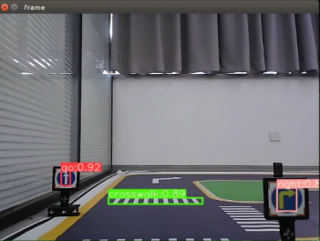
7.4.5 Autonomous Parking
This section demonstrates how to detect and recognize parking signs through command instructions.
7.4.5.1 Preparation
The traffic sign model in this section is a YOLOv8 trained model. For more details on YOLOv8, please refer to the previous sections.
When performing this feature, make sure the environment is well-lit, but avoid direct light hitting the camera to prevent misrecognition.
7.4.5.2 Project Process
First, capture the real-time video from the camera and perform image processing operations such as erosion and dilation.
Next, use YOLOv8 to run the model and compare the processed image with the target objects.
Finally, based on the comparison results, the robot recognizes the parking sign and automatically parks in the designated spot.
7.4.5.3 Operation Steps
Note
The following steps only enable turn sign detection in the camera feed and will not trigger the corresponding robot actions. To directly experience the autonomous driving feature, skip this lesson and refer to section 7.4.6 Comprehensive Application of Autonomous Driving in this document.
The input command should be case sensitive, and the keywords can be complemented by the Tab key.
Power on the robot and connect it to a remote control tool like VNC. For detailed information on connecting to a remote desktop, please refer to the section 1.7.2 AP Mode Connection Steps in the user manual.
Power on the robot and connect it to a remote control tool like VNC.
Click the terminal icon
in the system desktop to open a command-line window.Enter the following command and press Enter to stop the app auto-start service.
~/.stop_ros.sh
Enter the following command to start the feature:
ros2 launch yolov8_detect yolov8_detect_demo.launch.py
To exit the feature, press Ctrl+C in the terminal. If the program does not close successfully, try pressing Ctrl+C again.
7.4.5.4 Program Outcome
After starting the feature, place the robot on the roadway of the map. When the robot reaches the parking sign, it will follow the sign’s instructions and automatically park in the designated spot.
7.4.6 Comprehensive Application of Autonomous Driving
This section demonstrates the comprehensive autonomous driving functionality of the robot through commands. It integrates multiple features, including lane keeping, traffic sign detection, traffic light recognition, turning decision making, and autonomous parking.
7.4.6.2 Project Process
The robot is currently capable of performing the following actions:
Following the outer yellow line of the map.
Slowing down when crossing a crosswalk.
Turning when a turn sign is detected.
Parking when a stop sign is detected.
Stopping at red lights.
Slowing down when a streetlight is detected.
First, load the YOLOv8-trained model file along with the required libraries, and obtain the real-time video feed from the camera. The input image is pre-processed using erosion, dilation, and other operations.
Next, detect the target color line in the image, and extract key information such as the size and center point of the detected region. Then, apply the YOLOv8 model to compare the processed image with the target dataset.
Finally, calculate the offset of the target center point, and adjust the robot’s heading accordingly to keep it aligned in the middle of the road. During navigation, the robot also executes specific actions based on the detected traffic signs.
7.4.6.1 Preparation
Map Preparation
The map should be laid on a flat surface, ensuring it is smooth without wrinkles, and that the road is clear of any obstacles. All road signs and traffic lights must be placed at the designated positions on the map, facing clockwise along the route. The positions of the road signs and the starting point are shown in the figure below.
Color Threshold Setting
Since lighting conditions affect color recognition, it is necessary to adjust the thresholds for black, white, red, green, blue, and yellow before starting, following the instructions in 6. ROS + OpenCV Course.
If the robot encounters inaccurate recognition during its movement, the color threshold should be adjusted in areas of the map where recognition fails.
7.4.6.3 Operation Steps
Power on the robot and connect it to a remote control tool like VNC. For detailed information on connecting to a remote desktop, please refer to the section 1.7.2 AP Mode Connection Steps in the user manual.
Click the terminal icon
 in the system desktop to open a command-line window.
Enter the following command and press Enter to stop the app auto-start service.
~/.stop_ros.sh
In the terminal, enter the following command and press Enter:
ros2 launch example self_driving.launch.py
To close the program, select the corresponding terminal window and press Ctrl + C.
7.4.6.4 Program Outcome
Lane Keeping
After the program is started, the robot follows the yellow line at the edge of the road. Depending on whether the yellow line is straight or curved, it will move forward or turn accordingly to stay within the lane.
Traffic Light Recognition
When encountering a traffic light, the robot will stop if the light is red and move forward if the light is green. When crossing a crosswalk, the robot will automatically reduce its speed and proceed slowly.
Turn Signs and Parking Signs
While moving forward, if the robot detects a traffic sign, it will take the corresponding action. If a right-turn sign is detected, the robot will turn right and continue moving forward. If a parking sign is detected, the robot will perform parallel parking.
Following these rules, the robot continuously navigates around the map in a loop.
7.4.6.5 Program Analysis
The source code for the program is located at: ros2_ws/src/example/example/self_driving/self_driving.py
Functions:
def main():
    node = SelfDrivingNode('self_driving')
    executor = MultiThreadedExecutor()
    executor.add_node(node)
    executor.spin()
    node.destroy_node()
Launches the autonomous driving class.
Class:
class SelfDrivingNode(Node):
    def __init__(self, name):
        rclpy.init()
        super().__init__(name, allow_undeclared_parameters=True, automatically_declare_parameters_from_overrides=True)
        self.name = name
        self.is_running = True
        self.pid = pid.PID(0.005, 0.0, 0.0)
        self.param_init()
init
        super().__init__(name, allow_undeclared_parameters=True, automatically_declare_parameters_from_overrides=True)
        self.name = name
        self.is_running = True
        self.pid = pid.PID(0.005, 0.0, 0.0)
        self.param_init()

        self.image_queue = queue.Queue(maxsize=2)
        self.classes = ['go', 'right', 'park', 'red', 'green', 'crosswalk']
        self.display = False
        self.bridge = CvBridge()
        self.lock = threading.RLock()
        self.colors = common.Colors()
        self.machine_type = os.environ['MACHINE_TYPE']
        # signal.signal(signal.SIGINT, self.shutdown)
        self.lane_detect = lane_detect.LaneDetector("yellow")
        self.cmd_vel_topic = '/controller/cmd_vel'

        # Debug Mode
        self.debug_mode = self.get_parameter('debug_mode').value
        if self.debug_mode:
            self.cmd_vel_topic = '/controller/cmd_vel1'

        self.mecanum_pub = self.create_publisher(Twist, '%s' % self.cmd_vel_topic, 1)
        self.servo_state_pub = self.create_publisher(SetPWMServoState, 'ros_robot_controller/pwm_servo/set_state', 10)

        # self.joints_pub = self.create_publisher(ServosPosition, '/servo_controller', 1) # Servo control
        self.result_publisher = self.create_publisher(Image, '~/image_result', 1)

        self.create_service(Trigger, '~/enter', self.enter_srv_callback) # Enter the feature
        self.create_service(Trigger, '~/exit', self.exit_srv_callback) # Exit the feature
        self.create_service(SetBool, '~/set_running', self.set_running_srv_callback)
        Heart(self, self.name + '/heartbeat', 5, lambda _: self.exit_srv_callback(request=Trigger.Request(), response=Trigger.Response()))  # Heartbeat package
        timer_cb_group = ReentrantCallbackGroup()
        self.client = self.create_client(Trigger, '/controller_manager/init_finish')
        self.client.wait_for_service()
        self.client = self.create_client(Trigger, '/yolo/init_finish')
        self.client.wait_for_service()
        self.start_yolov8_client = self.create_client(Trigger, '/yolo/start', callback_group=timer_cb_group)
        self.start_yolov8_client.wait_for_service()
        self.stop_yolov8_client = self.create_client(Trigger, '/yolo/stop', callback_group=timer_cb_group)
        self.stop_yolov8_client.wait_for_service()

        self.timer = self.create_timer(0.0, self.init_process, callback_group=timer_cb_group)
Initializes required parameters, identifies the current robot type, sets the line-following color to yellow, starts chassis control, servo control, and image acquisition. Also sets up three services including enter, exit, and start, and connects to the yolov8 node.
init_process
    def init_process(self):
        self.timer.cancel()

        self.mecanum_pub.publish(Twist())
        if not self.get_parameter('only_line_follow').value:
            self.send_request(self.start_yolov8_client, Trigger.Request())
            # set_servo_position(self.joints_pub, 1, ((10, 500), (5, 500), (4, 250), (3, 0), (2, 750), (1, 500)))  # Initial position
        time.sleep(1)
        self.display = False
        if self.get_parameter('start').value:
            self.display = True
            self.enter_srv_callback(Trigger.Request(), Trigger.Response())
            request = SetBool.Request()
            request.data = True
            self.set_running_srv_callback(request, SetBool.Response())

        if 'Acker' in self.machine_type:
            servo_state = PWMServoState()
            servo_state.id = [1]
            servo_state.position = [1500]
            data = SetPWMServoState()
            data.state = [servo_state]
            data.duration = 0.02
            self.servo_state_pub.publish(data)

        #self.park_action()
        if self.debug_mode:
            threading.Thread(target=self.debug_function, daemon=True).start()
        else:
            threading.Thread(target=self.main, daemon=True).start()
        self.create_service(Trigger, '~/init_finish', self.get_node_state)
        self.get_logger().info('\033[1;32m%s\033[0m' % 'start')
Initializes the robot arm and starts the main function.
param_init
    def param_init(self):
        self.start = False
        self.enter = False

        self.have_turn_right = False
        self.detect_turn_right = False
        self.detect_far_lane = False
        self.park_x = -1  # Obtain the x-pixel coordinate of a parking sign
        self.park_y = -1  # Obtain the y-pixel coordinate of a parking sign

        self.start_turn_time_stamp = 0
        self.count_turn = 0
        self.start_turn = False  # Start to turn
Initializes parameters for position recognition and other required operations.
get_node_state
    def get_node_state(self, request, response):
        response.success = True
        return response
Retrieves the current state of the node.
send_request
    def send_request(self, client, msg):
        future = client.call_async(msg)
        while rclpy.ok():
            if future.done() and future.result():
                return future.result()
Publishes a service request.
enter_srv_callback
    def enter_srv_callback(self, request, response):
        self.get_logger().info('\033[1;32m%s\033[0m' % "self driving enter")
        with self.lock:
            self.start = False
            if self.get_parameter('use_depth_cam').value:
                self.camera = 'depth_cam'
                self.image_sub = self.create_subscription(Image, '/%s/rgb0/image_raw' % self.camera, self.image_callback, 1)  # Subscribe to the camera
            else:
                self.camera = 'usb_cam'
                self.image_sub = self.create_subscription(Image, '/%s/image_raw' % self.camera, self.image_callback, 1)  # Subscribe to the camera
            self.create_subscription(ObjectsInfo, '/yolov8/object_detect', self.get_object_callback, 1)
            self.mecanum_pub.publish(Twist())
            self.enter = True
        response.success = True
        response.message = "enter"
        return response
Service callback for entering autonomous driving mode, starts image acquisition, YOLOv8 recognition, and initializes speed.
exit_srv_callback
    def exit_srv_callback(self, request, response):
        self.get_logger().info('\033[1;32m%s\033[0m' % "self driving exit")
        with self.lock:
            try:
                if self.image_sub is not None:
                    self.image_sub.unregister()
                if self.object_sub is not None:
                    self.object_sub.unregister()
            except Exception as e:
                self.get_logger().info('\033[1;32m%s\033[0m' % str(e))
            self.mecanum_pub.publish(Twist())
        self.param_init()
        response.success = True
        response.message = "exit"
        return response
Service callback for exiting autonomous driving mode, stops image acquisition and YOLOv8 recognition, resets speed, and restores parameters.
set_running_srv_callback
    def set_running_srv_callback(self, request, response):
        self.get_logger().info('\033[1;32m%s\033[0m' % "set_running")
        with self.lock:
            self.start = request.data
            if not self.start:
                self.mecanum_pub.publish(Twist())
        response.success = True
        response.message = "set_running"
        return response
Service callback for starting autonomous driving by setting the start parameter to True.
Shutdown
    def shutdown(self, signum, frame):  # Press Ctrl+C to close the program
        self.is_running = False
Callback executed when the program is closed, used to stop any ongoing processes.
image_callback
    def image_callback(self, ros_image):  # Callback target checking
        cv_image = self.bridge.imgmsg_to_cv2(ros_image, "rgb8")
        rgb_image = np.array(cv_image, dtype=np.uint8)
        if self.image_queue.full():
            # If the queue is full, remove the oldest image
            self.image_queue.get()
        # Put the image into the queue
        self.image_queue.put(rgb_image)
Image callback function, enqueues received images while discarding outdated frames.
park_action
    def park_action(self):
        if 'Mecanum' in self.machine_type:
            twist = Twist()
            twist.linear.y = -0.2
            self.mecanum_pub.publish(twist)
            time.sleep(0.38/0.2)
            self.mecanum_pub.publish(Twist())
        elif 'Acker' in self.machine_type:
            twist = Twist()
            twist.linear.x = 0.15
            twist.angular.z = -0.55
            self.mecanum_pub.publish(twist)
            time.sleep(3)

            twist = Twist()
            twist.linear.x = 0.15
            twist.angular.z = 0.55
            self.mecanum_pub.publish(twist)
            time.sleep(2)

            twist = Twist()
            twist.linear.x = -0.15
            twist.angular.z = -0.55
            self.mecanum_pub.publish(twist)
            time.sleep(1.5)
            self.mecanum_pub.publish(Twist())
            servo_state = PWMServoState()
            servo_state.id = [1]
            servo_state.position = [1500]
            data = SetPWMServoState()
            data.state = [servo_state]
            data.duration = 0.02
            self.servo_state_pub.publish(data)
            twist = Twist()
            twist.linear.x = -0.15
            self.mecanum_pub.publish(twist)
            time.sleep(1.5)
            self.mecanum_pub.publish(Twist())
Parking logic executes different parking strategies depending on the chassis type.
get_object_callback
    def get_object_callback(self, msg):
        self.objects_info = msg.objects
        if self.objects_info == []:  # If it is not recognized, reset the variable
            self.traffic_signs_status = None
            self.crosswalk_distance = 0
            self.park_y = -1
        else:
            min_distance = 0
            for i in self.objects_info:
                class_name = i.class_name
                center = (int((i.box[0] + i.box[2])/2), int((i.box[1] + i.box[3])/2))
                if class_name == 'crosswalk':
                    if center[1] > min_distance:  # Obtain recent y-axis pixel coordinate of the crosswalk
                        min_distance = center[1]
                elif class_name == 'right':  # Obtain the right turning sign
                    area = abs(i.box[0] - i.box[2])*abs(i.box[1] - i.box[3])
                    if area > 200:
                        if not self.turn_right:
                            self.count_right += 1
                            self.count_right_miss = 0
                            if self.count_right >= 1:  # If it is detected multiple times, take the right turning sign to true
                                self.have_turn_right = True
                                self.detect_turn_right = True
                                self.count_right = 0
                    else:
                        self.get_logger().info('right tag too far')
                elif class_name == 'park':  # Obtain the center coordinate of the parking sign
                    area = abs(i.box[0] - i.box[2])*abs(i.box[1] - i.box[3])
                    if area > 150:
                        self.park_x = center[0]
                    self.park_y = center[1]
                elif class_name == 'red' or class_name == 'green':  # Obtain the status of the traffic light
                    self.traffic_signs_status = i

            self.crosswalk_distance = min_distance
Callback for YOLOv8 results, retrieves the current recognized classes.
Main
    def main(self):
        while self.is_running:
            time_start = time.time()
            try:
                image = self.image_queue.get(block=True, timeout=1)
            except queue.Empty:
                if not self.is_running:
                    break
                else:
                    continue
            result_image = image.copy()
            if self.start:
                h, w = image.shape[:2]
                # self.get_logger().info('\033[1;32m%d,%d\033[0m' %(h, w))  # Output the height and width, w
                # Obtain the binary image of the lane
                binary_image = self.lane_detect.get_binary(image)
                # cv2.imshow('binary', binary_image)
                # If detecting the zebra crossing, start to slow down
                if 300 < self.crosswalk_distance and not self.start_slow_down:  # The robot starts to slow down only when it is close enough to the zebra crossing, which is determined by judging the y-axis pixel distance of the zebra crossing
                    self.count_crosswalk += 1
                    if self.count_crosswalk == 3:  # Judge multiple times to prevent false detection
                        self.count_crosswalk = 0
                        self.start_slow_down = True  # Sign for slowing down
                        self.count_slow_down = time.time()  # Start timestamp for slowing down
                else:  # Need to detect continuously, otherwise reset
                    self.count_crosswalk = 0
Main function of the class, executes different line-following strategies based on the chassis type.