6. ROS+OpenCV Course
6.1 Color Threshold Adjustment
The color of an object can change with the light sources, which can affect the functionality involved color recognition. To tackle this issue, this lesson will introduce you how to use LAB Tool to adjust the color threshold.
6.1.1 Open/Close LAB TOOL
Note
The entered command should be case sensitive, and the “Tab” key can be used to complement key words.
Please strictly follow the operation steps; otherwise, you will fail to open LAB tool.
(1) Start the robot and connect it to Nomachine remote connection software.
(2) Click on  to start the command line terminal.
(3) Input the command and press Enter to disable app auto-start service.
sudo systemctl stop start_app_node.service
(4) Input the command and press Enter to enable the camera node.
ros2 launch peripherals depth_camera.launch.py
(5) Open a new command-line terminal and input the command to open LAB tool.
python3 /home/ubuntu/software/lab_tool/main.py
(6) Regarding the interface button instructions and usage, you can refer to the following content. If you want to close it, please click on and select “Yes” in the popup window.
(6) After closing LAB tool, press “Ctrl+C” to close the terminal, and input the command to restart app auto-start service. After the service is enable, robot arm will restore the initial po
sudo systemctl restart start_app_node.service
Note
If you do not enable app auto-start service for the robot, it will affect the corresponding app functions. Restarting robot can also automatically enable the app auto-start service.
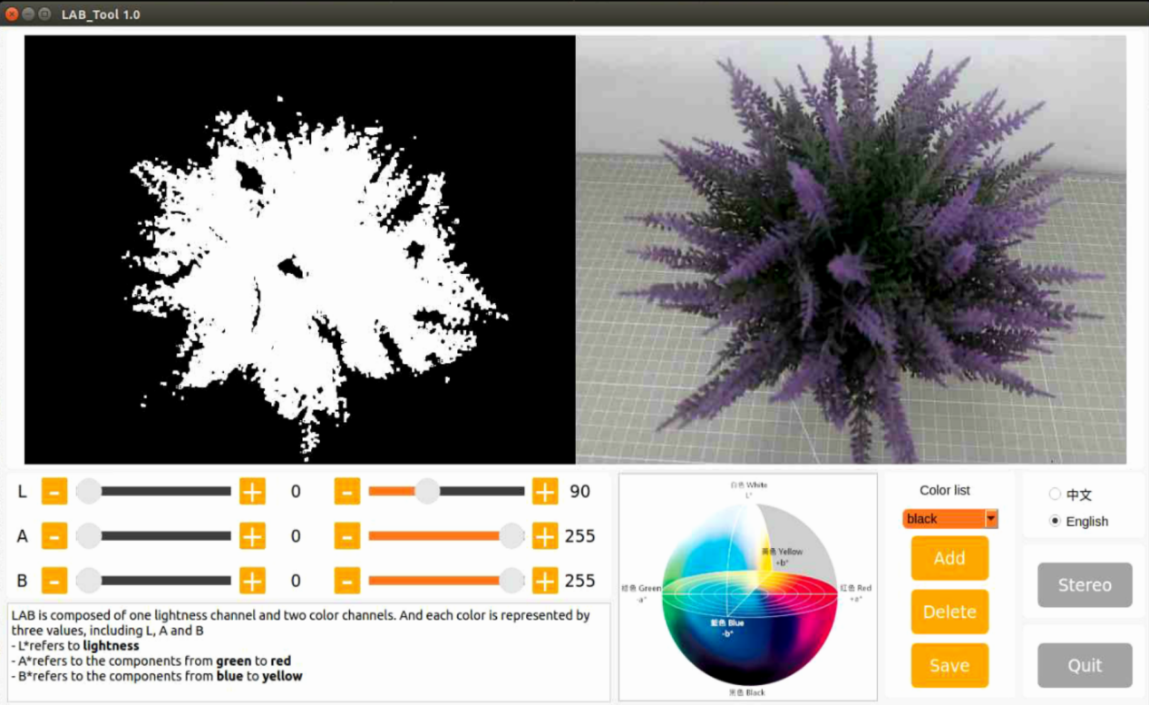
6.1.2 LAB TOOL Interface Layout Instruction
The interface of LAB tool software is divided into two parts: image display area and recognition adjustment area.
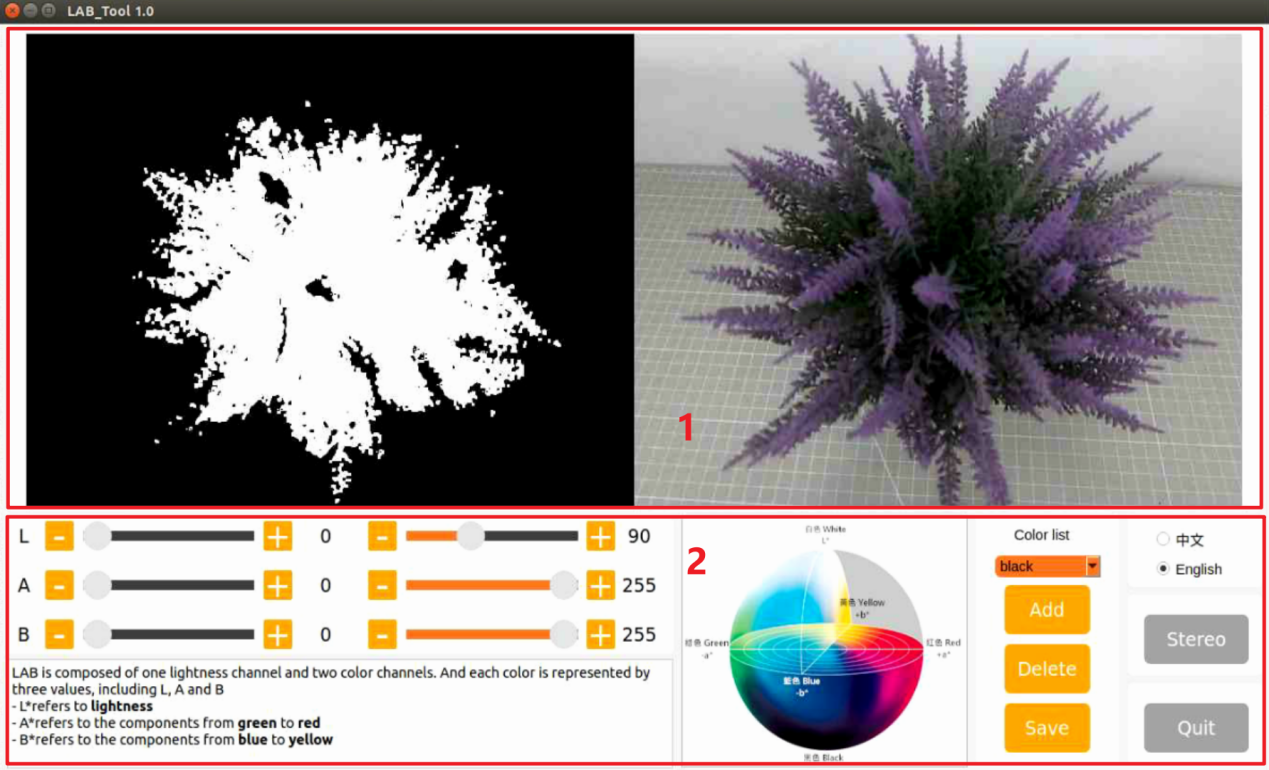
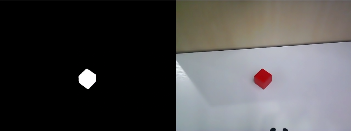
(1) Image display area: the left displays the processed image and the right is the raw image.
Note
if the transmitted image does not display normally, it’s the issue of camera connection. In this case, you need to examine if the wiring is connected properly or reconnect it.
(2) Recognition adjustment area: adjust the color threshold. The function of each button refer to the following table:
| Icon | Function instruction |
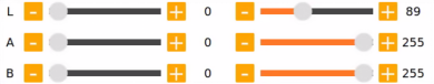 |
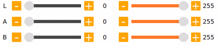
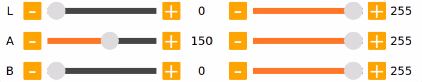
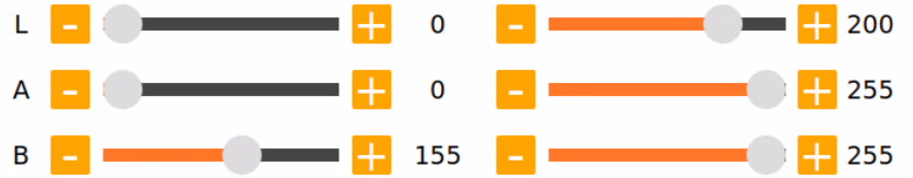
The sliders L, A and B are used respectively to adjust the values of the corresponding L, A and B components of the image. The sliders on the left are the "**min**" value for each component while the slider on the right are the "max"value for each component. |
 |
Choose color to adjust the threshold. |
 |
Delete the currently selected color. |
 |
Add recognizable color. |
 |
Save the adjustment result of the color threshold. |
 |
Click on this button to swap Depth camera/monocular camera. |
 |
Close LAB TOOL. |
6.1.3 Adjust Color Threshold
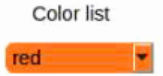
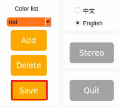
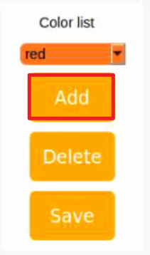
(1) Open LAB tool. Choose the color in the color drop-down list of color recognition area. Take a color “red” as example.
(2) Adjust the “min”values of L, A and B components to “0”, the “max”values to “225”.
(3) Place the target within the camera’s field of view. Adjust the values of L, A and B component towards the interval representing the target recognition color according to the LAB color space distribution chart.
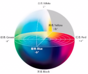
Red color is close to “+a”, which indicates that A component needs to be increased. Therefore, keep the “max”value of the A component unchanged and increase its “min”value until the object on the left turns white while other areas turn black.
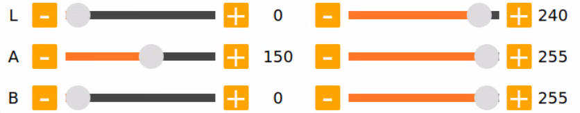
(4) Adjust the L and B components according to your surroundings. If the red color is light, increase the “min”value of the L component; if it is dark, decrease the “max”value of the component. If the red color tends to be warm, increase the “min” value of the B component; if it tends to be cool, decrease the “max” value of the B component.
The following table shows the parameter information of LAB threshold adjustment:
| Color component | Value Range | **Corresponding Color Intervals ** |
|---|---|---|
| L | 0~255 | Black-white (-L~+L) |
| A | 0~255 | green-red(-a ~ +a) |
| B | 0~255 | Blue-yellow(-b ~ +b) |
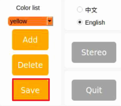
(5) Click “Save”button in adjustment area to save the adjustment parameters.
6.1.4 Add New Color
In addition to the built-in colors, users can add other recognition colors. Take an example of adding “yellow”.
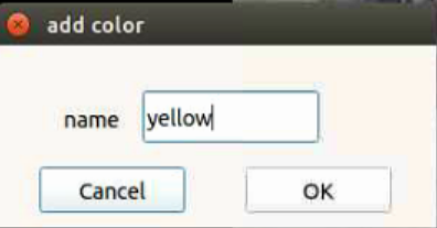
(1) Open LAB tool and click on “Add”button.
(2) Fill in the “name” column with the color name, and click the “OK” button.
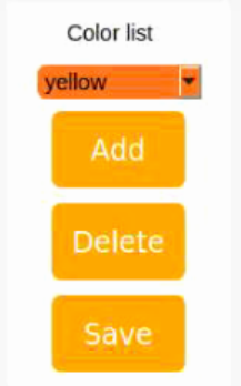
(3) Choose the added color in the color drop-down menu.
(4) Place the target within the camera’s field of view, and adjust the threshold by dragging the L, A, and B component sliders until the area of the colored object within the left screen turns white, while the other areas turn black.
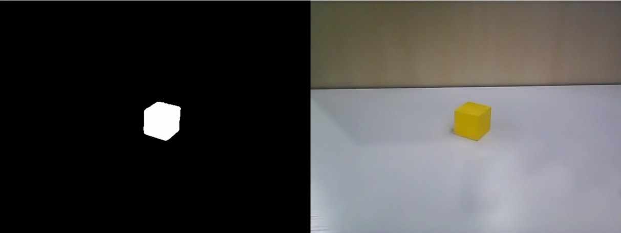
Note
the adjustment method of color threshold refers to 6.1.3 Adjust Color Adjustment.
(5) Click “Save”button in recognition adjustment area to save the adjustment parameters of color threshold.
After adjusting the color thresholds, press ‘Ctrl+C’ to stop the camera service, then click ‘Close Software’ to close the interface.
6.2 Color Recognition
This session will use OpenCV to perform red, green, blue recognition and display the recognition result through transmitted image. Before operations, please prepare one object of red, green and blue.
6.2.1 Recognition Process
Firstly, obtain the RGB image from the camera. Scale and apply Gaussian blur to the image. Convert the image from RGB to Lab. (For detailed explanations regarding the Lab color space.
Next, identify the object color in the circle by using color thresholds, followed by masking of the image portion. (masking is used to hide certain part of the processed image).
After performing opening and closing operations on the object image, the object with the largest contour is circled.
Open operations: erosion followed by dilation. Remove small objects, smooth the contours of object and keep its area unchanged. It can eliminate small noise and break thin connection between objects.
Erosion: it can be used to remove small objects or features from an image, break thin connections between objects, and generally reduce the size of objects.
Dilation: it is useful for filling in gaps between objects, joining nearby objects, and generally increasing the size of objects.
Finally, the recognition results are displayed on the screen.
6.2.2 Operation Steps
Note
the entered command should be case sensitive and “Tab” key can be used to complement the key words.
(1) Start JetAuto and connect it to Nomachine.
(2) Click on to start the command line terminal.
(3) Input the command and press Enter to disable the app auto-start service.
sudo systemctl stop start_app_node.service
(4) Run the following command to enable the camera node:
ros2 launch peripherals depth_camera.launch.py
(5) Open a new command line terminal, enter the following command to navigate to the program directory and start the color recognition game:
cd ~/ros2_ws/src/example/example/color_detect && python3 color_detect_demo.py
(6) Next, press “Ctrl+C” in the command line terminal interface. If closing fails, please try again repeatedly.
6.2.3 Program Outcome
Note
After the game starts, please ensure that there are no other objects containing recognized colors within the field of view of the camera to avoid affecting the implementation effect.
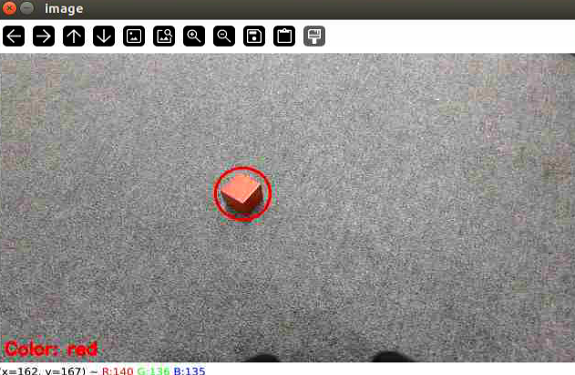
After the game starts, place the target object within the field of view of the camera. When recognizing the target object, it will be circled up in the same color and the color name will be printed in the lower-left corner of the screen. The program supports red, blue and green object recognition.
6.2.4 Program Analysis
The source code of the program is located in
/home/ubuntu/ros2/_ws/src/example/example/color_detect/color_detect_demo.py
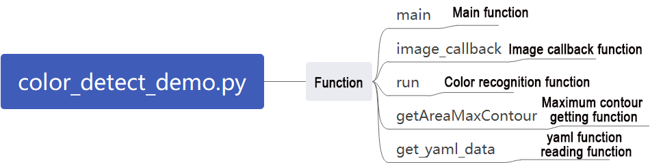
Main Function
(1) Main Function
Initialize the ROS node, create a color recognition node named color_detect_node, subscribe to the image topic /depth_cam/rgb/image_raw, and set its callback function to image_callback. Start the main function for color recognition using multiple threads. Wait for the node to shut down.
157 158 159 160 161 162 | if __name__ == '__main__': rclpy.init() node = rclpy.create_node('color_detect_node') node.create_subscription(Image, '/depth_cam/rgb/image_raw', image_callback, 1) threading.Thread(target=main, daemon=True).start() rclpy.spin(node) |
Image Processing
(1) Camera Callback Function
Primarily used to read the video stream from the topic and enqueue it to ensure real-time display.
129 130 131 132 133 134 135 136 | def image_callback(ros_image): cv_image = bridge.imgmsg_to_cv2(ros_image, "bgr8") bgr_image = np.array(cv_image, dtype=np.uint8) if image_queue.full(): # If the queue is full, remove the oldest image(如果队列已满,丢弃最旧的图像) image_queue.get() # Put the image into the queue(将图像放入队列) image_queue.put(bgr_image) |
(2) Color Recognition Main Function
This function reads image data from the queue, processes it using the run function for color recognition, and then displays the recognized image using cv2.
138 139 140 141 142 143 144 145 146 147 148 149 150 151 152 153 154 155 | def main(): running = True while running: try: image = image_queue.get(block=True, timeout=1) except queue.Empty: if not running: break else: continue image = run(image) cv2.imshow('image', image) key = cv2.waitKey(1) if key == ord('q') or key == 27: # Press Q or Esc to quit(按q或者esc退出) break cv2.destroyAllWindows() rclpy.shutdown() |
(3) YAML File Reading Function
28 29 30 31 32 33 34 35 36 37 | def get_yaml_data(yaml_file): yaml_file = open(yaml_file, 'r', encoding='utf-8') file_data = yaml_file.read() yaml_file.close() data = yaml.load(file_data, Loader=yaml.FullLoader) return data lab_data = get_yaml_data("/home/ubuntu/software/lab_tool/lab_config.yaml") |
(4) Maximum Contour Function
This function takes contours detected by OpenCV as input, identifies the largest contour based on size, and returns the contour along with its area.
39 40 41 42 43 44 45 46 47 48 49 50 51 52 53 | # Find out the contour with the maximal area(找出面积最大的轮廓) # The parameter is the list of contour to be compared(参数为要比较的轮廓的列表) def getAreaMaxContour(contours): contour_area_temp = 0 contour_area_max = 0 area_max_contour = None for c in contours: # Iterate through all contours(历遍所有轮廓) contour_area_temp = math.fabs(cv2.contourArea(c)) # Calculate contour area(计算轮廓面积) if contour_area_temp > contour_area_max: contour_area_max = contour_area_temp if contour_area_temp > 50: # Only contours with an area greater than 50 are considered valid, and among them, the contour with the largest area is selected to filter out interference(只有在面积大于50时,最大面积的轮廓才是有效的,以过滤干扰) area_max_contour = c return area_max_contour, contour_area_max # Return the maximal contour(返回最大的轮廓) |
(5) Color Recognition Function
This function compresses the input image to a size of (320, 240) for easier detection, applies Gaussian filtering, and then converts the image to the LAB color space.
60 61 62 63 64 65 66 67 68 69 70 71 72 73 74 | def run(img): global draw_color global color_list global detect_color img_copy = img.copy() img_h, img_w = img.shape[:2] frame_resize = cv2.resize(img_copy, size, interpolation=cv2.INTER_NEAREST) frame_gb = cv2.GaussianBlur(frame_resize, (3, 3), 3) frame_lab = cv2.cvtColor(frame_gb, cv2.COLOR_BGR2LAB) # Convert the image to LAB space(将图像转换到LAB空间) max_area = 0 color_area_max = None areaMaxContour_max = 0 |
The function iterates through a list of colors to identify the color of the largest detected contour.
76 77 78 79 80 81 82 83 84 85 86 | for i in ['red', 'green', 'blue']: frame_mask = cv2.inRange(frame_lab, tuple(lab_data['lab']['Stereo'][i]['min']), tuple(lab_data['lab']['Stereo'][i]['max'])) #Perform bitwise operations on the original image and mask(对原图像和掩模进行位运算) eroded = cv2.erode(frame_mask, cv2.getStructuringElement(cv2.MORPH_RECT, (3, 3))) #Corrosion(腐蚀) dilated = cv2.dilate(eroded, cv2.getStructuringElement(cv2.MORPH_RECT, (3, 3))) #Dilation(膨胀) contours = cv2.findContours(dilated, cv2.RETR_EXTERNAL, cv2.CHAIN_APPROX_NONE)[-2] #Find out contours(找出轮廓) areaMaxContour, area_max = getAreaMaxContour(contours) #Find out the contour with the maximum area(找出最大轮廓) if areaMaxContour is not None: if area_max > max_area:#Find the maximal area(找最大面积) max_area = area_max color_area_max = i areaMaxContour_max = areaMaxContour |
Contours with an area smaller than 200 are filtered out. If the area is larger than 200, the function calculates the contour coordinates and draws the detected color’s position on the screen.
87 88 89 90 91 92 93 94 95 96 97 98 99 100 101 102 103 104 105 106 107 108 109 110 111 112 113 114 115 116 117 118 119 120 121 122 123 124 125 126 127 128 | if max_area > 200: # The maximum area is found(有找到最大面积) ((centerX, centerY), radius) = cv2.minEnclosingCircle(areaMaxContour_max) # Get the minimum circumcircle(获取最小外接圆) centerX = int(common.val_map(centerX, 0, size[0], 0, img_w)) centerY = int(common.val_map(centerY, 0, size[1], 0, img_h)) radius = int(common.val_map(radius, 0, size[0], 0, img_w)) cv2.circle(img, (centerX, centerY), radius, range_rgb[color_area_max], 2)#Draw circle(画圆) if color_area_max == 'red': #Red is the maximal area(红色最大) color = 1 elif color_area_max == 'green': #Green is the maximal area(绿色最大) color = 2 elif color_area_max == 'blue': #Blue is the maximal area(蓝色最大) color = 3 else: color = 0 color_list.append(color) if len(color_list) == 3: #Multiple judgement(多次判断) # Take average value(取平均值) color = int(round(np.mean(np.array(color_list)))) color_list = [] if color == 1: detect_color = 'red' draw_color = range_rgb["red"] elif color == 2: detect_color = 'green' draw_color = range_rgb["green"] elif color == 3: detect_color = 'blue' draw_color = range_rgb["blue"] else: detect_color = 'None' draw_color = range_rgb["black"] else: detect_color = 'None' draw_color = range_rgb["black"] cv2.putText(img, "Color: " + detect_color, (10, img.shape[0] - 10), cv2.FONT_HERSHEY_SIMPLEX, 0.65, draw_color, 2) return img image_queue = queue.Queue(2) |
6.3 Generate & Recognize QR Code
This lesson is divided into two parts. The first part will introduce you how to learn to create a QR code, while the second part focuses on recognizing the created QR code and then decoding the QR code information through the terminal.
6.3.1 Generate QR Code
Process
First, create an instance object of the QR code tool and set its detailed parameters.
Next, obtain the user’s data and fill it into the QR code.
Finally, generate a QR CODE image based on the data and display it in a window, and save it in the corresponding path.
Operation Steps
Note
the entered command should be case sensitive and the “Tab” key can be used to fill in key words.
(1) Start the robot and connect it to Nomachine.
(2) Click on to start the command line terminal.
(3) Input the command and press Enter to disable the app auto-start service.
sudo systemctl stop start_app_node.service
(4) Input the command to access the program directory and start the QR code creation program. After start the program, it’s necessary to enter characters in the terminal to generate the QR code. Take the input of “ubuntu” as example.
cd ~/ros2_ws/src/example/example/qrcode && python3 qrcode_creater.py
Press “Enter”to display a QR code image containing the input data.

(5) If need to close the program, press “Esc” or “q” on the qr code window.
(6) Back to the command line terminal. If the following content prompts, indicating the qr card is successfully generated than saved.

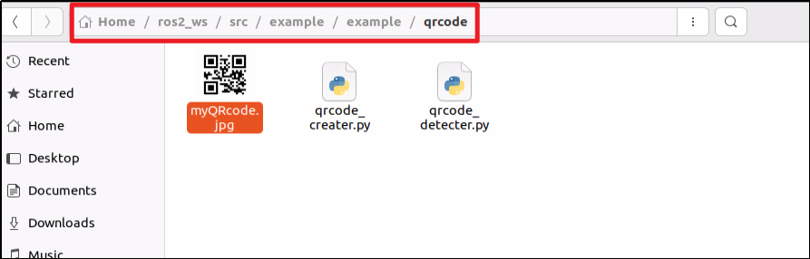
(7) Next, we click on  on the left side of the system interface, then click to open the file manager, and navigate to the directory highlighted in the red box in the screenshot below. Here, you can see that the generated QR code has been exported to the host system.
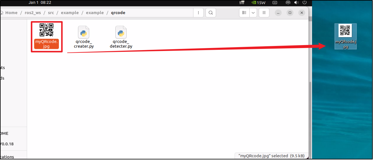
(8) Drag the image to your PC desktop using the NoMachine tool’s drag-and-drop feature. Then, you can print it out or transfer it to your mobile phone’s photo album.
Program Analysis
The source code of this program is located at:
/home/ubuntu/ros2_ws/src/example/example/qrcode/qrcode_creater.py
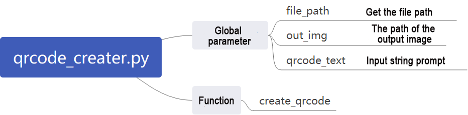
(1) Creating QR Code Utility Object
Using the qrcode module to create the necessary object and setting various parameters for the QR code.
19 20 21 22 23 | qr = qrcode.QRCode( version=1, error_correction=qrcode.constants.ERROR_CORRECT_H, box_size=5, border=4) |
The parameters of the above function are as follows:
The first parameter “version” is an integer ranging from 1 to 40, used to control the size of the QR code. If you want the program to automatically determine the size, set this value to None and use the “fit” parameter.
The second parameter “error_correction” controls the error correction capability of the QR code, with the following options:
① ERROR_CORRECT_L: can correct approximately 7% or fewer errors.
② ERROR_CORRECT_M: default value, can correct approximately 15% or fewer errors.
③ ERROR_CORRECT_H: can correct approximately 30% or fewer errors.
The third parameter “box_size” controls the number of pixels contained in each small box of the QR code.
The fourth parameter “border” controls the number of boxes included in the border (distance between the QR code and the image boundary), with a default value of 4, which is the minimum value specified by relevant standards.
(2) Generating QR Code
Using the “add_data” and “make” functions to retrieve and fill data, and then using the “make_image” function to generate the image.
24 25 26 27 28 29 30 | # Add data(添加数据) qr.add_data(data) # Fill data(填充数据) qr.make(fit=True) # Generate image(生成图片) img = qr.make_image(fill_color=(0, 0, 0), back_color=(255, 255, 255)) opencv_img = cv2.cvtColor(np.asarray(img), cv2.COLOR_RGB2BGR) |
The parameters of the “make_image” function are as follows:
The first parameter “fill_color=(0, 0, 0)” is the fill color of the image, which is black in this case.
The second parameter “back_color=(255, 255, 255)” is the background color of the image, which is white in this case.
(3) Displaying Image
Converting the color space of the image using the “cvtColor” function, and then displaying it on the window using the “imshow” function.
31 32 33 34 35 | while True: cv2.imshow('img', opencv_img) k = cv2.waitKey(1) if k != -1: break |
(4) Saving Image
Using the “imwrite” function to store the generated QR code image and printing relevant information.
36 37 | cv2.imwrite(file_name, opencv_img) print('save', data, file_name) |
The parameters of the “imwrite” function are as follows:
The first parameter “file_name” is the storage path of the image.
The second parameter “opencv_img” is the image to be stored.
6.3.2 QR Code Recognition
In the previous section, we created a QR code. In this section, we’ll perform content recognition on the QR code.
Recognition Process
Firstly, create an instance object for QR code detection, and pass in the required network structure and model weight files for detection.
Then, obtain the camera’s feedback image and perform detection.
Finally, once the QR code is recognized, it will be framed, and the content of the QR code will be printed.
The source code for this program is located at: /home/ubuntu/ros2_ws/src/example/example/qrcode/qrcode_detecter.py
QR Code Recognition Steps
Note
When entering commands, it is necessary to strictly distinguish between uppercase and lowercase letters, and you can use the “Tab” key to complete keywords.
(1) Start the robot and connect it to the remote control software Nomachine.
(2) Click on  on the system desktop to start the command line terminal.
(3) Enter the command to disable the automatic startup service of the app:
sudo systemctl stop start_app_node.service
(4) Enter the command to start the camera node:
ros2 launch peripherals depth_camera.launch.py
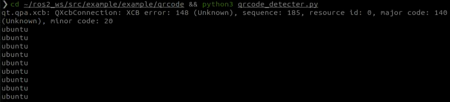
(5) Open a new ROS2 command line terminal, enter the command to switch to the program directory, and start the QR code recognition program:
cd ~/ros2_ws/src/example/example/qrcode && python3 qrcode_detecter.py
To close this game, press “Ctrl+C” in the terminal interface. If closing fails, please try again repeatedly.
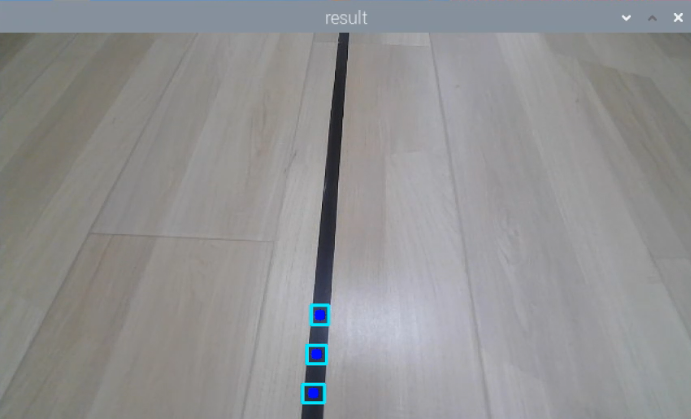
Program Outcome
After starting the game, it will recognize the QR code images appearing in the feedback screen, mark them with a red box, and print out the content of the QR code.
Program Analysis
The source code of this program is saved in /home/ubuntu/ros2_ws/src/example/example/qrcode/qrcode_detecter.py
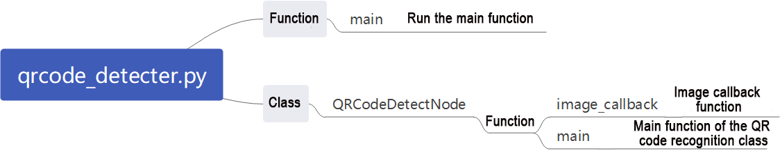
(1) Main Function
Initialize the QRCodeDetectNode and set the node name as “qrcode_detect”. Wait for the ROS node to close, and if it closes, unregister the current node.
60 61 62 63 64 65 66 67 68 69 70 71 72 | def main(): node = QRCodeDetectNode('qrcode_detect') try: rclpy.spin(node) except KeyboardInterrupt: node.destroy_node() rclpy.shutdown() print('shutdown') finally: print('shutdown finish') if __name__ == "__main__": main() |
(2) QRCodeDetectNode Class
Initialize the node and define parameters, then start the self.main function.
① Parameters:
self.running: Whether the detection is enabled
self.model_path: Model path
self.image_queue: Image queue
self.image_sub: Subscription to read camera feedback images
self.qcd: Initialization of the QR code detection
13 14 15 16 17 18 19 20 21 22 23 | class QRCodeDetectNode(Node): def __init__(self, name): rclpy.init() super().__init__(name) self.running = True self.bridge = CvBridge() self.model_path = os.path.join(os.path.abspath(os.path.split(os.path.realpath(__file__))[0]), 'model/detector.tflite') self.image_queue = queue.Queue(maxsize=2) self.image_sub = self.create_subscription(Image, '/depth_cam/rgb/image_raw', self.image_callback, 1) self.qcd = cv2.QRCodeDetector() threading.Thread(target=self.main, daemon=True).start() |
② Functions:
The camera callback function reads the camera feedback image and places it in the queue self.image_queue for automatic update and discarding of expired images.
25 26 27 28 29 30 31 32 | def image_callback(self, ros_image): cv_image = self.bridge.imgmsg_to_cv2(ros_image, "bgr8") bgr_image = np.array(cv_image, dtype=np.uint8) if self.image_queue.full(): # If the queue is full, remove the oldest image(如果队列已满,丢弃最旧的图像) self.image_queue.get() # Put the image into the queue(将图像放入队列) self.image_queue.put(bgr_image) |
The main function begins by performing QR code detection. It checks the self.running parameter to determine whether to start detection. If True, it reads image data from the self.image_queue queue, inputs it into the initialized recognition model self.qcd, and finally prints the recognition results and draws recognition boxes based on the output data.
34 35 36 37 38 39 40 41 42 43 44 45 46 47 48 49 50 51 52 53 54 55 56 57 58 | def main(self): while self.running: try: image = self.image_queue.get(block=True, timeout=1) except queue.Empty: if not self.running: break else: continue ret_qr, decoded_info, points, _ = self.qcd.detectAndDecodeMulti(image) if ret_qr: for s, p in zip(decoded_info, points): if s: print(s) color = (0, 255, 0) else: color = (0, 0, 255) image = cv2.polylines(image, [p.astype(int)], True, color, 8) cv2.imshow('image', image) key = cv2.waitKey(1) if key == ord('q') or key == 27: # Put the image into the queue(将图像放入队列) break cv2.destroyAllWindows() rclpy.shutdown() |
6.4 Autonomous Line Following
6.4.1 Recognition Procedure
First, obtain the RGB image from the camera and resize it. Apply Gaussian blur to the image and convert the color space from RGB to Lab.
Then, perform color recognition on the objects in the circle using color thresholding. Apply masking to parts of the image. (Masking is used to globally or locally mask the processed image using selected images, graphics, or objects).
Afterward, perform opening and closing operations on the object images. Finally, outline the largest object with a circle.
Opening operation: First, erode the image and then dilate it. Purpose: Used to eliminate small objects, smooth the shape boundary, and not change its area. It can remove small grain noise and break the adhesion between objects.
Erosion: Eliminate the boundary points of the object, causing the boundary to shrink inward, and can remove objects smaller than the structural element.
Dilation: Expand the boundary points of the object, merge all background points in contact with the object into the object, and expand the boundary outward.
Finally, feedback the recognition results on the feedback screen.
6.4.2 Autonomous Line Following Operation
Note
The input command should be case sensitive, and keywords can be complemented using “Tab” key.
(1) Start the robot and connect it to the remote control software Nomachine.
(2) Click on on the system desktop to start the command line terminal.
(3) Enter the command to disable the automatic startup service of the app:
sudo systemctl stop start_app_node.service
(4) Run the command to enable the camera node
ros2 launch app line_following_node.launch.py debug:=true
(5) Open a command line terminal, enter the command to navigate to the program directory, and start the line-following game:
ros2 service call /line_following/enter std_srvs/srv/Trigger {}
(6) Then, in the current command line terminal, enter the command to navigate to the program directory and start the line-following game:
ros2 service call /line_following/set_running std_srvs/srv/SetBool "{data: True}"
(7) Click on the position of the line in the image to select the corresponding color of the track line, and you can start line following by color picking.
(8) If you need to close this function, you need to return to the command line terminal and enter the command to stop it.
ros2 service call /line_following/enter std_srvs/srv/Trigger {}
If you need to close this game, press “Ctrl+C” in the terminal. If fail to close, please try multiple times.
6.4.3 Program Analysis
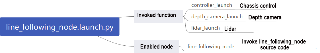
Launch Analysis:
The program file corresponding to this section of the course document is located at: /home/ubuntu/ros2_ws/src/app/launch/scripts/line_following_node.launch.py
(1) Read the Storage Path
14 15 16 17 18 19 | if compiled == 'True': controller_package_path = get_package_share_directory('controller') peripherals_package_path = get_package_share_directory('peripherals') else: controller_package_path = '/home/ubuntu/ros2_ws/src/driver/controller' peripherals_package_path = '/home/ubuntu/ros2_ws/src/peripherals' |
Use get_package_share_directory to obtain the package path.
(2) Launch
20 21 22 23 24 25 26 27 28 29 30 31 32 33 34 35 36 37 38 39 40 41 42 43 44 45 46 | line_following_node = GroupAction([ IncludeLaunchDescription( PythonLaunchDescriptionSource( os.path.join(peripherals_package_path, 'launch/lidar.launch.py')), condition=IfCondition(debug), ), IncludeLaunchDescription( PythonLaunchDescriptionSource( os.path.join(peripherals_package_path, 'launch/depth_camera.launch.py')), condition=IfCondition(debug), ), IncludeLaunchDescription( PythonLaunchDescriptionSource( os.path.join(controller_package_path, 'launch/controller.launch.py')), condition=IfCondition(debug), ), Node( package='app', executable='line_following', output='screen', parameters=[{'debug': debug}], ), ]) |
controller_launch: Start motion control launch.
depth_camera_launch: Start depth camera launch.
lidar_launch: Start lidar launch.
(3) Node
line_following_node: Start line following node.
39 40 41 42 43 44 45 | Node( package='app', executable='line_following', output='screen', parameters=[{'debug': debug}], ), ]) |
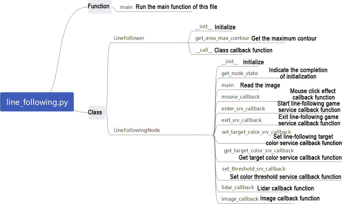
Source Code Analysis:
The program file corresponding to this section of the course document is located at:
/home/ubuntu/ros2_ws/src/app/app/line_following.py
Note
It’s necessary to back up the original program file before making any modification to the program. You’re forbidden to modify the original source code file to avoid causing robot malfunctions that may be irreparable due to incorrect parameter modifications!
According to the game’s effect, the process logic of this game is summarized as shown in the following diagram:
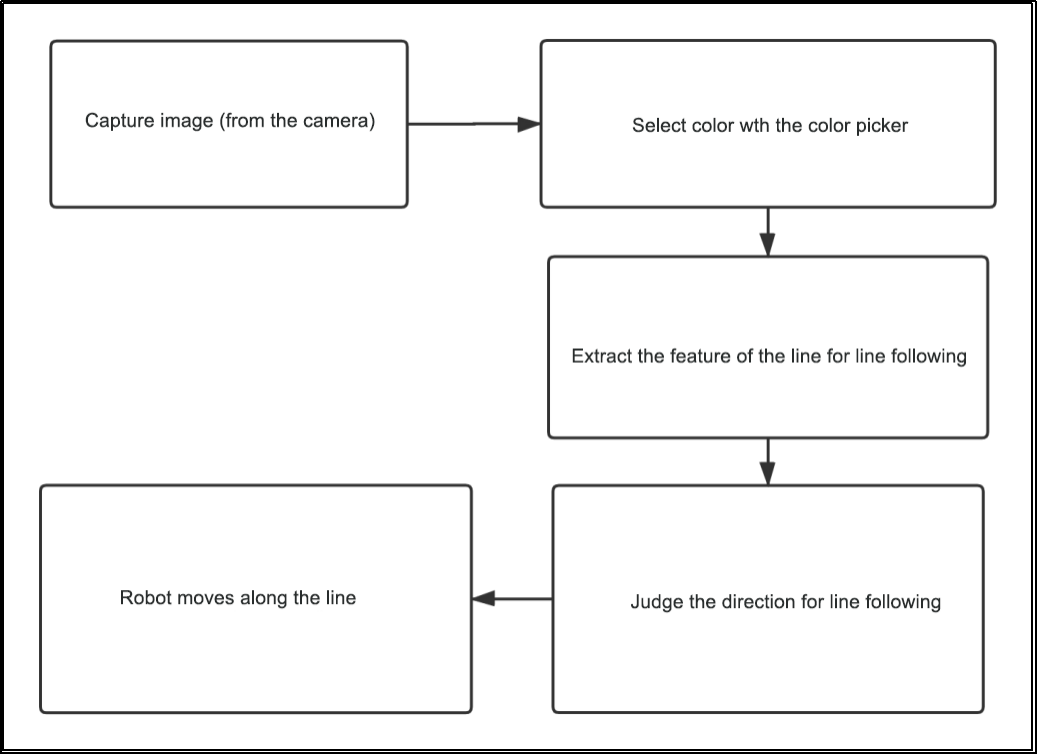
Subscribe to the topic messages published by the camera node to obtain RGB images. From the image, identify and select the target line. Determine the color threshold by picking the color of the line. Based on the line’s color information, extract the features of the line for line following. Calculate the robot’s offset relative to the line’s position in the field of view. Control the robot to move along the line segment, continuously correcting its position to keep the line at the center of the field of view and use lidar to detect obstacles and avoid them.
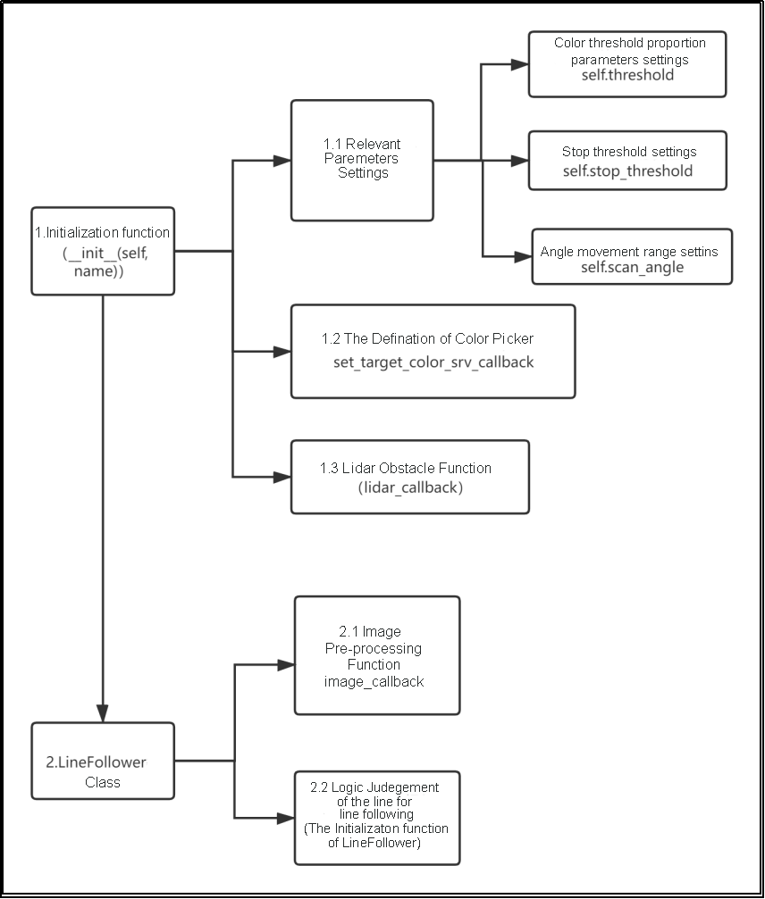
Then, the color picker object is defined (used in the game to pick colors), along with the setting of additional Lidar obstacle avoidance functionality. Next is the implementation of the LineFollower class, which mainly includes functions for image preprocessing and logic for line following.
Function:
(1) Main: Initiate line following node.
378 379 380 381 382 | def main(): node = LineFollowingNode('line_following') rclpy.spin(node) node.destroy_node() rclpy.shutdown() |
(2) Class:LineFollower.
27 | class LineFollower: |
(3)Init: Set the line-following color and ROI list.
28 29 30 31 32 | def __init__(self, color, node): self.node = node self.target_lab, self.target_rgb = color self.rois = ((0.90, 0.92, 0, 1, 0.7), (0.78, 0.80, 0, 1, 0.2), (0.66, 0.68, 0, 1, 0.1)) self.weight_sum = 1.0 |
(4) get_area_max_contour:Get the contour with the maximum area.
35 36 37 38 39 40 41 42 43 44 45 46 47 | def get_area_max_contour(contours, threshold=100): ''' Get the contour of the largest area(获取最大面积对应的轮廓) :param contours: :param threshold: :return: ''' contour_area = zip(contours, tuple(map(lambda c: math.fabs(cv2.contourArea(c)), contours))) contour_area = tuple(filter(lambda c_a: c_a[1] > threshold, contour_area)) if len(contour_area) > 0: max_c_a = max(contour_area, key=lambda c_a: c_a[1]) return max_c_a return None |
(5) Call:Perform color recognition, identify based on the set color, and provide feedback on the recognized image and angle.
46 47 48 49 50 51 52 53 54 55 56 57 58 59 60 61 62 63 64 65 66 67 68 69 70 71 72 73 74 75 76 77 | def __call__(self, image, result_image, threshold, color=None, use_color_picker=True): centroid_sum = 0 h, w = image.shape[:2] if use_color_picker: min_color = [int(self.target_lab[0] - 50 * threshold * 2), int(self.target_lab[1] - 50 * threshold), int(self.target_lab[2] - 50 * threshold)] max_color = [int(self.target_lab[0] + 50 * threshold * 2), int(self.target_lab[1] + 50 * threshold), int(self.target_lab[2] + 50 * threshold)] target_color = self.target_lab, min_color, max_color lowerb = tuple(target_color[1]) upperb = tuple(target_color[2]) else: lowerb = tuple(color['min']) upperb = tuple(color['max']) for roi in self.rois: blob = image[int(roi[0]*h):int(roi[1]*h), int(roi[2]*w):int(roi[3]*w)] # Intercept roi(截取roi) img_lab = cv2.cvtColor(blob, cv2.COLOR_RGB2LAB) # Convert rgb into lab(rgb转lab) img_blur = cv2.GaussianBlur(img_lab, (3, 3), 3) # Perform Gaussian filtering to reduce noise(高斯模糊去噪) mask = cv2.inRange(img_blur, lowerb, upperb) # Image binarization(二值化) eroded = cv2.erode(mask, cv2.getStructuringElement(cv2.MORPH_RECT, (3, 3))) # Corrode(腐蚀) dilated = cv2.dilate(eroded, cv2.getStructuringElement(cv2.MORPH_RECT, (3, 3))) # Dilate(膨胀) # cv2.imshow('section:{}:{}'.format(roi[0], roi[1]), cv2.cvtColor(dilated, cv2.COLOR_GRAY2BGR)) contours = cv2.findContours(dilated, cv2.RETR_EXTERNAL, cv2.CHAIN_APPROX_TC89_L1)[-2] # Find the contour(找轮廓) max_contour_area = self.get_area_max_contour(contours, 30) # Get the contour corresponding to the largest contour(获取最大面积对应轮廓) if max_contour_area is not None: rect = cv2.minAreaRect(max_contour_area[0]) # Minimum circumscribed rectangle(最小外接矩形) box = np.intp(cv2.boxPoints(rect)) # Four corners(四个角) for j in range(4): box[j, 1] = box[j, 1] + int(roi[0]*h) cv2.drawContours(result_image, [box], -1, (0, 255, 255), 2) # Draw the rectangle composed of four points(画出四个点组成的矩形) |
(6) LineFollowingNode:
96 | class LineFollowingNode(Node): |
(7) Init:Initialize the required parameters for the program, call the base node, camera node, and start services such as enter, exit, start, set color, get color, set threshold, etc.
97 98 99 100 101 102 103 104 105 106 107 108 109 110 111 112 113 114 115 116 117 118 119 120 121 | def __init__(self, name): rclpy.init() super().__init__(name, allow_undeclared_parameters=True, automatically_declare_parameters_from_overrides=True) self.name = name self.color = '' self.set_above = False self.set_callback = False self.is_running = False self.color_picker = None self.follower = None self.scan_angle = math.radians(45) self.pid = pid.PID(0.01, 0.0, 0.0) self.empty = 0 self.count = 0 self.stop = False self.threshold = 0.5 self.stop_threshold = 0.4 self.lock = threading.RLock() self.image_sub = None self.lidar_sub = None self.image_height = None self.image_width = None self.bridge = CvBridge() self.use_color_picker = True |
(8) get_node_state:Set the status of the current node.
144 145 146 | def get_node_state(self, request, response): response.success = True return response |
(9) Main:Read the image and use the mouse to pick colors.
148 149 150 151 152 153 154 155 156 157 158 159 160 161 162 163 164 165 166 167 168 169 | def main(self): while True: try: image = self.image_queue.get(block=True, timeout=1) except queue.Empty: continue result = cv2.cvtColor(image, cv2.COLOR_RGB2BGR) cv2.imshow("image", cv2.resize(result, (display_size[0], display_size[1]))) if self.debug and not self.set_callback: self.set_callback = True # Set callback function for mouse clicking event(设置鼠标点击事件的回调函数) cv2.setMouseCallback("image", self.mouse_callback) k = cv2.waitKey(1) if k != -1: break if self.debug and not self.set_above: cv2.moveWindow('image', 1920 - display_size[0], 0) os.system("wmctrl -r image -b add,above") self.set_above = True self.mecanum_pub.publish(Twist()) rclpy.shutdown() |
(10) mouse_callback:Mouse color picking callback function, obtains the pixel coordinates of the current mouse position.
171 172 173 174 175 176 177 178 | def mouse_callback(self, event, x, y, flags, param): if event == cv2.EVENT_LBUTTONDOWN: self.get_logger().info("x:{} y{}".format(x, y)) msg = SetPoint.Request() if self.image_height is not None and self.image_width is not None: msg.data.x = x / self.image_width msg.data.y = y / self.image_height self.set_target_color_srv_callback(msg, SetPoint.Response()) |
(11) enter_srv_callback:Enter autonomous line-following service, read data from the camera and lidar, and initialize actions.
180 181 182 183 184 185 186 187 188 189 190 191 192 193 194 195 196 197 198 199 200 | def enter_srv_callback(self, request, response): self.get_logger().info('\033[1;32m%s\033[0m' % "line following enter") with self.lock: self.color = '' self.stop = False self.is_running = False self.color_picker = None self.pid = pid.PID(1.1, 0.0, 0.0) self.follower = None self.threshold = 0.5 self.empty = 0 if self.image_sub is None: self.image_sub = self.create_subscription(Image, '/depth_cam/rgb/image_raw', self.image_callback, 1) # Subscribe to the camera(摄像头订阅) if self.lidar_sub is None: qos = QoSProfile(depth=1, reliability=QoSReliabilityPolicy.BEST_EFFORT) self.lidar_sub = self.create_subscription(LaserScan, '/scan_raw', self.lidar_callback, qos) # Subscribe to Lidar data(订阅雷达数据) set_servo_position(self.joints_pub, 1, ((1, 500), (9, 500))) self.mecanum_pub.publish(Twist()) response.success = True response.message = "enter" return response |
(12) exit_srv_callback:Exit autonomous line-following service, close various reading nodes, reset PID, and stop line following.
202 203 204 205 206 207 208 209 210 211 212 213 214 215 216 217 218 219 220 221 222 | def exit_srv_callback(self, request, response): self.get_logger().info('\033[1;32m%s\033[0m' % "line following exit") try: if self.image_sub is not None: self.destroy_subscription(self.image_sub) self.image_sub = None if self.lidar_sub is not None: self.destroy_subscription(self.lidar_sub) self.lidar_sub = None except Exception as e: self.get_logger().error(str(e)) with self.lock: self.is_running = False self.color_picker = None self.pid = pid.PID(0.01, 0.0, 0.0) self.follower = None self.threshold = 0.5 self.mecanum_pub.publish(Twist()) response.success = True response.message = "exit" return response |
(13) set_target_color_srv_callback:Set line-following color service.
224 225 226 227 228 229 230 231 232 233 234 235 236 237 | def set_target_color_srv_callback(self, request, response): self.get_logger().info('\033[1;32m%s\033[0m' % "set_target_color") with self.lock: self.use_color_picker = True x, y = request.data.x, request.data.y self.follower = None if x == -1 and y == -1: self.color_picker = None else: self.color_picker = ColorPicker(request.data, 5) self.mecanum_pub.publish(Twist()) response.success = True response.message = "set_target_color" return response |
(14) get_target_color_srv_callback:Set up autonomous line-following game.
239 240 241 242 243 244 245 246 247 248 | def get_target_color_srv_callback(self, request, response): self.get_logger().info('\033[1;32m%s\033[0m' % "get_target_color") response.success = False response.message = "get_target_color" with self.lock: if self.follower is not None: response.success = True rgb = self.follower.target_rgb response.message = "{},{},{}".format(int(rgb[0]), int(rgb[1]), int(rgb[2])) return response |
(15) set_threshold_srv_callback:Set color threshold service.
261 262 263 264 265 266 267 | def set_threshold_srv_callback(self, request, response): self.get_logger().info('\033[1;32m%s\033[0m' % "set threshold") with self.lock: self.threshold = request.data response.success = True response.message = "set_threshold" return response |
(16) lidar_callback:Lidar callback function, reorganizes and collates the data read, and determines whether to stop moving forward.
278 279 280 281 282 283 284 285 286 287 288 289 290 291 292 293 294 295 296 297 298 299 300 301 302 303 304 305 306 307 308 309 310 311 312 | def lidar_callback(self, lidar_data): # Data size= scanning angle/ the increased angle per scan(数据大小 = 扫描角度/每扫描一次增加的角度) if self.lidar_type != 'G4': min_index = int(math.radians(MAX_SCAN_ANGLE / 2.0) / lidar_data.angle_increment) max_index = int(math.radians(MAX_SCAN_ANGLE / 2.0) / lidar_data.angle_increment) left_ranges = lidar_data.ranges[:max_index] # The left data(左半边数据) right_ranges = lidar_data.ranges[::-1][:max_index] # The right data(右半边数据) elif self.lidar_type == 'G4': min_index = int(math.radians((360 - MAX_SCAN_ANGLE) / 2.0) / lidar_data.angle_increment) max_index = int(math.radians(180) / lidar_data.angle_increment) left_ranges = lidar_data.ranges[min_index:max_index][::-1] # The left data(左半边数据) right_ranges = lidar_data.ranges[::-1][min_index:max_index][::-1] # The right data(右半边数据) # Get data according to settings(根据设定取数据) angle = self.scan_angle / 2 angle_index = int(angle / lidar_data.angle_increment + 0.50) left_range, right_range = np.array(left_ranges[:angle_index]), np.array(right_ranges[:angle_index]) left_nonzero = left_range.nonzero() right_nonzero = right_range.nonzero() left_nonan = np.isfinite(left_range[left_nonzero]) right_nonan = np.isfinite(right_range[right_nonzero]) # Take the nearest distance left and right(取左右最近的距离) min_dist_left_ = left_range[left_nonzero][left_nonan] min_dist_right_ = right_range[right_nonzero][right_nonan] if len(min_dist_left_) > 0 and len(min_dist_right_) > 0: min_dist_left = min_dist_left_.min() min_dist_right = min_dist_right_.min() if min_dist_left < self.stop_threshold or min_dist_right < self.stop_threshold: self.stop = True else: self.count += 1 if self.count > 5: self.count = 0 self.stop = False |
(17) image_callback:Camera callback function, invokes the color picker based on the read data, and moves the robot according to the recognized line using PID control.
314 315 316 317 318 319 320 321 322 323 324 325 326 327 328 329 330 331 332 333 334 335 336 337 338 339 340 341 342 343 344 345 346 347 348 349 | def image_callback(self, ros_image): cv_image = self.bridge.imgmsg_to_cv2(ros_image, "rgb8") rgb_image = np.array(cv_image, dtype=np.uint8) self.image_height, self.image_width = rgb_image.shape[:2] result_image = np.copy(rgb_image) # The image used to display the result(显示结果用的画面) with self.lock: if self.use_color_picker: # Color picker and line recognition are exclusive. If there is color picker, start picking(颜色拾取器和识别巡线互斥, 如果拾取器存在就开始拾取) if self.color_picker is not None: # Color picker exists(拾取器存在) try: target_color, result_image = self.color_picker(rgb_image, result_image) if target_color is not None: self.color_picker = None self.follower = LineFollower(target_color, self) self.get_logger().info("target color: {}".format(target_color)) except Exception as e: self.get_logger().error(str(e)) else: twist = Twist() twist.linear.x = 0.15 if self.follower is not None: try: result_image, deflection_angle = self.follower(rgb_image, result_image, self.threshold) if deflection_angle is not None and self.is_running and not self.stop: self.pid.update(deflection_angle) steering_angle = common.set_range(-self.pid.output, -math.radians(150/1000*240), math.radians(150/1000*240)) if steering_angle != 0: R = 0.213/math.tan(steering_angle) twist.angular.z = twist.linear.x/R self.mecanum_pub.publish(twist) elif self.stop: self.mecanum_pub.publish(Twist()) else: self.pid.clear() except Exception as e: self.get_logger().error(str(e)) |