1. Dot Matrix Module Manual
1.1 Dot Matrix Module Description
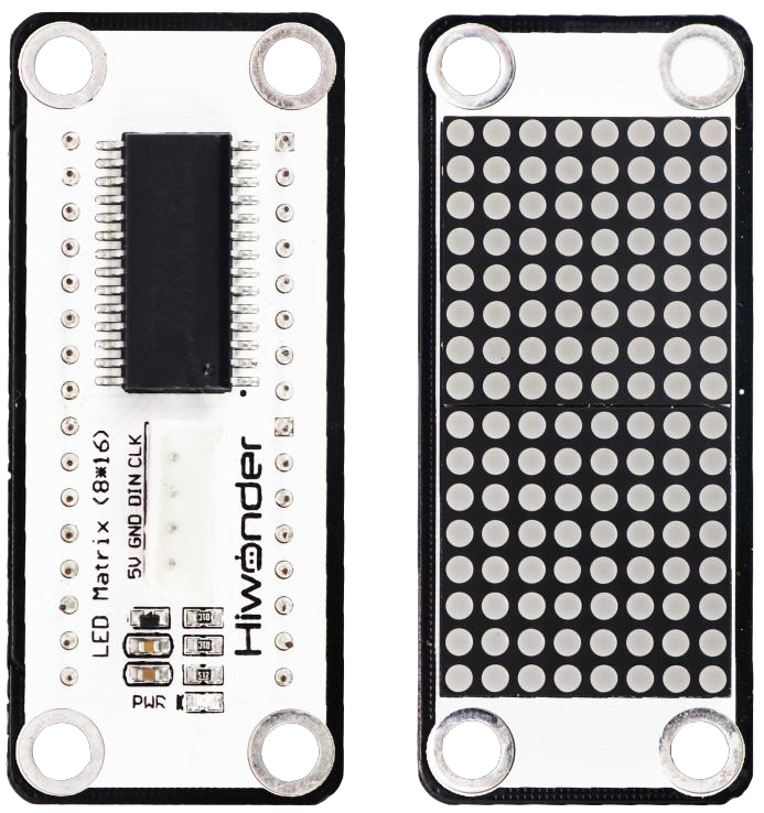
1.1.1 Sensor Introduction
LED dot matrix display module features high brightness, flicker-free display, and easy wiring. It can display numbers, text, and images.
It also includes LEGO-compatible holes for creative DIY designs.
1.1.2 Working Principle
The module consists of two red 8x8 LED lamp beads, which can control the dot matrix screen through the driver control chip TM640B.
The working principle of the LED matrix module can be summarized in four aspects:
Luminous characteristics of LED lamp beads: The dot matrix module uses the luminous characteristics of LED lamp beads to control the brightness of LED lamp beads to realize the display of graphics, numbers, letters, etc.
Row-column scanning driving method: The typical driving method of this module is row-column scanning. First, a specific row of LEDs is activated, then the LEDs that need to be lit in that row are controlled, and the process moves to the next row. This method effectively reduces driving complexity and cost, while achieving high refresh rates for smooth display effects.
Serial communication control: The module can also be controlled via serial communication, which requires the corresponding serial module and control program. Serial communication enables more flexible control, allowing the LED matrix module’s display content to be managed via a computer, smartphone, or other devices.
Internal wiring configuration: Matrix modules are classified into two types based on internal wiring: common anode and common cathode. In a common anode module, all the anodes of the LEDs are connected to the row lines; a column input of 1 turns the LED off, while 0 turns it on. In a common cathode module, the configuration is reversed: all the cathodes are connected to the row lines; a column input of 0 turns the LED off, and 1 turns it on.
In summary, the LED matrix module works by combining the four features described above to display and control graphics, numbers, letters, and other characters.
1.2 Notice
Do not exceed the rated voltage range during use.
Handle with care during use.
Avoid using the dot matrix module in high temperature or direct sunlight environments.
Avoid dust and moisture, as dust and humidity may affect the display performance of the LED matrix module.
1.3 Specifications
For more information of this chip, you may refer to “LED dot matrix module schematic”.
1.3.1 Pin Instruction
| Pin | Instruction |
| 5V | 5V |
| GND | Ground |
| DIN | Serial data input. Data changes when CLK is low and is transmitted when CLK is high. |
| CLK | Clock input, input data on the rising edge. |
1.3.2 Specifications
| Dot Matrix Module | |
| Parameter | Specification |
| Power Supply | DC 5V |
| Operating Current | 45mA |
| Dot Matrix Pixels | 8×16 |
| Dot Matrix Brightness | Adjustable 8 levels of brightness. |
| Connector Type | 5264-4W |
| Number of Pins | 4 |
| Indicator Light (PWR) Description | The PWR LED lights up when powered. |
| Product Dimensions | 56mmx24mm |
| Modular installation, compatible with Lego series. | |
1.4 Project Outcome
You can refer to the example tutorials and program demonstrations for each platform in the same directory as this tutorial.