2. Arduino Development Tutorial
2.1 Getting Started
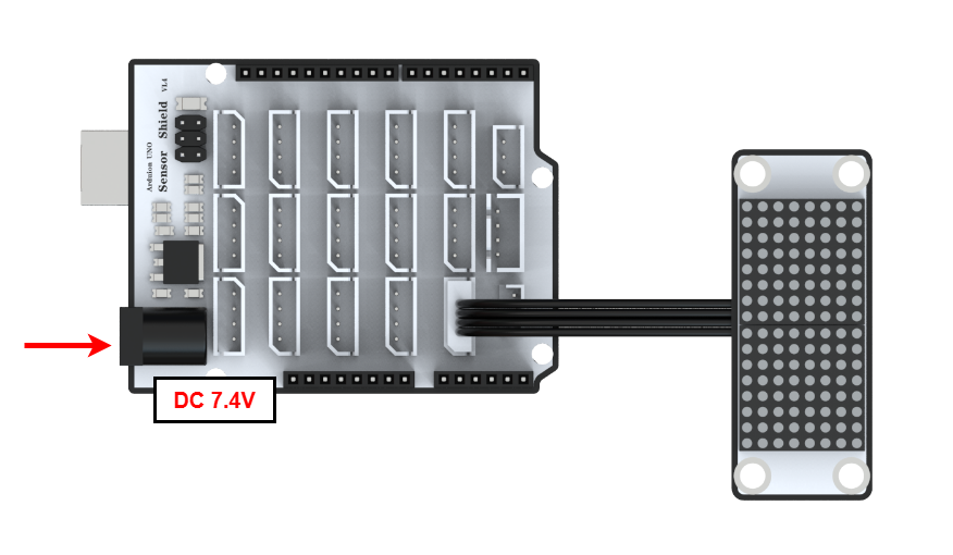
2.1.1 Wiring Instruction
This section illustrates connecting a 4-pin cable to the A2 and A3 ports on the Arduino expansion board. Refer to the diagram below.
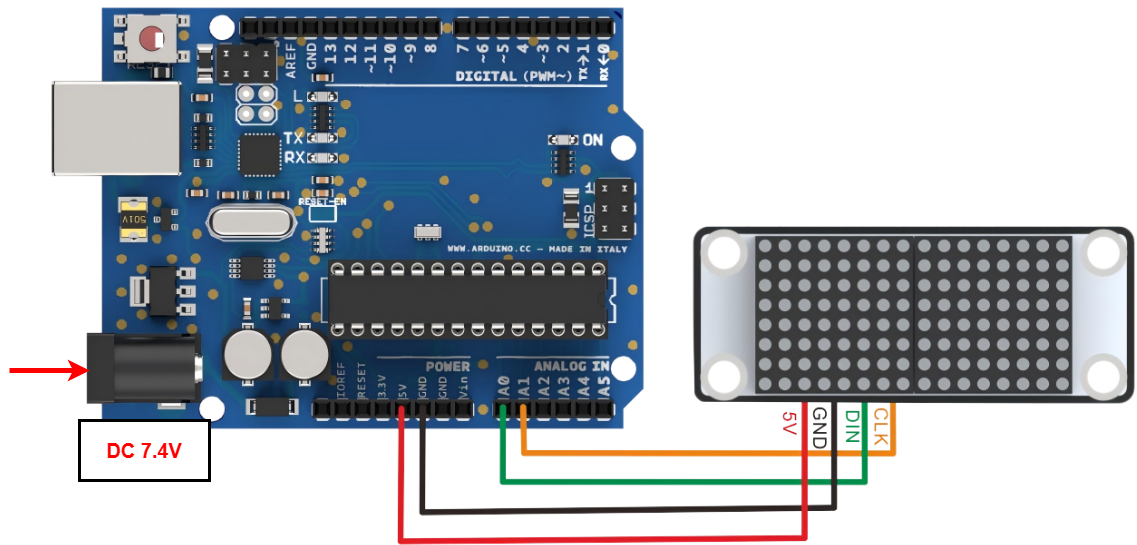
If you do not have an Arduino expansion board, use a Dupont wire to directly connect to the Arduino development board, just as below:
Note
When using Hiwonder’s lithium battery, connect the battery cable with the red wire to the positive (+) terminal and the black wire to the negative (–) terminal of the DC port.
If the battery is not connected to the cables, do not connect the cable ends directly together. Doing so may cause a short circuit and damage the system.
Before powering on, ensure that no metal objects are touching the controller. Otherwise, the exposed pins at the bottom of the board may cause a short circuit and damage the controller.
2.1.2 Environment Configuration
You can install the Arduino IDE on your computer. Download path: “Appendix-> Arduino Installation Package.” For detailed usage of the Arduino IDE, please refer to the documentation in the same directory.
2.2 Test Case
Program to display “Hello” on the LED matrix module.
2.2.1 Program Download
Connect the Arduino UNO development board with the expansion board to the computer via a USB cable. You can open the Arduino IDE, click “File->New”, and import the code in the same directory as this tutorial.
Remember to select the correct development board and port. The ports shown below are for reference only. Then compile and upload the program.

After the code is uploaded, click
 to open the serial monitor, set the baud rate to 9600 to observe the output.
2.2.2 Project Outcome
Program to display the text “Hello” on the LED matrix screen in a 1-second loop, while simultaneously printing “Hello” in the serial monitor.

2.2.3 Program Brief Analysis
Import Libraries
#include <Wire.h>
#include <Arduino.h>
#include <WMHead.h>
#include <WMBoard.h>

#define DIN A0  //Define DIN as A0
#define CLK A1 //Define CLK as A1
First, import the WMHHead.h library file, and then initialize the interface DIN to A0 and CLK to A1.
Initialization
WMMatrixLed matrixLed(CLK, DIN);//Initialization pin port, parameter 1 CLK is the clock pin, parameter 2 DIN is the signal input

unsigned char drawBuffer[16];//Display character array buffer
unsigned char *drawTemp;

void setup()
{
  Serial.begin(9600);
  matrixLed.setColorIndex(1);//Set Color
  matrixLed.setBrightness(10);//Set the brightness to 8 levels adjustable
}
Initialize the pin number and the display character array. Set the serial port baud rate to 9600, and set the color and brightness to 8 levels.
Loop Process
void loop() {
   drawTemp = new unsigned char[16]{
  0x00,0x00,0x00,0x0E,0x1F,0x3F,0x7F,0xFE,0xFE,0x7F,0x3F,0x1F,0x0E,0x00,0x00,0x00};

  memcpy(drawBuffer,drawTemp,16);
  free(drawTemp);

  matrixLed.drawBitmap(0,0,16,drawBuffer);//Display the contents of the drawBuffer array on the dot matrix screen
  Serial.println("Shape of hear");//Serial port print text display
  delay(1000);
In the loop() function, set the display format to hexadecimal. Store the character in the display buffer variable. Output the buffer variable to the LED dot matrix module, and finally, print the displayed character through the serial port.