4. Jetson Nano Development Tutorial
4.1 Getting Started
4.1.1 Wiring Instruction
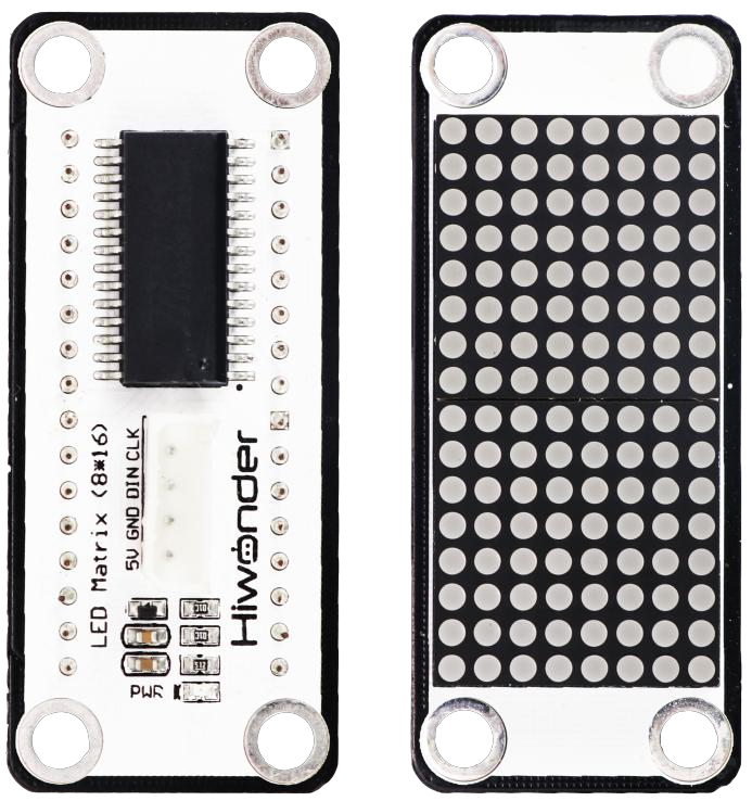
This section uses DuPont wires to connect LED dot Matrix Module. For wiring instructions, refer to the figure below:

Note
Before powering on, ensure that no metal objects are touching the controller. Otherwise, the exposed pins at the bottom of the board may cause a short circuit and damage the controller.
4.1.2 Environment Configuration
Install NoMachine on your computer. The software package is located under “2 Software Tools & Programs -> 01 Software Installation Package -> Remote Desktop Connection Tool -> 1 Remote Desktop Connection Tool”.
For detailed usage of NoMachine, refer to the materials in the same directory.
Drag the program and SDK library files into the Raspberry Pi system image, in this example, the files are placed on the Desktop for demonstration.
Note
Make sure the library files are placed in the same directory as the program.
Open the terminal and enter the command to navigate to the program directory, enter:
cd Desktop/
4.2 Test Case
In this case, control the GPIO pins to set high (turn on) or low (turn off) levels to make the dot matrix module display the characters “Hello”.
4.2.1 Program Execution
Open the terminal and enter the command to navigate to the program directory, enter:
cd Desktop/
Run the program by entering:
python3 tm1640_led_matrix.py
4.2.2 Project Outcome
The “Hello” character is shown on the dot matrix module.
4.2.3 Program Brief Analysis
Import Libraries
from tm1640 import TM1640
import time
Import the required libraries for the program, including tm1640, which is the library for the dot matrix module.
Display “Hello”
Assign a 16-byte list of dot matrix module to mtx.gram.
mtx.gram =(0x00,0x00,0x00,0x0E,0x1F,0x3F,0x7F,0xFE,0xFE,0x7F,0x3F,0x1F,0x0E,0x00,0x00,0x00)
As shown in the figure below:
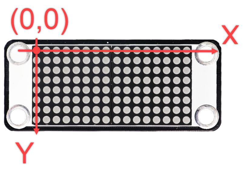
x: Horizontal LED index, numbered from 0 to 15 from left to right.
y: Vertical LED index, numbered from 0 to 7 from top to bottom.
gram is the core buffer in the TM1640 driver library used to store LED matrix display data.
Each element corresponds to the on/off state of a column of LEDs (16 columns in total, with horizontal LED indices x from 0 to 15; each column has 8 rows, with vertical LED indices y from 0 to 7, counted from top to bottom).
mtx.gram =(0x00,0x00,0x00,0x0E,0x1F,0x3F,0x7F,0xFE,0xFE,
0x7F,0x3F,0x1F,0x0E,0x00,0x00,0x00)
The 7th element (0th column) is 0x7f, which in binary is 01111111. The LED states from top to bottom in column 0 are: off, on, on, on, on, on, on, on.
The 2nd element (1st column) is 0x00, which in binary is 00000000. The LED states from top to bottom in column 1 are: off, off, off, off, off, off, off, off.
The remaining elements follow the same pattern.
Call the mtx.refresh method of the mtx object to display the contents of mtx.refresh on the LED dot matrix.
mtx.refresh()
Wait 1 second, then turn off the dot matrix display.
mtx.refresh()
        time.sleep(1)
        mtx.gram = [0] * 16