7. ROS+OpenCV Vision Projects
7.1 Color Threshold Adjustment
Objects may appear differently in color under various light sources, which can affect games involving color recognition. This lesson will guide you through using the LabConfig tool to adjust the color threshold and mitigate this issue effectively.
7.1.1 Enable LabConfig
Note
The input command should be case-sensitive, and keywords can be complemented using Tab key.
(1) Start ROSPug robot dog, and access the robot system desktop using NoMachine.
(2) Double-click  to start the
 LabConfig tool. If the software is enabled successfully, you can skip step (3) to (6).
(3) If LabConfig cannot be opened, double-click  to open the command-line terminal.
(4) Execute the command below:
roslaunch lab_config lab_config_manager.launch
(5) Run the following command, and hit Enter key to enable the camera service
roslaunch pug_peripherals camera.launch
(6) Double-click to open the LabConfig tool.
7.1.2 Introduction to LabConfig Interface
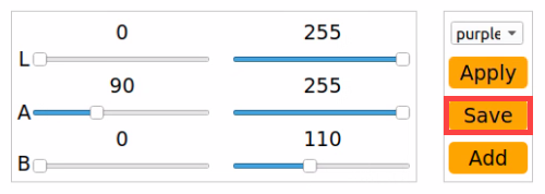
The LabConfig interface is divided into two parts, including display area and parameter adjustment area.
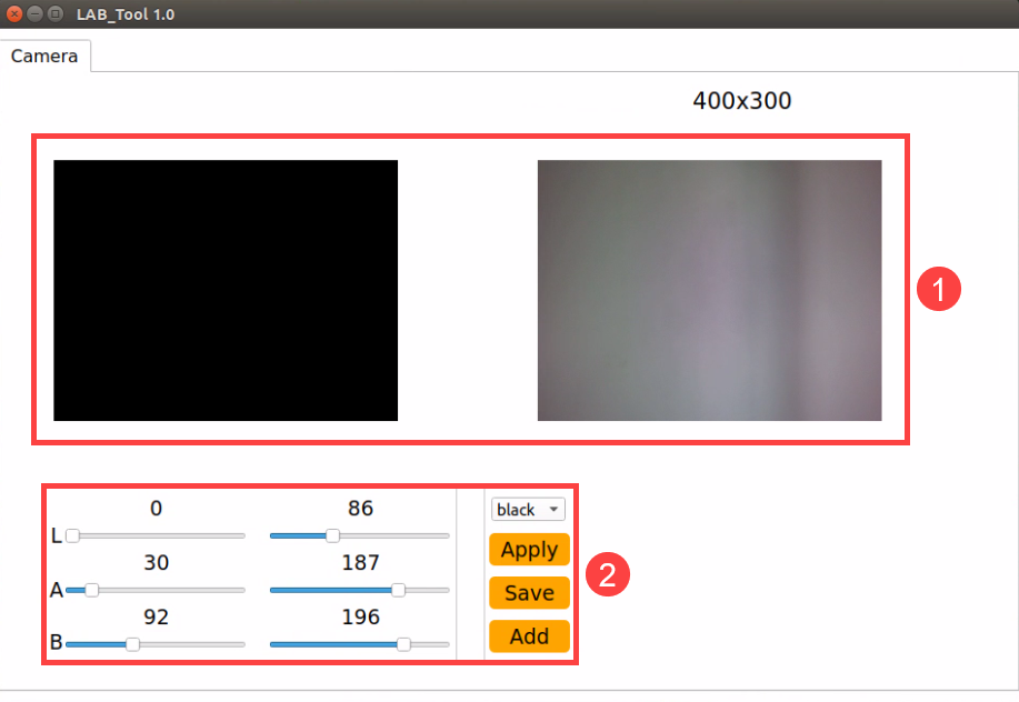
(1) Display area: The image on the left side is the camera-processed image, while the image on the right side is the original.
Note
If the live camera feed cannot be displayed properly, indicating a failure in camera connection, please ensure that the connection cable is securely plugged in.
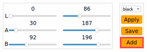
(2) Parameter adjustment area: adjust the color threshold parameters. The functions of the icons are listed below:
| Icon | Function |
|---|---|
 |
Drag the sliders L, A and B to adjust the L, A and B components of the live camera feed. |
 |
Select the color to be adjusted. |
 |
Apply the color threshold currently adjusted. |
 |
Save the adjustment result. |
 |
Add new colors to be recognized. |
7.1.3 Adjust Color Threshold
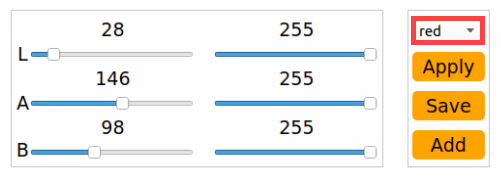
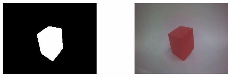
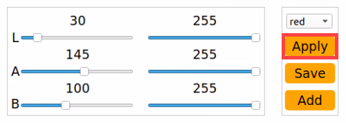
(1) Start LabConfig. Select the color to be adjusted in the drop-down menu. Take adjusting red as example.
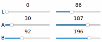
(2) Set the ‘min’ value of L, A and B components as ‘0’, and the ‘max’ values to ‘255’.
(3) Position the colored object within the camera’s field of view, consult the LAB color space distribution map, and fine-tune the L, A, and B components to align with the desired color recognition range.
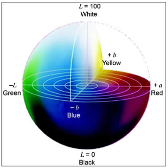
If the red hue is closer to ‘+a’, adjust by increasing the A component. This involves maintaining the ‘max’ value of the A component unchanged while increasing its ‘min’ value until the color object area on the left side of the screen turns white, while the remaining area turns black.
(4) Fine-tune the remaining L and B components based on the environmental conditions. If the red hue appears lighter, increase the ‘min’ value of the L component. Conversely, if the red hue appears darker, decrease the ‘max’ value of the L component. If the red hue appears warmer, increase the ‘min’ value of the B component; if it appears cooler, reduce the ‘max’ value of the B component.
The table below displays the parameter information for LAB threshold adjustment.
| Color component | Range | Color zone |
|---|---|---|
| L | 0~255 | Black-White(-L ~ +L) |
| A | 0~255 | Green-Red(-a ~ +a) |
| B | 0~255 | Blue-Yellow(-b ~ +b) |
(5) Click-on ‘Apply’ button to apply the color threshold parameters currently adjusted.
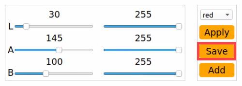
(6) Click the “Save” button to preserve the color threshold adjustment parameters.
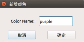
7.1.4 Add New Recognition Color
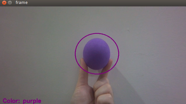
In addition to the three pre-defined recognition colors, users have the option to add other identifiable colors. Here, purple will be used as an example. The specific steps are as follows:
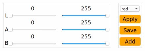
(1) Open LabConfig, then click-on ‘Add’ button.
(2) Name the color, for example ‘purple’.
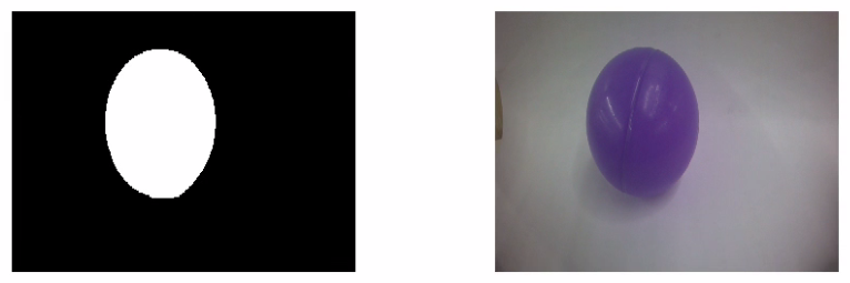
(3) Position the colored object within the camera’s field of view, then adjust the L, A, and B component sliders until the color object area on the left side of the screen turns white, while the remaining areas turn black.
Note
To access the detailed instructions, please refer to section 7.1.3 Adjust Color Threshold.
(4) Click the ‘Apply’ button to apply the currently adjusted color threshold parameters.
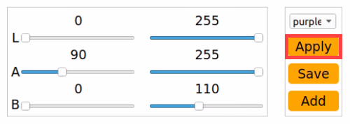
(5) Click-on ‘Save’ button to save the the currently adjusted color threshold parameters.
7.2 Color Recognition
Note
If color recognition is inaccurate, please refer to 7.1 Color Threshold Adjustment for further adjustments.
Ensure there are no other objects in the camera’s field of view that contain the recognized color, as this may affect gameplay effectiveness.
7.2.1 Program Logic
First, the color must be identified. To achieve this, we utilize the Lab color space for processing, converting the image color space from RGB to Lab. Subsequently, operations such as binarization, erosion, and dilation are applied to the image to extract the maximum contour containing the target color. Finally, the color recognition results are provided back through both the display screen and the terminal interface.
7.2.2 Operation Steps
Note
The input command should be case sensitive.
(1) Start ROSPug robot dog, and access the robot system desktop using NoMachine.
(2) Click-on  to open the command-line terminal.
(3) Execute the following command, and hit Enter key to initiate the color recognition program.
rosrun pug_example color_detect_demo.py
(4) If you need to terminate this program, use short-cut ‘Ctrl+C’. If the program cannot be stopped, please retry.
7.2.3 Program Outcome
When red, green, or blue is recognized, the color name will be printed in the lower left corner of the screen and also displayed in the terminal. Additionally, the target item will be highlighted with a circle of the corresponding color on the screen.
Take recognizing red sphere as example.
7.2.4 Program Parameters Explanation
The source code of this program is saved in: /home/pug/src/pug_example/scripts/detect_and_track/color_detect_demo.py
Image Processing
(1) Gaussian Filtering
Before converting the image color space from RGB to Lab, it undergoes denoising. The GaussianBlur() function from the cv2 library is employed for this purpose, performing Gaussian filtering on the image.
53 | frame_gb = cv2.GaussianBlur(frame_resize, (3, 3), 3) |
The parameters in the function brackets are as follows:
The first parameter, frame_resize, represents the input image.
The second parameter, (3, 3), denotes the Gaussian kernel size.
The third parameter, 3, indicates the variance allowed around the mean value in Gaussian filtering. A larger value allows greater variance around the mean, while a smaller value allows less variance around the mean.
(2) Thresholding Processing
Utilize inRange() function from cv2 library to perform thresholding on the image.
61 62 63 64 65 66 67 68 | if i in ['red', 'green', 'blue', 'purple']: frame_mask = cv2.inRange(frame_lab, (color_range_list[i]['min'][0], color_range_list[i]['min'][1], color_range_list[i]['min'][2]), (color_range_list[i]['max'][0], color_range_list[i]['max'][1], color_range_list[i]['max'][2])) |
The first parameter in the function brackets represents the input image. The second and third parameters denote the lower and upper limits of the threshold, respectively. When the RGB color value of a pixel falls within the specified range, the pixel is assigned a value of 1; otherwise, it is assigned a value of 0.
(3) Erosion and Dilation
To reduce interference and achieve smoother images, erosion and dilation operations are applied.
69 70 | eroded = cv2.erode(frame_mask, cv2.getStructuringElement(cv2.MORPH_RECT, (3, 3))) dilated = cv2.dilate(eroded, cv2.getStructuringElement(cv2.MORPH_RECT, (3, 3))) |
The erode() function performs erosion operations on images. In the code example eroded = cv2.erode(frame_mask, cv2.getStructuringElement(cv2.MORPH_RECT, (3, 3))), the parameters in the brackets have the following meanings:
The first parameter, frame_mask, represents the input image.
The second parameter, cv2.getStructuringElement(cv2.MORPH_RECT, (3, 3)), defines the structural element or kernel that determines the operation’s nature. The first parameter within parentheses specifies the kernel shape, and the second parameter specifies the kernel size.
Similarly, the dilate() function is used to dilate images. The parameters in its parentheses have the same meanings as those in the erode() function.
(4) Obtain the Contour with The Maximum Area
Upon completing the aforementioned image processing, the next step involves obtaining the contour of the recognized target, which utilizes the findContours() function in the cv2 library. The parameters within the function brackets are as follows:
71 | contours = cv2.findContours(dilated, cv2.RETR_EXTERNAL, cv2.CHAIN_APPROX_NONE)[-2] |
① The first parameter represents the input image.
② The second parameter denotes the contour retrieval mode.
③ The third parameter specifies the contour approximation method.
Identify the contour with the largest area among the contours obtained. To minimize interference, a minimum threshold value must be set. Only when the area exceeds this threshold is the target contour considered valid.
37 38 | if contour_area_temp > 50: area_max_contour = c |
(5) Feedback Information
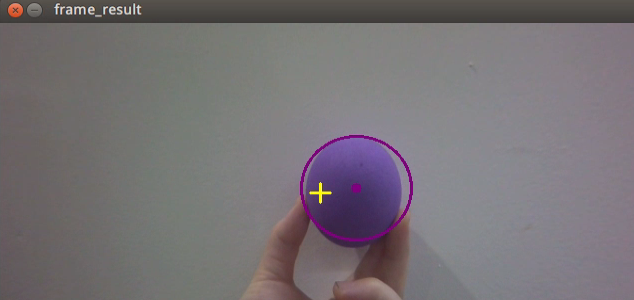
After obtaining the contour with the maximum area, the recognition target is highlighted with a circle using the circle() function from the cv2 library. The circle’s color corresponds to the recognition color.
83 | cv2.circle(img, (centerX, centerY), radius, range_rgb[color_area_max], 2) |
Display the detected color on the returned image, using the putText() function from the cv2 library.
{lineno-start=}
cv2.putText(img, "Color: " + detect_color, (10, img.shape[0] - 10), cv2.FONT_HERSHEY_SIMPLEX, 0.65, draw_color, 2)

The parameters within the function brackets have the following meanings:
① The first parameter, img, represents the input image.
② The second parameter, ("Color: " + detect_color), specifies the content to be displayed.
③ The third parameter, (10, img.shape[0] - 10), determines the display position.
④ The fourth parameter, cv2.FONT_HERSHEY_SIMPLEX, defines the font type.
⑤ The fifth parameter, 0.65, indicates the font size.
⑥ The sixth parameter, draw_color, represents the font color.
⑦ The seventh parameter, 2, signifies the font thickness.
7.3 Color Localization & Tracking
Note
Please ensure that objects with the same or similar color as the one being tracked are not present within the camera’s field of view, as this may affect game.
During tracking, ensure that the color block does not move too quickly.
If color recognition accuracy is unsatisfactory, refer to 7.1 Color Threshold Adjustment for guidance on adjustments.
The object is tracked using images captured by a high-definition camera. When the target color block is positioned within the camera’s field of view, the leg servos will adjust their position to mimic the movement of the target color block.
7.3.1 Program Logic
The camera captures an RGB image, which is then resized and processed with Gaussian blur. The image’s color space is converted from RGB to LAB (for more details on the LAB color space, refer to OpenCV Computer Vision Course->Image Processing—Color Space Conversion.
Next, the color thresholds set in 7.1 Color Threshold Adjustment are used to match the image. Once the colors are detected, a morphological opening operation is applied, and the detected colors are highlighted with circles.
Opening Operation: Erosion followed by dilation. This removes small objects, smooths shape boundaries, and preserves the object’s area. It also eliminates small noise particles and separates connected objects.
Erosion: Reduces the boundary points of objects, causing the boundary to shrink inward, and removes objects smaller than the structuring element.
Dilation: Expands the boundary of objects, merging background points into the object and causing the boundary to expand outward.
Finally, the center of the color block is calculated based on the circle’s position. The positional deviation between the color block’s center and the image center is then determined. A PID algorithm is used to adjust the robot in real-time, allowing the gimbal servo to follow the movement of the color block.
7.3.2 Operation Steps
Note
The input command should be case sensitive, and keywords can be complemented using Tab key.
(1) Start ROSPug robot dog, and access the robot system desktop using NoMachine.
(2) Click-on  to open the command-line terminal.
(3) Execute the following command, and hit Enter key to initiate the color tracking program.
rosrun pug_example color_tracking_demo.py
(4) If you need to terminate this program, use short-cut ‘Ctrl+C’. If the program cannot be stopped, please retry.
7.3.3 Program Outcome
After activating the mode, position the purple ball in front of the HD camera. The returned image will show the detected color of the target, and the robot dog will track and follow the target’s vertical movements.
7.3.4 Code Analysis
The source code of this program is saved in :/home/pug/src/pug_example/scripts/detect_and_track/color_tracking_demo.py
Import Function Library
1 2 3 4 5 6 7 8 9 10 11 | #!/usr/bin/env python3 # encoding: utf-8 import cv2 import math import time import rospy import numpy as np from pug_sdk import pid, common from pug_control.msg import Pose from sensor_msgs.msg import Image from pug_control.srv import SetActionName |
(1) cv2: OpenCV library used for image processing.
(2) rospy: ROS Python client library for node communication.
(3) numpy: Library for numerical computations.
(4) pid & common: Custom PID controller and utility functions.
(5) Pose, Image, SetActionName: ROS message and service types.
Global Variable Definition
13 14 15 16 17 18 19 | size = (320, 180) target_color = '' color_range = None pose_pub = None y_dis = 0 y_pid = pid.PID(P=0.0003, I=0, D=0) |
Color Mapping Table
21 22 23 24 25 26 27 28 | range_rgb = { 'red': (0, 0, 255), 'blue': (255, 0, 0), 'green': (0, 255, 0), 'black': (0, 0, 0), 'white': (255, 255, 255), 'purple': (255, 0, 255), } |
Map color names to corresponding BGR values for visualization.
def run(img) Function
This is the main processing function, which performs the following operations:
(1) Image Preprocessing
55 56 | frame_resize = cv2.resize(img_copy, size, interpolation=cv2.INTER_NEAREST) frame_lab = cv2.cvtColor(frame_resize, cv2.COLOR_BGR2LAB) |
① Resize the image to improve processing efficiency.
② Convert the image to LAB color space, which is more suitable for color recognition.
(2) Color Recognition and Contour Extraction
63 64 65 66 67 | frame_mask = cv2.inRange(frame_lab, tuple(target_color_range['min']), tuple(target_color_range['max'])) eroded = cv2.erode(frame_mask, cv2.getStructuringElement(cv2.MORPH_RECT, (3, 3))) dilated = cv2.dilate(eroded, cv2.getStructuringElement(cv2.MORPH_RECT, (3, 3))) contours = cv2.findContours(dilated, cv2.RETR_EXTERNAL, cv2.CHAIN_APPROX_NONE)[-2] area_max_contour, area_max = getAreaMaxContour(contours) |
① Use a mask to extract regions of a specific color.
② Apply morphological operations (erosion and dilation) to reduce noise.
③ Detect and filter contours, selecting the largest one as the target.
(3) Target Localization and Feedback Control
69 70 71 72 73 74 75 76 77 78 79 80 81 82 83 84 85 | if area_max > 100: (center_x, center_y), radius = cv2.minEnclosingCircle(area_max_contour) center_x = int(common.val_map(center_x, 0, size[0], 0, img_w)) center_y = int(common.val_map(center_y, 0, size[1], 0, img_h)) radius = int(common.val_map(radius, 0, size[0], 0, img_w)) if radius > 100: return img cv2.circle(img, (int(center_x), int(center_y)), int(radius), range_rgb[target_color], 2) cv2.circle(img, (int(center_x), int(center_y)), 5, range_rgb[target_color], -1) y_pid.SetPoint = img_h / 2.0 y_pid.update(center_y) y_dis += y_pid.output y_dis = np.radians(20) if y_dis > np.radians(20) else y_dis y_dis = np.radians(-20) if y_dis < np.radians(-20) else y_dis pose_pub.publish(0, y_dis, 0, -0.13, 0, 0, 0, 0) |
① Determine the center coordinates of the target.
② Use a PID controller to calculate the pitch angle.
③ Publish posture commands to the robot control system.
Image Callback Function
98 99 100 101 102 103 104 105 106 107 108 109 110 111 112 113 114 | if __name__ == '__main__': rospy.init_node('color_tracking_demo', log_level=rospy.INFO) pose_pub = rospy.Publisher('/pug_control/pose', Pose, queue_size=1) rospy.Subscriber('/csi_camera/image_rect_color', Image, image_callback) color_range = rospy.get_param('/lab_config_manager/color_range_list', {}) run_action_group_srv = rospy.ServiceProxy('/pug_control/run_action_group', SetActionName) time.sleep(0.1) run_action_group_srv('stand') target_color = 'purple' try: rospy.spin() except KeyboardInterrupt: rospy.loginfo("Shutting down") finally: cv2.destroyAllWindows() |
(1) Initialize the ROS node.
(2) Set the target color to purple.
(3) Start the service call and subscribe to the image topic.
(4) Enter the ROS main loop using rospy.spin().
7.4 KCF Target Tracking
Note
Make sure to keep the object within the camera’s view, and avoid moving too quickly. If the object goes out of the camera’s range, tracking will stop. To resume tracking, simply reselect the object.
In this lesson, we will employ the KCF algorithm to use the mouse to frame the target. The ROSPug robot dog will then identify and frame the target, displaying its coordinates on the terminal.
7.4.1 Introduction to KCF
KCF (Kernel Correlation Filter) is an algorithm proposed by Joao F. Henriques, Rui Caseiro, Pedro Martins, and Jorge Batista in 2014. It is a discriminative tracking method that utilizes the cyclic matrix of the area surrounding the target to gather positive and negative samples. These samples are then used to train a target detector. This detector is employed to determine if the predicted position in the next frame matches the target. Based on this detection, the training set and consequently the object detector are updated.
7.4.2 Program Logic
First, build a tracker using OpenCV’s KCF object tracking algorithm and subscribe to topic messages to receive the real-time camera feed.
Next, use a mouse callback function to select the tracking target in the returned image. The tracker will then provide the real-time position of the target, which is updated using a PID algorithm.
Finally, control the ROSPug to track the target vertically based on its position.
7.4.3 Operation Steps
Note
The input command should be case sensitive, and keywords can be complemented using Tab key.
(1) Start the robot dog, and access the robot system desktop using NoMachine.
(2) Double-click  to open the command-line terminal.
(3) Execute the following command and hit Enter key to disable the auto-start service.
rosrun pug_example kcf_tracking.py
(4) If you need to terminate the program, use short-cut ‘Ctrl+C’ to stop the program.
7.4.4 Program Outcome
After starting the game, position the target tracking object within the camera’s field of view. Press ‘s’ and use the left mouse button to select it on the screen. While selecting, the chosen area will be highlighted with a blue box. Release the left mouse button and press ‘Space’ or ‘Enter’ on the keyboard to confirm the selection; the box will turn green, indicating tracking can begin. If you need to reselect the tracking target, right-click the mouse on the screen to clear it, then repeat the selection process as described above.
7.4.5 Program Analysis
The source code is saved in : /home/pug/src/pug_example/scripts/detect_and_track/kcf_tracking.py
**Initialize Configuration: init **
16 17 18 19 20 21 22 23 24 25 26 27 28 29 30 31 32 33 34 35 36 37 38 39 40 41 42 43 44 45 46 | def __init__(self, name): rospy.init_node(name) self.name = name self.y_dis = 0 self.y_pid = pid.PID(P=0.0005, I=0, D=0) self.image_queue = queue.Queue(maxsize=2) self.fps = FPS() signal.signal(signal.SIGINT, self.shutdown) self.running = True self.mouse_click = False self.selection = None self.track_window = None self.drag_start = None self.start_circle = True self.start_click = False self.params = cv2.TrackerNano_Params() model_path = os.path.split(os.path.realpath(__file__))[0] self.params.backbone = os.path.join(model_path, 'nanotrack_backbone_sim.onnx') self.params.neckhead = os.path.join(model_path, 'nanotrack_head_sim.onnx') self.tracker = cv2.TrackerNano_create(self.params) cv2.namedWindow(name, 1) cv2.setMouseCallback(name, self.onmouse) self.image_sub = rospy.Subscriber("/csi_camera/image_rect_color", Image, self.image_callback, queue_size=1) self.pose_pub = rospy.Publisher('/pug_control/pose', Pose, queue_size=1) self.run_action_group_srv = rospy.ServiceProxy('/pug_control/run_action_group', SetActionName) time.sleep(0.2) self.run_action_group_srv('stand') self.run() |
(1) Initialize the ROS node and related parameters (e.g., PID controller, image queue).
(2) Load the NanoTrack model file (in ONNX format) for object tracking.
(3) Create an image display window and bind a mouse event callback function.
(4) Subscribe to the image topic /csi_camera/image_rect_color.
(5) Publish posture information to /pug_control/pose.
(6) Call the service /pug_control/run_action_group to control the action group.
Image Callback Function: image_callback
52 53 54 55 56 57 58 59 | def image_callback(self, ros_image: Image): rgb_image = np.ndarray(shape=(ros_image.height, ros_image.width, 3), dtype=np.uint8, buffer=ros_image.data) if self.image_queue.full(): self.image_queue.get() self.image_queue.put(rgb_image) |
(1) Receives ROS image messages and places them into the image queue.
(2) Uses queue.Queue to buffer image data and prevent accumulation caused by processing delays.
Mouse Event Processing: onmouse
62 63 64 65 66 67 68 69 70 71 72 73 74 75 76 77 78 79 80 81 82 83 84 85 86 | def onmouse(self, event, x, y, flags, param): if event == cv2.EVENT_LBUTTONDOWN: self.mouse_click = True self.drag_start = (x, y) self.track_window = None if self.drag_start: xmin = min(x, self.drag_start[0]) ymin = min(y, self.drag_start[1]) xmax = max(x, self.drag_start[0]) ymax = max(y, self.drag_start[1]) self.selection = (xmin, ymin, xmax, ymax) if event == cv2.EVENT_LBUTTONUP: self.mouse_click = False self.drag_start = None self.track_window = self.selection self.selection = None if event == cv2.EVENT_RBUTTONDOWN: self.mouse_click = False self.selection = None self.track_window = None self.drag_start = None self.start_circle = True self.start_click = False self.run_action_group_srv('stand') self.tracker = cv2.TrackerNano_create(self.params) |
Allows the user to select the target area by drawing a box in the image window using the mouse.
Image Processing: image_proc
88 89 90 91 92 93 94 95 96 97 98 99 100 101 102 103 104 105 106 107 108 109 110 111 112 113 114 115 116 117 118 119 120 121 122 123 124 125 126 127 128 129 130 131 | def image_proc(self, image): if self.start_circle: if self.track_window: cv2.rectangle(image, (self.track_window[0], self.track_window[1]), (self.track_window[2], self.track_window[3]), (0, 0, 255), 2) elif self.selection: cv2.rectangle(image, (self.selection[0], self.selection[1]), (self.selection[2], self.selection[3]), (0, 0, 255), 2) if self.mouse_click: self.start_click = True if self.start_click: if not self.mouse_click: self.start_circle = False if not self.start_circle: print('start tracking') bbox = (self.track_window[0], self.track_window[1], self.track_window[2] - self.track_window[0], self.track_window[3] - self.track_window[1]) self.tracker.init(image, bbox) else: ok, box = self.tracker.update(image) if ok and min(box) > 0: p1 = (int(box[0]), int(box[1])) p2 = (int(p1[0] + box[2]), int(p1[1] + box[3])) cv2.rectangle(image, p1, p2, (0, 255, 0), 2, 1) center_y = (p1[1] + p2[1]) / 2 img_h, img_w = image.shape[:2] self.y_pid.SetPoint = img_h / 2.0 self.y_pid.update(center_y) self.y_dis += self.y_pid.output self.y_dis = np.radians(20) if self.y_dis > np.radians(20) else self.y_dis self.y_dis = np.radians(-20) if self.y_dis < np.radians(-20) else self.y_dis self.pose_pub.publish(0, self.y_dis, 0, -0.13, 0, 0, 0, 0) else: # Tracking failure cv2.putText(image, "Tracking failure detected !", (10, 460), cv2.FONT_HERSHEY_SIMPLEX, 0.6, (255, 255, 0), 1) self.fps.update() result_image = self.fps.show_fps(image) return result_image |
(1) Display the currently selected target region.
(2) Use the KCF algorithm to track the target.
(3) If tracking is successful, calculate the target’s center position and adjust the robot’s posture using the PID controller.
(4) If tracking fails, display the message “Tracking failure detected!”
Main Loop: run
133 134 135 136 137 138 139 140 141 142 143 144 | def run(self): while self.running: image = self.image_queue.get(block=True) try: result_image = self.image_proc(np.copy(image)) except BaseException as e: print(e) result_image = image cv2.imshow(self.name, cv2.cvtColor(result_image, cv2.COLOR_RGB2BGR)) cv2.waitKey(1) self.run_action_group_srv('stand') rospy.signal_shutdown('shutdown') |
(1) Continuously retrieve images from the image queue for processing and display the results. (2) Listen for the SIGINT signal (Ctrl+C) to gracefully shut down the node and perform cleanup operations.
7.5 Autonomous Line Following
7.5.1 Program Logic
Line following is a common challenge in robot competitions. While traditional methods often rely on two or four-channel sensors, the ROSPug robot achieves autonomous line following using its visual module to detect line colors and process images.
The process begins with identifying the line color using the Lab color space. The image is converted from RGB to Lab and then processed with binarization, erosion, and dilation to isolate the contours of the target color, which are highlighted with rectangles.
Once the color is recognized, the robot uses image feedback to calculate the line’s position. It then adjusts the ROSPug’s movement to follow the line and displays the line coordinates on the terminal, enabling effective autonomous line-following.
7.5.2 Operation Steps
Note
The input command should be case and space sensitive.
(1) Start the robot dog, and access the robot system desktop using NoMachine.
(2)  Double-click to open the command-line terminal.
(3) Execute the command to terminate the app auto-start service.
rosrun pug_example visual_patrol_demo.py
(4) If you need to terminate this game, press ‘Ctrl+C’ on the terminal. If the program cannot be stopped, please retry.
7.5.3 Program Outcome
Note
The default detection color is black.
Use black electrical tape to set a path, and put ROSPug on the black line. After initiating the game, the robot dog will move along the black line.
7.5.4 Function Extension
Change Followed Color
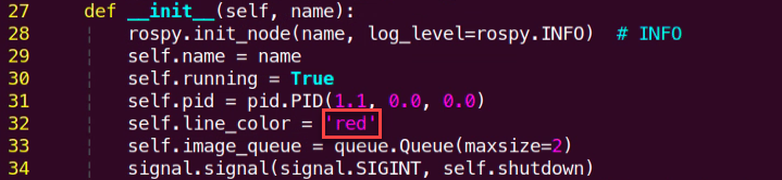
By default, the line-following color is set to black. To change the line-following color to a different one, such as red, please follow these steps:
(1) Execute the command and hit Enter key to edit the autonomous line following program.
vim visual_patrol_demo.py
(2) Locate the code as indicated in red frame below.
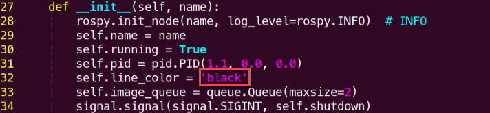
(3) Press ‘i’ key to enter the editing mode, then change ‘black’ to ‘red’. After modification, press ‘Esc’ key, input ‘:wq’ and press Enter key to save and exit the editing.
(4) Run the following command to initiate the game, and check the game effect.
rosrun pug_example visual_patrol_demo.py
7.5.5 Program Parameter Analysis
The source code of this program is saved in: /home/hiwonder/pug/src/pug_example/scripts/almighty_functions/visual_patrol_demo.py
Subscribe to a Publishing Topic
38 39 40 41 42 43 44 45 46 | self.image_sub = rospy.Subscriber("/csi_camera/image_rect_color", Image, self.image_callback, queue_size=1) self.pose_pub = rospy.Publisher('/pug_control/pose', Pose, queue_size=1) self.gait_pub = rospy.Publisher('/pug_control/gait', Gait, queue_size=1) self.cmd_vel_pub = rospy.Publisher('/cmd_vel', Twist, queue_size=10) self.run_action_group_srv = rospy.ServiceProxy('/pug_control/run_action_group', SetActionName) time.sleep(0.1) self.gait_pub.publish(0.2, 0.15, 0.0, 0.05) self.pose_pub.publish(0, math.radians(-18), 0, -0.13, 0, 0, 0, 0.5) self.run() |
(1) Subscribe to the camera topic /csi_camera/image_rect_color to receive images.
(2) Publish pose messages to the topic /pug_control/pose and gait messages to the topic /pug_control/gait.
(3) Publish velocity messages to the topic /cmd_vel.
Image Processing
The image is processed using OpenCV library functions to extract the contours of the color to be recognized. Then, the center point coordinates of the detected target are calculated.
90 91 92 93 94 95 96 97 98 99 100 101 102 103 104 105 106 107 108 109 110 111 112 113 114 115 116 117 118 119 120 121 122 123 | for r in self.roi: roi_h = self.roi_h_list[n] blobs = frame_gb[r[0]:r[1], r[2]:r[3]] frame_lab = cv2.cvtColor(blobs, cv2.COLOR_BGR2LAB) n += 1 if self.line_color in self.lab_data: frame_mask = cv2.inRange(frame_lab, (self.lab_data[self.line_color]['min'][0], self.lab_data[self.line_color]['min'][1], self.lab_data[self.line_color]['min'][2]), (self.lab_data[self.line_color]['max'][0], self.lab_data[self.line_color]['max'][1], self.lab_data[self.line_color]['max'][2])) opened = cv2.morphologyEx(frame_mask, cv2.MORPH_OPEN, np.ones((6, 6), np.uint8)) closed = cv2.morphologyEx(opened, cv2.MORPH_CLOSE, np.ones((6, 6), np.uint8)) contours = cv2.findContours(closed, cv2.RETR_EXTERNAL, cv2.CHAIN_APPROX_TC89_L1)[-2] max_contours = self.getAreaMaxContour(contours)[0] if max_contours is not None: rect = cv2.minAreaRect(max_contours) box = np.int0(cv2.boxPoints(rect)) for i in range(4): box[i, 1] = int(box[i, 1] + (n - 1) * roi_h + self.roi[0][0]) cv2.drawContours(image, [box], -1, (0, 0, 255, 255), 2) pt1_x, pt1_y = box[0, 0], box[0, 1] pt3_x, pt3_y = box[2, 0], box[2, 1] center_x, center_y = (pt1_x + pt3_x) / 2, (pt1_y + pt3_y) / 2 cv2.circle(image, (int(center_x), int(center_y)), 5, (0, 0, 255), -1) center_.append([center_x, center_y]) centroid_x_sum += center_x * r[4] weight_sum += r[4] |
Movement Control
Calculate the forward and turning speeds based on the center point coordinates, then publish velocity messages to control the movement of the machine.
{lineno-start=}
twist = Twist()
twist.linear.x = 0.15
if weight_sum is not 0:
line_centerx = int(centroid_x_sum / weight_sum)
deflection_angle = -math.atan((line_centerx - (img_w / 2.0)) / (img_h / 2.0))/2
# print(deflection_angle)
# self.pid.SetPoint = 0.138
self.pid.update(deflection_angle)
twist.angular.z = common.set_range(-self.pid.output, -1.0, 1.0)
self.cmd_vel_pub.publish(twist)
7.6 Autonomous Ball Shooting
7.6.1 Program Logic
Initialize the robot dog object, load the color threshold configuration file, define basic postures such as standing and bending, as well as gait parameters. Control the robot dog’s movement in a thread, adjusting its advancement based on the recognized position of color blocks to move left and right.
Next, the main thread continuously loops to capture images, recognizing color blocks within the images, and passing them to the motion control thread. The camera captures the image, adjusts it to a suitable resolution, converts it to the LAB color space for color threshold segmentation, and identifies the contour with the largest area as the target. The center coordinates of its minimum circumscribed circle are obtained.
Finally, the robot dog moves towards the target position. Upon reaching the target, it transitions to the hitting state, adjusts its position as necessary, performs the hitting action, then transitions to the end state and exits the program. Key functions and classes utilized include Camera, color threshold processing, contour detection, and more. The primary objective is to control the robot dog’s movement through color recognition to accomplish a simple ball delivery task. Colors, motion control logic, etc. can be customized as needed.
7.6.2 Operation Steps
Note
The input command should be case and space sensitive.
(1) Start the robot dog, and access the robot system desktop using NoMachine.
(2)  Double-click to open the command-line terminal.
(3) Execute the command below to terminate the app auto-start service.
rosrun pug_example kick_ball_demo.py
(4) If you need to terminate this game, press ‘Ctrl+C’ on the terminal. If the program cannot be stopped, please retry.
7.6.3 Program Outcome
Note
The default detection color is purple.
Place the required balls on the field and position the ROSPug robot dog on the field, ensuring that the balls are within the camera’s field of view. The distance between the balls and the robot should not exceed 1 meter.
7.6.4 Function Extension
Change Followed Color
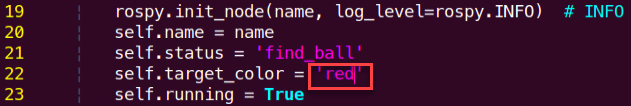
By default, the system recognizes the ball color as purple. If you need to change the recognized color, for example to red, please follow these steps:
(1) Execute the command vim kick_ball_demo.py and hit Enter key to edit the ball shooting program.
vim kick_ball_demo.py
(2) Locate the code as indicated in red frame below.
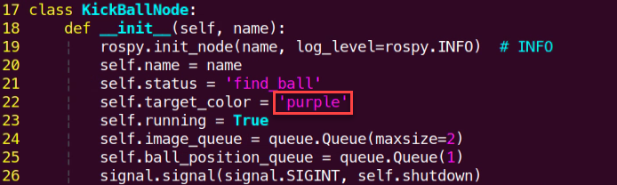
(3) Press the “i” key to enter editing mode, then change “purple” to “red”. Once the modification is complete, press the “Esc” key. Next, enter “:wq” and press Enter to save and exit.
(4) To initiate the independent kicking game, enter the following command. You can restart the game to view the updated effects.
rosrun pug_example kick_ball_demo.py
7.6.5 Program Parameter Analysis
The source code of this program is saved in:/home/hiwonder/pug/src/pug_example/scripts/almighty_functions/kick_ball_demo.py
Subscribe to Publishing Topic
30 31 32 33 34 35 | self.image_sub = rospy.Subscriber("/csi_camera/image_rect_color", Image, self.image_callback, queue_size=1) self.pose_pub = rospy.Publisher('/pug_control/pose', Pose, queue_size=1) self.gait_pub = rospy.Publisher('/pug_control/gait', Gait, queue_size=1) self.velocity_pub = rospy.Publisher('/pug_control/velocity_move', Velocity, queue_size=1) self.run_action_group_srv = rospy.ServiceProxy('/pug_control/run_action_group', SetActionName) time.sleep(0.1) |
(1) Subscribe to the camera topic /csi_camera/image_rect_color to receive images.
(2) Publish pose messages to the topic /pug_control/pose and gait messages to the topic /pug_control/gait.
Ball Recognition
Run image processing in the main thread to obtain the ball’s coordinate information and print it to the terminal. Then, use the ball’s center coordinates to control the robot dog to track the ball, as shown in the figure below:
111 112 113 114 115 116 117 118 119 120 121 122 123 124 125 126 127 128 129 130 131 132 133 134 135 136 137 138 139 140 141 142 143 144 145 146 |
def run(self):
while self.running:
image = self.image_queue.get(block=True)
if self.status == 'find_ball' or self.status == 'kick_ball':
GaussianBlur_img = cv2.GaussianBlur(image, (3, 3), 3)
frame_lab = cv2.cvtColor(GaussianBlur_img, cv2.COLOR_BGR2LAB)
frame_mask = cv2.inRange(frame_lab,
(self.lab_data[self.target_color]['min'][0],
self.lab_data[self.target_color]['min'][1],
self.lab_data[self.target_color]['min'][2]),
(self.lab_data[self.target_color]['max'][0],
self.lab_data[self.target_color]['max'][1],
self.lab_data[self.target_color]['max'][2]))
            eroded = cv2.erode(frame_mask, cv2.getStructuringElement(cv2.MORPH_RECT, (3, 3)))
            dilated = cv2.dilate(eroded, cv2.getStructuringElement(cv2.MORPH_RECT, (3, 3)))
contours = cv2.findContours(dilated, cv2.RETR_EXTERNAL, cv2.CHAIN_APPROX_NONE)[-2]
areaMax_contour = self.getAreaMaxContour(contours)[0]
if self.ball_position_queue.full():
self.ball_position_queue.get()
if areaMax_contour is not None:
ball = cv2.minEnclosingCircle(areaMax_contour)
ball_centerx = int(ball[0][0])
ball_centery = int(ball[0][1])
# print(ball_centerx, ball_centery, ball[1])
self.ball_position_queue.put([ball_centerx, ball_centery])
cv2.circle(image, (ball_centerx, ball_centery), int(ball[1]), (0, 255, 0), 2)
cv2.circle(image, (ball_centerx, ball_centery), 5, (0, 255, 0), -1)
else:
self.ball_position_queue.put([-1, -1])
cv2.imshow(self.name, image)
cv2.waitKey(1)
self.run_action_group_srv('stand')
rospy.signal_shutdown('shutdown')
|
Ball Shooting Control
71 72 73 74 75 76 77 78 79 80 81 82 83 84 85 86 87 88 89 90 91 92 93 94 95 96 97 98 99 100 101 102 103 104 105 106 107 108 109 | def action_thread(self): while self.running: ball_position = self.ball_position_queue.get(block=True) if ball_position[0] != -1: ball_center_x, ball_center_y = ball_position[0], ball_position[1] # print(ball_center_x, ball_center_y) if self.status == 'find_ball': if ball_center_y < 250 and 200 < ball_center_x < 600: self.velocity_pub.publish(0.1, 0, 0, False) time.sleep(0.5) elif ball_center_y < 300 and 200 < ball_center_x < 600: self.velocity_pub.publish(0.05, 0, 0, False) time.sleep(0.5) elif ball_center_x > 600: self.velocity_pub.publish(0.01, 0, math.radians(-10), False) elif ball_center_x < 540: self.velocity_pub.publish(0.01, 0, math.radians(10), False) else: self.status = 'kick_ball' elif self.status == 'kick_ball' : if ball_center_y < 330: self.velocity_pub.publish(0.05, 0, 0, False) time.sleep(0.5) elif ball_center_x > 600: self.velocity_pub.publish(0.0, 0, math.radians(-10), False) elif ball_center_x < 540: self.velocity_pub.publish(0.0, 0, math.radians(10), False) else: self.velocity_pub.publish(0.08, 0, 0, False) time.sleep(0.8) self.velocity_pub.publish(0, 0, 0, True) time.sleep(0.5) self.run_action_group_srv('stand') self.run_action_group_srv('kick_ball_right') self.status = 'End' elif self.status == 'End': time.sleep(0.01) else: time.sleep(0.01) |
Run the robot’s movement functions using multithreading. Once the ball’s coordinates are obtained, control the robot’s movement to approach and align with the ball for kicking. When the robot is correctly positioned, execute the kicking action sequence.