6. ROS+OpenCV Course
6.1 Color Threshold Adjustment
Various light sources can affect colors differently, leading to discrepancies in recognition. To address this issue, LAB TOOL is used to adjust the color threshold so that color recognition remains accurate and consistent.
6.1.1 Launching and Closing LAB TOOL
Note
The input command should be case sensitive, and the keywords can be complemented by the Tab key.
Please strictly follow the steps below to open the LAB TOOL. Otherwise, the tool cannot be opened.
Power on the robot and connect it to the remote control software NoMachine. For instructions on setting up the remote desktop connection, refer to the section 1.7.2 AP Mode Connection Steps in the manual.
Click the terminal icon
 in the system desktop to open a command-line window.
Enter the following command and press Enter to stop the app auto-start service.
sudo systemctl stop start_app_node.service
Enter the command to start the camera node:
ros2 launch peripherals depth_camera.launch.py
Then open a new terminal, run the LAB Tool by entering the following command, and press Enter:
python3 /home/ubuntu/software/lab_tool/main.py
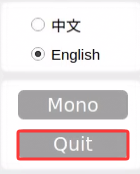
See the next section for an introduction to the interface and instructions for the buttons. Click the Quit button at the bottom right to close it.
After closing the LAB Tool, enter the command to restart the app auto-start service. Once startup is complete, the robotic arm returns to its initial position.
sudo systemctl restart start_app_node.service
Note
If the app auto-start service is not running, some app functions may not work properly. If the auto-start command has not been executed, restarting the robot will also automatically restart the app auto-start service.
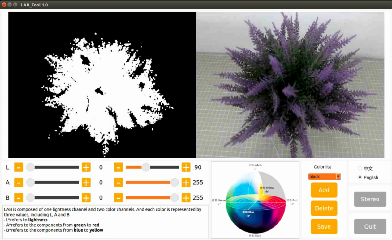
6.1.2 LAB TOOL Interface Introduction
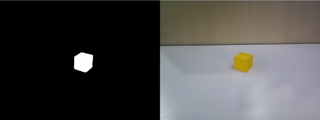
LABTOOL is divided into two parts, including the image display area and the recognition adjustment area.
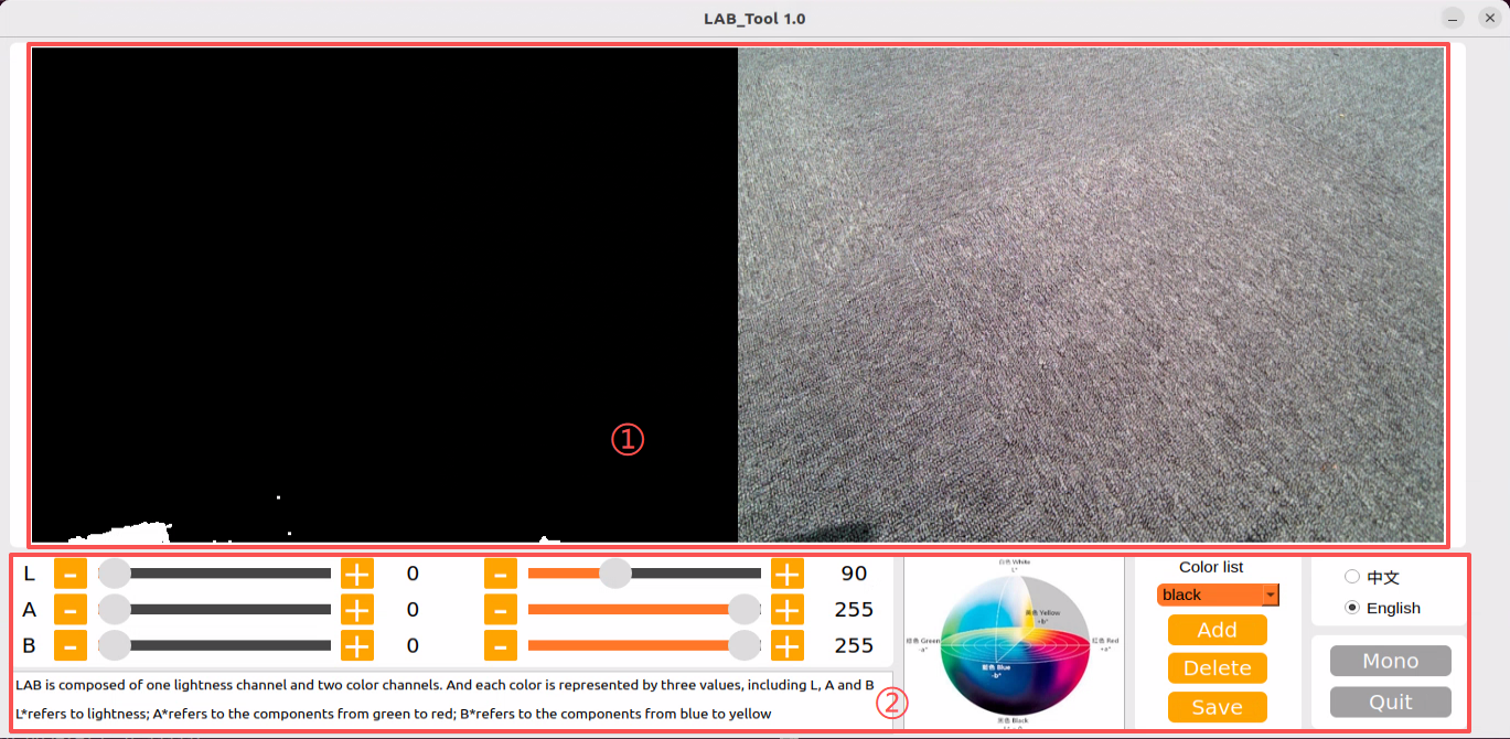
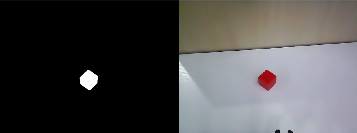
Image display area: The processed camera feed is shown on the left, and the raw feed is shown on the right.
Note
If the video feed fails to display, indicating a camera connection error, check the camera cable for a secure connection or reconnect it.
Adjustment Panel: Allows color-threshold tuning. The functions of each button are listed below.
| Icon | Function |
|---|---|
 |
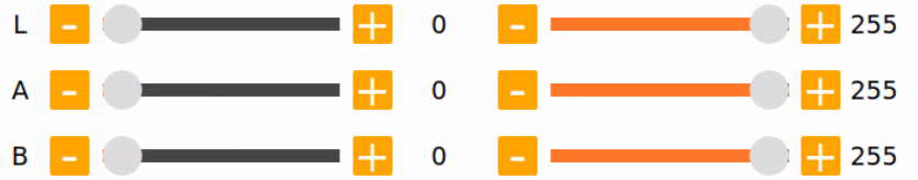
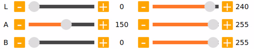
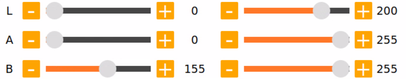
Sliders L, A, and B are respectively used to adjust L, A, and B components of the camera returned image. The left sliders set the min values for each channel, and the right sliders set the max values. |
 |
Select the target color for threshold tuning. |
 |
Delete the selected color. |
 |
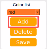
Add a new detectable color. |
 |
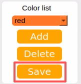
Save the adjusted value. |
 |
Switch the camera between the depth camera and the monocular camera. |
 |
Exit from the LAB TOOL. |
6.1.3 Adjust Color Threshold
Open LABTOOL, and select the color in the drop-down menu. Take adjusting the red color, for example.
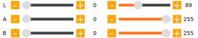
Modify all min values of L, A, and B to 0, and max values to 255.
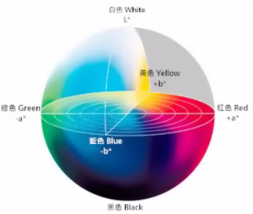
Put the red block within the camera frame. According to the LAB color space, adjust L, A, and B components to approach the zone of the target color.
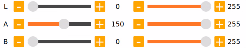
If the red area appears close to +a, increase the A component. Keep the A component’s max value unchanged and raise its min value until the target object in the left display turns white while all other areas turn black.
Based on the environment, modify the value of L and B. Increase the L component’s min value if the red tone is too light, or reduce its max value if it is too dark. Increase the B component’s min value if the red tone is too warm, or reduce its max value if it is too cool.
LAB Threshold Adjustment Parameter
| Color Component | Range | Corresponding Color Zone |
|---|---|---|
| L | 0~255 | Black-White(-L ~ +L) |
| A | 0~255 | Green-Red(-a ~ +a) |
| B | 0~255 | Blue-Yellow(-b ~ +b) |
Click Save to save the adjusted color threshold parameter.
6.1.4 Add New Color for Detection
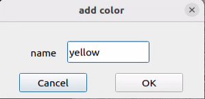
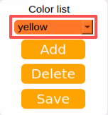
In addition to the built-in detectable colors, additional colors can be added. Yellow is used as an example below. The steps are as follows:
Open the LAB TOOL and click the Add button.
Then fill in yellow, and click OK.
Select the newly added color from the color list.
Face the camera at the yellow block. And drag the sliders of L, A, and B to adjust the color threshold till the object on the left turns white and the other area turns black.
Note
For instructions on adjusting color thresholds, refer to section 6.1.3 Adjust Color Threshold.
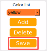
Click Save to save the adjusted color threshold parameter.
Once the adjustment is completed, press Ctrl + C to disable the camera service, then click Quit to exit the interface.
6.2 Color Recognition
This section demonstrates the detection of red, green, and blue objects using OpenCV, with the results displayed on the video feed. Before starting the feature, please prepare three objects in these colors: red, green, and blue.
6.2.1 Recognition Process
Firstly, the program will acquire the RGB image of the camera, scale the image, and perform Gaussian filtering on the image to convert the image color space from RGB to LAB.
Based on this, color thresholds are used to identify the color of the object within the circle. A mask is then applied to the image, which involves selecting parts of the image, graphics, or objects to globally or locally block out areas in the image for processing.
After masking, morphological operations, including opening and closing, are performed on the object image to refine the results.
Opening operation: Involves erosion followed by dilation. Effect: Removes small objects, smooths object boundaries, and does not affect object area. It can remove small particle noise and separate objects that are stuck together.
Erosion: Removes boundary pixels of an object, causing the edges to shrink inward. This operation can eliminate objects smaller than the structuring element.
Dilation: Expands the boundary pixels of an object by merging surrounding background pixels that are in contact with the object, causing the edges to grow outward.
Finally, the recognition results are overlaid on the return image.
6.2.2 Operation Steps
Note
Commands must be entered with correct capitalization. The Tab key can be used to auto-complete keywords.
Power on the robot and connect it via the NoMachine remote control software. For detailed information on connecting to a remote desktop, please refer to the section 1.7.2 AP Mode Connection Steps in the manual.
Click the terminal icon
 in the system desktop to open a command-line window.
Enter the command to disable the app auto-start service.
sudo systemctl stop start_app_node.service
Enter the command to start the camera node:
ros2 launch peripherals depth_camera.launch.py
Open a new terminal, navigate to the program directory, and start the color recognition feature by entering the following command:
cd ~/ros2_ws/src/example/example/color_detect && python3 color_detect_demo.py
The program will launch the camera image interface.
To exit the feature, press Ctrl + C in the terminal. If the program does not close successfully, try pressing Ctrl + C again.
6.2.3 Project Outcome
Note
After the feature starts, please ensure there is no other object containing the recognition color except the target object within the camera view. Otherwise, the recognition result will be affected.
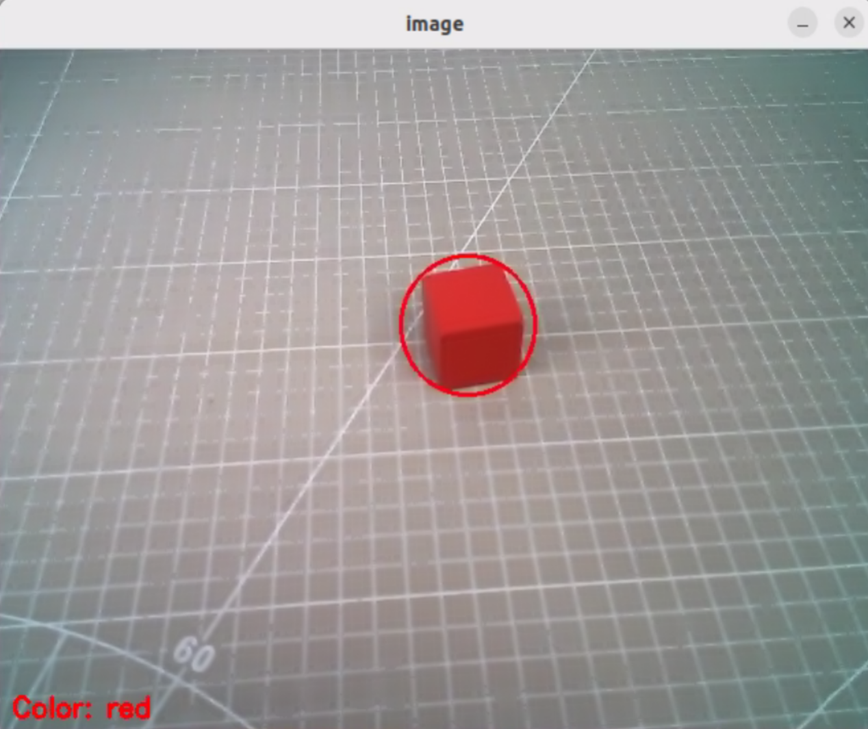
After the feature starts, put the objects within the camera’s view. When the target object is detected, the program will highlight it with a circle of the corresponding color and display the color name in the lower-left corner of the window. The program can detect objects in red, blue, and green.
6.2.4 Program Analysis
The feature’s source code is located at: /home/ubuntu/ros2_ws/src/example/example/color_detect/color_detect_demo.py
# Color detection

range_rgb = {
    'red': (0, 0, 255),
    'blue': (255, 0, 0),
    'green': (0, 255, 0),
    'black': (0, 0, 0),
    'white': (255, 255, 255),
}

def get_yaml_data(yaml_file):
    yaml_file = open(yaml_file, 'r', encoding='utf-8')
    file_data = yaml_file.read()
    yaml_file.close()

    data = yaml.load(file_data, Loader=yaml.FullLoader)

    return data

lab_data = get_yaml_data("/home/ubuntu/software/lab_tool/lab_config.yaml")
Main Function
Initializes the ROS node and creates the color detection node named color_detect_node, subscribes to the image topic /depth_cam/rgb/image_raw with image_callback as its callback function, runs the color detection main function using multi-threading, and waits for the node to shut down.
if __name__ == '__main__':
    rclpy.init()
    node = rclpy.create_node('color_detect_node')
    node.create_subscription(Image, '/depth_cam/rgb/image_raw', image_callback, 1)
    threading.Thread(target=main, daemon=True).start()
    rclpy.spin(node)
Functions
The camera callback function is primarily used to read the video stream from the topic and push it into a queue, ensuring real-time display.
def image_callback(ros_image):
    cv_image = bridge.imgmsg_to_cv2(ros_image, "bgr8")
    bgr_image = np.array(cv_image, dtype=np.uint8)
    if image_queue.full():
        # If the queue is full, discard the oldest image
        image_queue.get()
        # Put the image into the queue
    image_queue.put(bgr_image)
def main()
The images in the queue are read and passed into the run function to obtain the color-recognized frames, which are then displayed using cv2.
def main():
    running = True
    while running:
        try:
            image = image_queue.get(block=True, timeout=1)
        except queue.Empty:
            if not running:
                break
            else:
                continue
        image = run(image)
        cv2.imshow('image', image)
        key = cv2.waitKey(1)
        if key == ord('q') or key == 27:  # Press Q or Esc to exit
            break
YAML File Reading Function
def get_yaml_data(yaml_file):
    yaml_file = open(yaml_file, 'r', encoding='utf-8')
    file_data = yaml_file.read()
    yaml_file.close()

    data = yaml.load(file_data, Loader=yaml.FullLoader)

    return data
Maximum Contour Function
The function takes the contours detected by OpenCV as input, identifies the largest contour based on area, and returns both the contour and its area.
# Find the contour with the largest area
# The parameter is a list of contours to be compared
def getAreaMaxContour(contours):
    contour_area_temp = 0
    contour_area_max = 0
    area_max_contour = None

    for c in contours:  # Iterate through all contours
        contour_area_temp = math.fabs(cv2.contourArea(c))  # Calculate the area of the contour
        if contour_area_temp > contour_area_max:
            contour_area_max = contour_area_temp
            if contour_area_temp > 50:  # Only when the area is greater than 50, the contour with the largest area is valid. This allows to filter out interference)
                area_max_contour = c

    return area_max_contour, contour_area_max  # Return the contour with the largest area)
Color Recognition Function
The function takes an image as input and resizes it to the specified size (320, 240) to facilitate detection. The image is then processed with a Gaussian filter and converted to the LAB color space.
def run(img):
    global draw_color
    global color_list
    global detect_color

    img_copy = img.copy()
    img_h, img_w = img.shape[:2]

    frame_resize = cv2.resize(img_copy, size, interpolation=cv2.INTER_NEAREST)
    frame_gb = cv2.GaussianBlur(frame_resize, (3, 3), 3)
    frame_lab = cv2.cvtColor(frame_gb, cv2.COLOR_BGR2LAB)  # Convert image to LAB space

    max_area = 0
    color_area_max = None
    areaMaxContour_max = 0
    for i in ['red', 'green', 'blue']:
        frame_mask = cv2.inRange(frame_lab, tuple(lab_data['lab']['Stereo'][i]['min']), tuple(lab_data['lab']['Stereo'][i]['max']))  #Perform bitwise operation on the original image and the mask
        eroded = cv2.erode(frame_mask, cv2.getStructuringElement(cv2.MORPH_RECT, (3, 3)))  #Erode)
        dilated = cv2.dilate(eroded, cv2.getStructuringElement(cv2.MORPH_RECT, (3, 3))) #Dilate
        contours = cv2.findContours(dilated, cv2.RETR_EXTERNAL, cv2.CHAIN_APPROX_NONE)[-2]  #Find contours
        areaMaxContour, area_max = getAreaMaxContour(contours)  #Find the largest contour
        if areaMaxContour is not None:
            if area_max > max_area:#Find the maximum area
                max_area = area_max
                color_area_max = i
                areaMaxContour_max = areaMaxContour
The function loops through the predefined color list to perform color recognition and outputs the color corresponding to the largest detected contour.
    for i in ['red', 'green', 'blue']:
        frame_mask = cv2.inRange(frame_lab, tuple(lab_data['lab']['Stereo'][i]['min']), tuple(lab_data['lab']['Stereo'][i]['max']))  #Perform bitwise operation on the original image and the mask
        eroded = cv2.erode(frame_mask, cv2.getStructuringElement(cv2.MORPH_RECT, (3, 3)))  #Erode
        dilated = cv2.dilate(eroded, cv2.getStructuringElement(cv2.MORPH_RECT, (3, 3))) #Dilate
        contours = cv2.findContours(dilated, cv2.RETR_EXTERNAL, cv2.CHAIN_APPROX_NONE)[-2]  #Find contours
        areaMaxContour, area_max = getAreaMaxContour(contours)  #Find the largest contour
        if areaMaxContour is not None:
            if area_max > max_area:#Find the maximum area
                max_area = area_max
                color_area_max = i
                areaMaxContour_max = areaMaxContour
Only contours with an area greater than 200 are considered, smaller contours are filtered out. For contours larger than 200, the function calculates the contour coordinates and highlights the target color’s position in the frame based on the largest contour’s color.
    if max_area > 200:  # The maximum area is found
        ((centerX, centerY), radius) = cv2.minEnclosingCircle(areaMaxContour_max)  # Obtain the minimum circumscribed circle
        centerX = int(common.val_map(centerX, 0, size[0], 0, img_w))
        centerY = int(common.val_map(centerY, 0, size[1], 0, img_h))
        radius = int(common.val_map(radius, 0, size[0], 0, img_w))
        cv2.circle(img, (centerX, centerY), radius, range_rgb[color_area_max], 2)# Draw circle

        if color_area_max == 'red':  # Red has the maximum area
            color = 1
        elif color_area_max == 'green':  # Green has the maximum area
            color = 2
        elif color_area_max == 'blue':  # Blue has the maximum area
            color = 3
        else:
            color = 0
        color_list.append(color)

        if len(color_list) == 3:  # Determine multiple times
            # Averaging
            color = int(round(np.mean(np.array(color_list))))
            color_list = []
            if color == 1:
                detect_color = 'red'
                draw_color = range_rgb["red"]
            elif color == 2:
                detect_color = 'green'
                draw_color = range_rgb["green"]
            elif color == 3:
                detect_color = 'blue'
                draw_color = range_rgb["blue"]
            else:
                detect_color = 'None'
                draw_color = range_rgb["black"]
    else:
        detect_color = 'None'
        draw_color = range_rgb["black"]

    cv2.putText(img, "Color: " + detect_color, (10, img.shape[0] - 10), cv2.FONT_HERSHEY_SIMPLEX, 0.65, draw_color, 2)

    return img
6.3 QR Code Creation and Recognition
This section is divided into two parts. The first part explains how to create a QR code, and the second part focuses on recognizing the created QR code and decoding its information via the terminal.
6.3.1 QR Code Generation
Generation Process
First, create an instance of the QR code tool and set its detailed parameters.
Next, obtain the input data and populate it into the QR code.
Finally, generate a QR code image based on the data, display it in a window, and save it to the specified path.
Creation Steps
Note
Commands must be entered with correct capitalization. The Tab key can be used to auto-complete keywords.
Power on the robot and connect it via the NoMachine remote control software. For detailed information on connecting to a remote desktop, please refer to the section 1.7.2 AP Mode Connection Steps in the manual.
Click the terminal icon
in the system desktop to open a command-line window.Enter the command to disable the app auto-start service.
sudo systemctl stop start_app_node.service
Enter the following command to switch to the program directory and start the QR code creation program:
cd ~/ros2_ws/src/example/example/qrcode && python3 qrcode_creater.py
After launching the program, enter characters in the terminal to generate a QR code. For example, type ubuntu.

Press Enter, and a QR code containing the input data will be displayed.

To exit the QR code window, press the ESC key or the Q key.
Returning to the command-line terminal, the message displayed below confirms that the QR code has been successfully generated and saved.

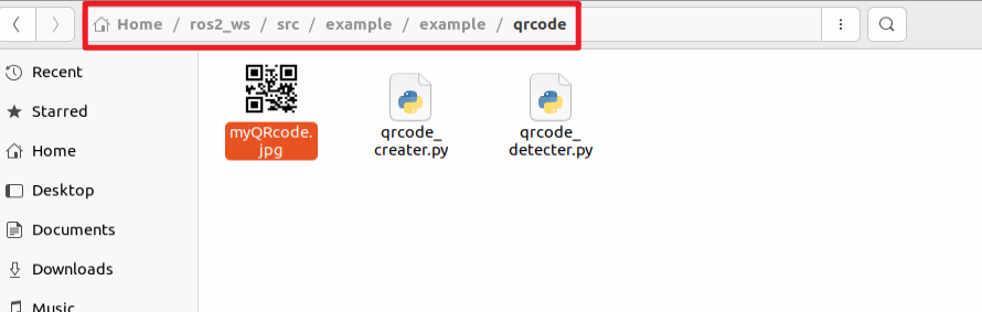
Next, click the taskbar on the left side of the system interface, then click
 to open the file manager. Navigate to the directory highlighted in the red box below to find that the generated QR code has been exported to the host system.
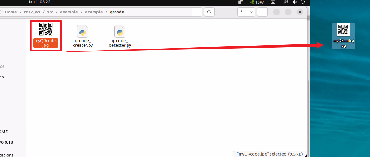
Drag the image to the PC desktop using NoMachine by dragging with the mouse. The image can then be printed or transferred to a photo album.
Program Analysis
The source code for the program is located at: /home/ubuntu/ros2_ws/src/example/example/qrcode/qrcode_creater.py
# encoding: utf-8
import os
import cv2
import qrcode
import numpy as np

def create_qrcode(data, file_name):
    '''
    version:An integer value between 1 and 40 that controls the size of the QR code. The minimum value is 1, which indicates a 12x12 matrix.
            To let the program determine the size automatically, set the value to None and use the fit parameter.
    error_correction:It controls the error correction capability of the QR code, and can take one of the following four constants.
      ERROR_CORRECT_L:Can correct about 7% or fewer errors.
      ERROR_CORRECT_M(default):Can correct about 15% or fewer errors.
      ROR_CORRECT_H:Can correct about 30% or fewer errors.
    box_size:Controls the number of pixels in each small square in the QR code
    border:Controls the number of squares in the border, the distance between the QR code and the image boundary. Default is 4, which is the minimum value specified by the relevant standard.
    '''
    qr = qrcode.QRCode(
        version=1,
        error_correction=qrcode.constants.ERROR_CORRECT_H,
        box_size=5,
        border=4)
    # Add data
    qr.add_data(data)
    # Fill data
    qr.make(fit=True)
    # Generate image
    img = qr.make_image(fill_color=(0, 0, 0), back_color=(255, 255, 255))
Creating a QR Code Tool Object
Use the qrcode module to create the required object and set the parameters for the QR code.
    qr = qrcode.QRCode(
        version=1,
        error_correction=qrcode.constants.ERROR_CORRECT_H,
        box_size=5,
        border=4)
    # Add data
    qr.add_data(data)
The parameters of the function shown above are as follows:
The first parameter, version, is an integer from 1 to 40 that controls the size of the QR code. To let the program determine the size automatically, set this parameter to None and use the fit parameter.
The second parameter, error_correction, controls the error correction level of the QR code and can take the following values:
ERROR_CORRECT_Lallows approximately 7% or less of errors to be corrected.ERROR_CORRECT_Mis the default value and allows approximately 15% or less of errors to be corrected.ROR_CORRECT_Hallows approximately 30% or less of errors to be corrected.
The third parameter, box_size, controls the number of pixels contained in each module of the QR code.
The fourth parameter, border, controls the number of modules included in the border and defines the distance between the QR code and the image edge. The default value is 4, which is the minimum required by the relevant standard.
Generating a QR Code
Data is added using the add_data and make functions, and the QR code image is generated using the make_image function.
    # Add data
    qr.add_data(data)
    # Fill data
    qr.make(fit=True)
    # Generate image
    img = qr.make_image(fill_color=(0, 0, 0), back_color=(255, 255, 255))
    opencv_img = cv2.cvtColor(np.asarray(img), cv2.COLOR_RGB2BGR)
The parameters of the make_image function are as follows:
fill_color=(0, 0, 0) sets the fill color of the QR code, which is black in this case.
back_color=(255, 255, 255) sets the background color of the QR code, which is white.
Displaying the Image
Convert the image’s color space using the cvtColor function, then display it in a window using the imshow function.
   while True:
        cv2.imshow('img', opencv_img)
        k = cv2.waitKey(1)
        if k != -1:
            break
    cv2.imwrite(file_name, opencv_img)
    print('save', data, file_name)
Saving the Image
Use the imwrite function to save the generated QR code image and print the relevant information.
    cv2.imwrite(file_name, opencv_img)
    print('save', data, file_name)
The parameters of the imwrite function are:
file_name specifies the storage path of the image.
opencv_img is the image to be saved.
6.3.2 QR Code Recognition
In the previous section, a QR code is created, which will be used to demonstrate recognizing the content of a QR code.
Recognition Process
First, create an instance of the QR code detector and load the required network structure and model weight files for detection.
Next, capture the video stream from the camera and perform detection on each frame.
Finally, when a QR code is detected, it will be highlighted with a bounding box, and the content of the QR code will be printed.
QR Code Recognition Steps
Note
Commands must be entered with correct capitalization. The Tab key can be used to auto-complete keywords.
Power on the robot and connect it via the NoMachine remote control software. For detailed information on connecting to remote desktop, please refer to section 1.7.2 AP Mode Connection Steps in the manual.
Click the terminal icon
in the system desktop to open a command-line window.Enter the command to disable the app auto-start service.
sudo systemctl stop start_app_node.service
Enter the command to start the camera node:
ros2 launch peripherals depth_camera.launch.py
Open a new ROS2 terminal, navigate to the program directory, and start the QR code recognition program by entering the following command:
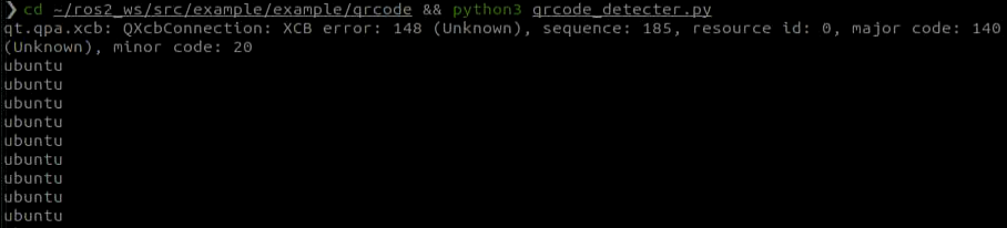
cd ~/ros2_ws/src/example/example/qrcode && python3 qrcode_detecter.py
To exit the feature, press Ctrl + C in the terminal. If the program does not close successfully, try pressing Ctrl + C again.
Project Outcome
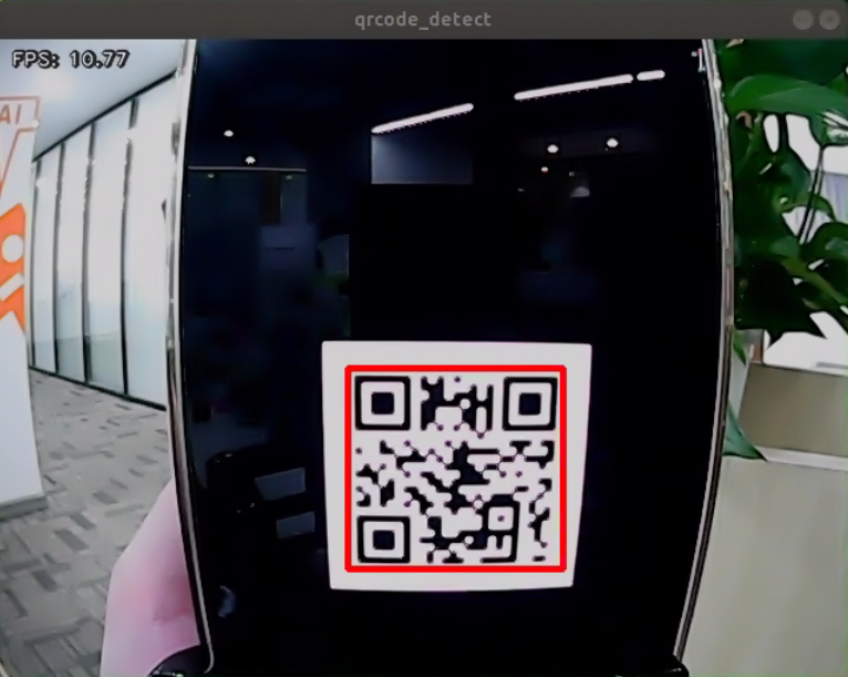
After starting the feature, the QR code appearing in the returned video frame is detected, highlighted with a red box, and its content is printed.
Program Analysis
The source code for the program is located at: /home/ubuntu/ros2_ws/src/example/example/qrcode/qrcode_detecter.py
#!/usr/bin/env python3
# encoding: utf-8
import os
import cv2
import queue
import rclpy
import threading
import numpy as np
from rclpy.node import Node
from cv_bridge import CvBridge
from sensor_msgs.msg import Image

class QRCodeDetectNode(Node):
    def __init__(self, name):
        rclpy.init()
        super().__init__(name)
        self.running = True
        self.bridge = CvBridge()
        self.model_path = os.path.join(os.path.abspath(os.path.split(os.path.realpath(__file__))[0]), 'model/detector.tflite')
        self.image_queue = queue.Queue(maxsize=2)
        self.image_sub = self.create_subscription(Image, '/depth_cam/rgb0/image_raw', self.image_callback, 1)
        self.qcd = cv2.QRCodeDetector()
        threading.Thread(target=self.main, daemon=True).start()

    def image_callback(self, ros_image):
        cv_image = self.bridge.imgmsg_to_cv2(ros_image, "bgr8")
        bgr_image = np.array(cv_image, dtype=np.uint8)
Main Function
Initialize the QRCodeDetectNode and set the node name to qrcode_detect.
Wait for the ROS node to shut down.
If the node shuts down, unregister the current node.
def main():
    node = QRCodeDetectNode('qrcode_detect')
    try:
        rclpy.spin(node)
    except KeyboardInterrupt:
        node.destroy_node()
        rclpy.shutdown()
        print('shutdown')
    finally:
        print('shutdown finish')

if __name__ == "__main__":
    main()
QRCodeDetectNodeClass
The class initializes the node, defines parameters, and starts the self.main function.
Parameters:
self.running determines whether detection is enabled.
self.model_path is the path to the detection model.
self.image_queue is the queue for storing images.
self.image_sub subscribes to the camera video stream.
self.qcd initializes the QR code detection model.
        super().__init__(name)
        self.running = True
        self.bridge = CvBridge()
        self.model_path = os.path.join(os.path.abspath(os.path.split(os.path.realpath(__file__))[0]), 'model/detector.tflite')
        self.image_queue = queue.Queue(maxsize=2)
        self.image_sub = self.create_subscription(Image, '/depth_cam/rgb0/image_raw', self.image_callback, 1)
        self.qcd = cv2.QRCodeDetector()
        threading.Thread(target=self.main, daemon=True).start()

    def image_callback(self, ros_image):
        cv_image = self.bridge.imgmsg_to_cv2(ros_image, "bgr8")
        bgr_image = np.array(cv_image, dtype=np.uint8)
        if self.image_queue.full():
            # If the queue is full, discard the oldest image
            self.image_queue.get()
            # Put the image into the queue
        self.image_queue.put(bgr_image)

    def main(self):
        while self.running:
            try:
                image = self.image_queue.get(block=True, timeout=1)
            except queue.Empty:
                if not self.running:
                    break
                else:
                    continue
            ret_qr, decoded_info, points, _ = self.qcd.detectAndDecodeMulti(image)
            if ret_qr:
                for s, p in zip(decoded_info, points):
                    if s:
                        print(s)
                        color = (0, 255, 0)
                    else:
                        color = (0, 0, 255)
                    image = cv2.polylines(image, [p.astype(int)], True, color, 8)
            cv2.imshow('image', image)
            key = cv2.waitKey(1)
            if key == ord('q') or key == 27:  # Press q or esc to exit
                break
Functions:
The camera callback function reads the camera video stream and places the frames into the queue self.image_queue, automatically updating and discarding outdated frames.
    def image_callback(self, ros_image):
        cv_image = self.bridge.imgmsg_to_cv2(ros_image, "bgr8")
        bgr_image = np.array(cv_image, dtype=np.uint8)
        if self.image_queue.full():
            # If the queue is full, discard the oldest image
            self.image_queue.get()
            # Put the image into the queue
        self.image_queue.put(bgr_image)
The main function handles QR code detection. It checks the self.running parameter to determine whether to start detection.
If True, it reads images from the self.image_queue, inputs them into the initialized detection model self.qcd, and finally prints the recognized content and draws the detection boxes based on the output.
    def main(self):
        while self.running:
            try:
                image = self.image_queue.get(block=True, timeout=1)
            except queue.Empty:
                if not self.running:
                    break
                else:
                    continue
            ret_qr, decoded_info, points, _ = self.qcd.detectAndDecodeMulti(image)
            if ret_qr:
                for s, p in zip(decoded_info, points):
                    if s:
                        print(s)
                        color = (0, 255, 0)
                    else:
                        color = (0, 0, 255)
                    image = cv2.polylines(image, [p.astype(int)], True, color, 8)
            cv2.imshow('image', image)
            key = cv2.waitKey(1)
            if key == ord('q') or key == 27:  # Press q or esc to exit
                break
6.4 Autonomous Line Following
6.4.1 Recognition Process
Firstly, the program will acquire the RGB image of the camera, scale the image, and perform Gaussian filtering on the image to convert the image color space from RGB to LAB.
Based on this, color thresholds are used to identify the color of the object within the circle. A mask is then applied to the image, which involves selecting parts of the image, graphics, or objects to globally or locally block out areas in the image for processing.
After masking, morphological operations, including opening and closing, are performed on the object image to refine the results.
Opening operation: Involves erosion followed by dilation. Effect: Removes small objects, smooths object boundaries, and does not affect object area. It can remove small particle noise and separate objects that are stuck together.
Erosion: Removes boundary pixels of an object, causing the edges to shrink inward. This operation can eliminate objects smaller than the structuring element.
Dilation: Expands the boundary pixels of an object by merging surrounding background pixels that are in contact with the object, causing the edges to grow outward.
Finally, the recognition results are overlaid on the return image.
6.4.2 Operation Steps
Note
Commands must be entered with correct capitalization. The Tab key can be used to auto-complete keywords.
Power on the robot and connect it via the NoMachine remote control software. For detailed information on connecting to a remote desktop, please refer to section 1.7.2 AP Mode Connection Steps in the manual.
Click the terminal icon
in the system desktop to open a command-line window.Enter the command to disable the app auto-start service.
sudo systemctl stop start_app_node.service
Enter the command to start the line-following node:
ros2 launch app line_following_node.launch.py debug:=true
Open a new terminal, navigate to the program directory, and start the autonomous line following feature by entering the following command:
ros2 service call /line_following/enter std_srvs/srv/Trigger {}
Next, in the current terminal, switch to the program directory and start the autonomous line following feature by entering the following command:
ros2 service call /line_following/set_running std_srvs/srv/SetBool "{data: True}"
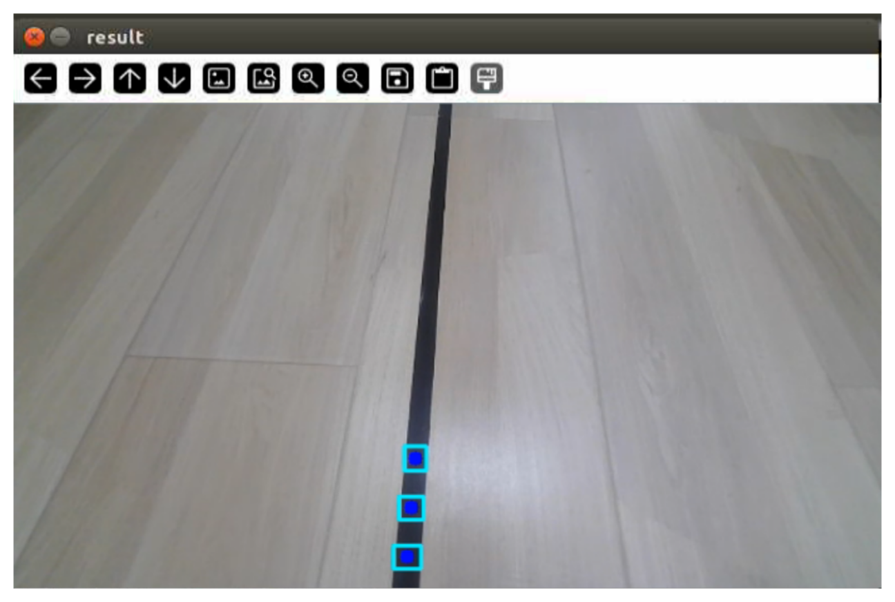
Click on the line in the interface, select the corresponding color of the track, and the robot will start following the line.
To stop this feature, return to the terminal and enter the following command:
ros2 service call /line_following/enter std_srvs/srv/Trigger {}
To exit the feature, press Ctrl + C in the terminal. If the program does not close successfully, try pressing Ctrl + C again.
6.4.3 Program Analysis
Launch Analysis
The program file corresponding to this section is located at /home/ubuntu/ros2_ws/src/app/launch/line_following_node.launch.py
Reading Paths
    compiled = os.environ['need_compile']
    debug = LaunchConfiguration('debug', default='false')
    debug_arg = DeclareLaunchArgument('debug', default_value=debug)
    if compiled == 'True':
        controller_package_path = get_package_share_directory('controller')
The package path is obtained using get_package_share_directory.
Launch
peripherals_package_path = '/home/ubuntu/ros2_ws/src/peripherals'
    line_following_node = GroupAction([
        IncludeLaunchDescription(
            PythonLaunchDescriptionSource(
                os.path.join(peripherals_package_path, 'launch/lidar.launch.py')),
            condition=IfCondition(debug),
            ),

        IncludeLaunchDescription(
            PythonLaunchDescriptionSource(
                os.path.join(peripherals_package_path, 'launch/depth_camera.launch.py')),
            condition=IfCondition(debug),
            ),

        IncludeLaunchDescription(
            PythonLaunchDescriptionSource(
                os.path.join(controller_package_path, 'launch/controller.launch.py')),
            condition=IfCondition(debug),
            ),

        Node(
            package='app',
            executable='line_following',
            output='screen',
            parameters=[{'debug': debug}],
            ),
controller_launch starts the motion control launch file.
depth_camera_launch starts the depth camera launch file.
lidar_launch starts the LiDAR launch file.
None
line_following_node starts the line following node.
            package='app',
            executable='line_following',
            output='screen',
Source Code Analysis
The source code for this demo is located at /home/ubuntu/ros2_ws/src/app/app/line_following.py
Note
Before modifying the program, backup the original factory code. Do not modify the source code file directly to avoid robot malfunction due to incorrect parameter changes.
Subscribe to the topic published by the camera node to obtain RGB images. Detect and select the line to be followed in the image, then sample its color to obtain the corresponding threshold range. Based on the line color information, extract the line features, calculate the offset of the robot relative to the line in the field of view, and drive the robot forward along the line while continuously correcting its position to keep the line centered in the image. LiDAR-based obstacle detection is also used to avoid obstacles.
The initialization function first defines several preset parameters, such as the color threshold ratio, stop threshold, and angle swing parameters. These parameters can affect the final recognition result. A color picker object is then defined for the color sampling step in this application, followed by the configuration of the additional LiDAR obstacle avoidance function. Next is the implementation of the LineFollower class, which mainly includes the image preprocessing function and the line-following logic.
Functions
Main:
def main():
    node = LineFollowingNode('line_following')
    rclpy.spin(node)
    node.destroy_node()
    rclpy.shutdown()
Starts the line-following node.
Class:
LineFollower:
class LineFollower:
    def __init__(self, color, node):
        self.node = node
Init:
    def __init__(self, color, node):
        self.node = node
        self.target_lab, self.target_rgb = color
        if 'Mecanum' in os.environ['MACHINE_TYPE'] or 'Acker' in os.environ['MACHINE_TYPE']:
            self.rois = ((0.90, 0.92, 0, 1, 0.7), (0.78, 0.80, 0, 1, 0.2), (0.66, 0.68, 0, 1, 0.1))
        else:
            self.rois = ((0.81, 0.83, 0, 1, 0.7), (0.69, 0.71, 0, 1, 0.2), (0.57, 0.59, 0, 1, 0.1))
        self.weight_sum = 1.0
Sets the line-following color and ROI list.
get_area_max_contour:
    def get_area_max_contour(contours, threshold=100):
        '''
        Get the contour of the largest area
        :param contours:
        :param threshold:
        :return:
        '''
        contour_area = zip(contours, tuple(map(lambda c: math.fabs(cv2.contourArea(c)), contours)))
        contour_area = tuple(filter(lambda c_a: c_a[1] > threshold, contour_area))
        if len(contour_area) > 0:
            max_c_a = max(contour_area, key=lambda c_a: c_a[1])
            return max_c_a
        return None
Gets the contour with the largest area.
Call:
    def __call__(self, image, result_image, threshold, color=None, use_color_picker=True):
        centroid_sum = 0
        h, w = image.shape[:2]

        if use_color_picker:
            min_color = [int(self.target_lab[0] - 50 * threshold * 2),
                         int(self.target_lab[1] - 50 * threshold),
                         int(self.target_lab[2] - 50 * threshold)]
            max_color = [int(self.target_lab[0] + 50 * threshold * 2),
                         int(self.target_lab[1] + 50 * threshold),
                         int(self.target_lab[2] + 50 * threshold)]
            target_color = self.target_lab, min_color, max_color
            lowerb = tuple(target_color[1])
            upperb = tuple(target_color[2])
        else:
            lowerb = tuple(color['min'])
            upperb = tuple(color['max'])
        for roi in self.rois:
            blob = image[int(roi[0]*h):int(roi[1]*h), int(roi[2]*w):int(roi[3]*w)]  # Intercept roi
            img_lab = cv2.cvtColor(blob, cv2.COLOR_RGB2LAB)  # Convert rgb into lab
            img_blur = cv2.GaussianBlur(img_lab, (3, 3), 3)  # Perform Gaussian filtering to reduce noise
            mask = cv2.inRange(img_blur, lowerb, upperb)  # Image binarization
            eroded = cv2.erode(mask, cv2.getStructuringElement(cv2.MORPH_RECT, (3, 3)))  # Corrode
            dilated = cv2.dilate(eroded, cv2.getStructuringElement(cv2.MORPH_RECT, (3, 3)))  # Dilate
            # cv2.imshow('section:{}:{}'.format(roi[0], roi[1]), cv2.cvtColor(dilated, cv2.COLOR_GRAY2BGR))
            contours = cv2.findContours(dilated, cv2.RETR_EXTERNAL, cv2.CHAIN_APPROX_TC89_L1)[-2]  # Find the contour
            max_contour_area = self.get_area_max_contour(contours, 30)  # Get the contour corresponding to the largest contour
            if max_contour_area is not None:
                rect = cv2.minAreaRect(max_contour_area[0])  # Minimum circumscribed rectangle
                box = np.intp(cv2.boxPoints(rect))  # Four corners
                for j in range(4):
                    box[j, 1] = box[j, 1] + int(roi[0]*h)
                cv2.drawContours(result_image, [box], -1, (0, 255, 255), 2)  # Draw the rectangle composed of four points
Performs color recognition based on the set color and provides feedback on the recognized image and angle.
LineFollowingNode:
class LineFollowingNode(Node):
    def __init__(self, name):
        rclpy.init()
        super().__init__(name, allow_undeclared_parameters=True, automatically_declare_parameters_from_overrides=True)

        self.name = name
        self.color = ''
        self.set_above = False
        self.set_callback = False
        self.is_running = False
Init:
    def __init__(self, name):
        rclpy.init()
        super().__init__(name, allow_undeclared_parameters=True, automatically_declare_parameters_from_overrides=True)

        self.name = name
        self.color = ''
        self.set_above = False
        self.set_callback = False
        self.is_running = False
        self.color_picker = None
        self.follower = None
        self.scan_angle = math.radians(45)
        self.pid = pid.PID(0.01, 0.0, 0.0)
        self.empty = 0
        self.count = 0
        self.stop = False
        self.threshold = 0.5
Initializes parameters required for the program, calls the chassis and camera nodes, and starts services such as enter, exit, start, set color, get color, and set threshold.
get_node_state:
    def get_node_state(self, request, response):
        response.success = True
        return response
Sets the current node state.
Main:
    def main(self):
        while True:
            try:
                image = self.image_queue.get(block=True, timeout=1)
            except queue.Empty:
                continue

            result = cv2.cvtColor(image, cv2.COLOR_RGB2BGR)
            # cv2.imshow("image", result)
            cv2.imshow("image", cv2.resize(result, (display_size[0], display_size[1])))
            if self.debug and not self.set_callback:
                self.set_callback = True
                # Set callback function for mouse clicking event
                cv2.setMouseCallback("image", self.mouse_callback)
            k = cv2.waitKey(1)
            if k != -1:
                break
Reads the image and uses the mouse for color selection.
mouse_callback:
    def mouse_callback(self, event, x, y, flags, param):
        if event == cv2.EVENT_LBUTTONDOWN:
            self.get_logger().info("x:{} y{}".format(x, y))
            msg = SetPoint.Request()
            if self.image_height is not None and self.image_width is not None:
                msg.data.x = x / self.image_width
                msg.data.y = y / self.image_height
                self.set_target_color_srv_callback(msg, SetPoint.Response())
Mouse color selection callback function to obtain the pixel coordinates of the current mouse position.
enter_srv_callback:
    def enter_srv_callback(self, request, response):
        self.get_logger().info('\033[1;32m%s\033[0m' % "line following enter")
        with self.lock:
            self.color = ''
            self.stop = False
            self.is_running = False
            self.color_picker = None
            self.pid = pid.PID(1.1, 0.0, 0.0)
            self.follower = None
            self.threshold = 0.5
            self.empty = 0
            if self.image_sub is None:
                if 'ROSOrin Pro' in self.machine_type:
                    self.camera_type = 'Stereo'
                    self.image_sub = self.create_subscription(Image, '/depth_cam/rgb0/image_raw', self.image_callback, 1)  # Subscribe to the camera
                else:
                    self.camera_type = 'Mono'
                    self.image_sub = self.create_subscription(Image, '/usb_cam/image_raw', self.image_callback, 1)  # Subscribe to the camera
            if self.lidar_sub is None:
                qos = QoSProfile(depth=1, reliability=QoSReliabilityPolicy.BEST_EFFORT)
                self.lidar_sub = self.create_subscription(LaserScan, '/scan_raw', self.lidar_callback, qos)  # Subscribe to LiDAR data
Starts autonomous line following, initializes robot motion parameters, and subscribes to camera and LiDAR topics.
exit_srv_callback:
    def exit_srv_callback(self, request, response):
        self.get_logger().info('\033[1;32m%s\033[0m' % "line following exit")
        try:
            if self.image_sub is not None:
                self.destroy_subscription(self.image_sub)
                self.image_sub = None
            if self.lidar_sub is not None:
                self.destroy_subscription(self.lidar_sub)
                self.lidar_sub = None
        except Exception as e:
            self.get_logger().error(str(e))
        with self.lock:
            self.is_running = False
            self.color_picker = None
            self.pid = pid.PID(0.01, 0.0, 0.0)
            self.follower = None
            self.threshold = 0.5
            self.mecanum_pub.publish(Twist())
        response.success = True
        response.message = "exit"
        return response
Exits the autonomous line following service, shuts down all active subscriptions, resets the PID controller, and stops line following.
set_target_color_srv_callback:
    def set_target_color_srv_callback(self, request, response):
        self.get_logger().info('\033[1;32m%s\033[0m' % "set_target_color")
        with self.lock:
            self.use_color_picker = True
            x, y = request.data.x, request.data.y
            self.get_logger().info(f'{request.data.x},{request.data.y}')
            # request.data.x  = request.data.x
            # request.data.y =
            self.follower = None
            if x == -1 and y == -1:
                self.color_picker = None
            else:
                self.color_picker = ColorPicker(request.data, 5)
                self.mecanum_pub.publish(Twist())
        response.success = True
        response.message = "set_target_color"
        return response
Service to set the target line-following color.
get_target_color_srv_callback:
    def get_target_color_srv_callback(self, request, response):
        self.get_logger().info('\033[1;32m%s\033[0m' % "get_target_color")
        response.success = False
        response.message = "get_target_color"
        with self.lock:
            if self.follower is not None:
                response.success = True
                rgb = self.follower.target_rgb
                response.message = "{},{},{}".format(int(rgb[0]), int(rgb[1]), int(rgb[2]))
        return response
Service to get the target line-following color.
set_running_srv_callback:
    def set_running_srv_callback(self, request, response):
        self.get_logger().info('\033[1;32m%s\033[0m' % "set_running")
        with self.lock:
            self.is_running = request.data
            self.empty = 0
            if not self.is_running:
                self.mecanum_pub.publish(Twist())
        response.success = True
        response.message = "set_running"
        return response
Service to start the autonomous line following feature.
set_threshold_srv_callback:
    def set_threshold_srv_callback(self, request, response):
        self.get_logger().info('\033[1;32m%s\033[0m' % "set threshold")
        with self.lock:
            self.threshold = request.data
            response.success = True
            response.message = "set_threshold"
            return response
Service to set the color threshold.
lidar_callback:
    def lidar_callback(self, lidar_data):
        # Data size= scanning angle/ the increased angle per scan
        if self.lidar_type != 'G4':
            min_index = int(math.radians(MAX_SCAN_ANGLE / 2.0) / lidar_data.angle_increment)
            max_index = int(math.radians(MAX_SCAN_ANGLE / 2.0) / lidar_data.angle_increment)
            left_ranges = lidar_data.ranges[:max_index]  # Left data
            right_ranges = lidar_data.ranges[::-1][:max_index]  # Right data
        elif self.lidar_type == 'G4':
            min_index = int(math.radians((360 - MAX_SCAN_ANGLE) / 2.0) / lidar_data.angle_increment)
            max_index = int(math.radians(180) / lidar_data.angle_increment)
            left_ranges = lidar_data.ranges[min_index:max_index][::-1]  # The left data
            right_ranges = lidar_data.ranges[::-1][min_index:max_index][::-1]  # The right data

        # Get data according to settings
        angle = self.scan_angle / 2
        angle_index = int(angle / lidar_data.angle_increment + 0.50)
        left_range, right_range = np.array(left_ranges[:angle_index]), np.array(right_ranges[:angle_index])

        left_nonzero = left_range.nonzero()
        right_nonzero = right_range.nonzero()
        left_nonan = np.isfinite(left_range[left_nonzero])
        right_nonan = np.isfinite(right_range[right_nonzero])
        # Take the nearest distance left and right
        min_dist_left_ = left_range[left_nonzero][left_nonan]
        min_dist_right_ = right_range[right_nonzero][right_nonan]
        if len(min_dist_left_) > 0 and len(min_dist_right_) > 0:
            min_dist_left = min_dist_left_.min()
            min_dist_right = min_dist_right_.min()
            if min_dist_left < self.stop_threshold or min_dist_right < self.stop_threshold:
                self.stop = True
            else:
                self.count += 1
                if self.count > 5:
                    self.count = 0
                    self.stop = False
The LiDAR callback function processes the received data and determines whether to stop moving.
image_callback:
    def image_callback(self, ros_image):
        cv_image = self.bridge.imgmsg_to_cv2(ros_image, "rgb8")
        rgb_image = np.array(cv_image, dtype=np.uint8)
        rgb_image = cv2.resize(rgb_image, (640,480))
        self.image_height, self.image_width = rgb_image.shape[:2]
        result_image = np.copy(rgb_image)  # The image used to display the result
        with self.lock:
            if self.use_color_picker:
                # Color picker and line recognition are exclusive. If there is color picker, start picking
                if self.color_picker is not None:  # Color picker exists
                    try:
                        target_color, result_image = self.color_picker(rgb_image, result_image)
                        if target_color is not None:
                            self.color_picker = None
                            self.follower = LineFollower(target_color, self)
                            self.get_logger().info("target color: {}".format(target_color))
                    except Exception as e:
                        self.get_logger().error(str(e))
                else:
                    twist = Twist()
                    twist.linear.x = 0.15
                    if self.follower is not None:
                        try:
                            result_image, deflection_angle = self.follower(rgb_image, result_image, self.threshold)
                            if deflection_angle is not None and self.is_running and not self.stop:
                                self.pid.update(deflection_angle)
                                if 'Acker' in self.machine_type:
                                    steering_angle = common.set_range(-self.pid.output, -math.radians(322/2000*180), math.radians(322/2000*180))
                                    if steering_angle != 0:
                                        R = 0.17706/math.tan(steering_angle)
                                        twist.angular.z = twist.linear.x/R
                                else:
                                    twist.angular.z = common.set_range(-self.pid.output, -1.0, 1.0)
                                self.mecanum_pub.publish(twist)
                            elif self.stop:
                                self.mecanum_pub.publish(Twist())
                            else:
                                self.pid.clear()
                        except Exception as e:
                            self.get_logger().error(str(e))
            else:
                twist = Twist()
                if self.color in common.range_rgb:
                    twist.linear.x = 0.15
                    self.follower = LineFollower([None, common.range_rgb[self.color]], self)
                    result_image, deflection_angle = self.follower(rgb_image, result_image, self.threshold, self.lab_data['lab'][self.camera_type][self.color], False)
                    if deflection_angle is not None and self.is_running and not self.stop:
                        self.pid.update(deflection_angle)
                        if 'Acker' in self.machine_type:
                            steering_angle = common.set_range(-self.pid.output, -math.radians(322/2000*180), math.radians(322/2000*180))
                            if steering_angle != 0:
                                R = 0.17706/math.tan(steering_angle)
                                twist.angular.z = twist.linear.x/R
                        else:
                            twist.angular.z = common.set_range(-self.pid.output, -1.0, 1.0)
                        self.mecanum_pub.publish(twist)
                    elif self.stop:
                        self.mecanum_pub.publish(Twist())
                    else:
                        self.pid.clear()
                else:
                    self.mecanum_pub.publish(twist)
        if self.debug:
            if self.image_queue.full():
                # If the queue is full, discard the oldest image
                self.image_queue.get()
The camera callback function uses the received data to invoke the color picker and controls the robot’s movement along the recognized line using PID.
6.5 AR Vision
6.5.1 Overview
First, topic messages published by the camera node are subscribed to obtain RGB images, which are then converted to grayscale and resized.
Next, a service call is used to set the 3D model to be displayed.
Finally, when the camera detects an AprilTag marker, the corresponding 3D model is overlaid at the marker position.
6.5.2 Operation Steps
Note
Commands must be entered with correct capitalization. The Tab key can be used to auto-complete keywords.
Power on the robot and connect it to the remote control software NoMachine. For instructions on connecting to the remote desktop, refer to 1.7.2 AP Mode Connection Steps.
Click the terminal icon
on the desktop to open a terminal.Run the following command to stop the auto-start service.
sudo systemctl stop start_app_node.service
Run the following command to start the AR vision feature.
ros2 launch example ar_detect.launch.py
Run the following command to set the AR model.
ros2 service call /ar_detect/set_model interfaces/srv/SetString "{data: 'bicycle'}"
Available models:
bicycle: bicyclefox: foxchair: chaircow: cowwolf: wolfrectangle: simple cube frame
To stop the feature, press Ctrl + C in the terminal. If the program does not close successfully, try pressing Ctrl + C again.
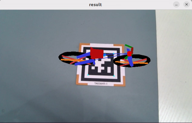
6.5.3 Project Outcome
After the feature starts, place the tag card within the camera field of view. When the tag is detected, coordinate axes are drawn at the tag position, the four corners of the tag are marked with blue dots, and the tag ID is displayed.
6.5.4 Program Analysis
Launch File Analysis
The source code is located at:
/home/ubuntu/ros2_ws/src/example/example/ar_detect/ar_detect.launch.py
It defines the content to be launched, gets the paths of the peripherals and example packages, stand arts the depth_camera_launch file. Creates the ROS2 node
ar_detect, defines the executable file, and finally returns the launch item list.
def launch_setup(context):
    compiled = os.environ['need_compile']
    debug = LaunchConfiguration('debug', default='true')
    debug_arg = DeclareLaunchArgument('debug', default_value=debug)
    if compiled == 'True':
        peripherals_package_path = get_package_share_directory('peripherals')
        example_package_path = get_package_share_directory('example')
    else:
        peripherals_package_path = '/home/ubuntu/ros2_ws/src/peripherals'
        example_package_path = '/home/ubuntu/ros2_ws/src/example'

    depth_camera_launch = IncludeLaunchDescription(
        PythonLaunchDescriptionSource(
            os.path.join(peripherals_package_path, 'launch/depth_camera.launch.py')),
    )


    ar_detect_node = Node(
        package='example',
        executable='ar_detect',
        output='screen',
        parameters=[{'debug': debug}],
    )

    return [
            debug_arg,
            depth_camera_launch,
            ar_detect_node,
            ]
This is the entry function of the
ROS2 Launchfile. It defines the content to be launched.
def generate_launch_description():
    return LaunchDescription([
        OpaqueFunction(function = launch_setup)
    ])
It creates
LaunchServiceand passes the launch content to it for execution.
if __name__ == '__main__':
    # Create a LaunchDescription object
    ld = generate_launch_description()

    ls = LaunchService()
    ls.include_launch_description(ld)
    ls.run()
Python Source Code Analysis
The source code is located at:
/home/ubuntu/ros2_ws/src/example/example/ar_detect/ar_detect.py
It gets the default storage path of the model.
MODEL_PATH = os.path.join(os.path.abspath(os.path.join(os.path.split(os.path.realpath(__file__))[0])), 'ar_models')
The
draw_rectanglefunction is used to draw a cube. The parameterimgis the image used to draw the cube. The parameterimgptsis the corner point set of the cube. The function returns the image containing the cube.
def draw_rectangle(img, imgpts):
    '''
    Draw the cube
    :param img: The image to draw the cube
    :param imgpts: Angular point of the cube
    :return: The image to draw the cube
    '''
    imgpts = np.int32(imgpts).reshape(-1, 2)
    cv2.drawContours(img, [imgpts[:4]], -1, (0, 255, 0), -3)  # Draw contour points, filled.
    for i, j in zip(range(4), range(4, 8)):
        cv2.line(img, tuple(imgpts[i]), tuple(imgpts[j]), (255), 3)  # Draw points connected by lines.
    cv2.drawContours(img, [imgpts[4:]], -1, (0, 0, 255), 3)  # Draw contour points, unfilled.

    return img
OBJPis a set of world-coordinate points solved with NumPy. It contains the four corner points of the AprilTag marker, left-bottom, right-bottom, left-top, and right-top, plus the center point, and is used to calculate the camera extrinsic parameters.AXISdefines the coordinates of the eight vertices of the cube. It is used to draw the cube frame when the marker is detected, with four points on the bottom face, four points on the top face, and a height of 2.MODELS_SCALEis a dictionary of scaling ratios for each 3D model. It is used to resize theOBJPmodel to a suitable display size, such as 50 for the bicycle, 400 for the chair, and 0.4 for the cow.
OBJP = np.array([[-1, -1,  0],
                 [ 1, -1,  0],
                 [-1,  1,  0],
                 [ 1,  1,  0],
                 [ 0,  0,  0]], dtype=np.float32)

# Draw the coordinate of the cube
AXIS = np.float32([[-1, -1, 0],
                   [-1,  1, 0],
                   [ 1,  1, 0],
                   [ 1, -1, 0],
                   [-1, -1, 2],
                   [-1,  1, 2],
                   [ 1,  1, 2],
                   [ 1, -1, 2]])

# Model scaling
MODELS_SCALE = {
                'bicycle': 50,
                'fox': 4,
                'chair': 400,
                'cow': 0.4,
                'wolf': 0.6,
                }
def __init__(self, name)Method
It initializes the ROS2 node and allows undeclared parameters and automatically declared override parameters.
        super().__init__(name, allow_undeclared_parameters=True, automatically_declare_parameters_from_overrides=True)
        self.name = name
It initializes the camera intrinsic matrix, including focal length and principal point coordinates, and sets the distortion coefficient array used for image correction.
        self.camera_intrinsic = np.matrix([[619.063979, 0,          302.560920],
                                           [0,          613.745352, 237.714934],
                                           [0,          0,          1]])
        self.dist_coeffs = np.array([0.103085, -0.175586, -0.001190, -0.007046, 0.000000])
It initializes variables such as the model object, subscribers, and target model, creates CvBridge for ROS image and OpenCV format conversion, and gets the machine type and camera type from environment variables. Instantiates the AprilTag detector using the tag36h11 family, and creates a thread lock to ensure thread safety.
        self.obj = None
        self.image_sub = None
        self.target_model = None
        self.camera_info_sub = None
        self.bridge = CvBridge()
        self.machine = os.environ['MACHINE_TYPE']
        self.camera = os.environ['DEPTH_CAMERA_TYPE']
        self.tag_detector = apriltag("tag36h11")  # Instantiate apriltag
        self.lock = threading.RLock()  # Thread lock
Create an image publisher to publish the processed result image to the ~/image_result topic. Create the following services: ~/enter to enter AR detection mode, ~/exit to exit AR detection mode, ~/set_model to set the 3D model to display, and ~/init_finish to get the node status. Create a heartbeat mechanism with a 5-second interval for automatic exit on timeout. Read the value of the debug parameter.
        self.result_publisher = self.create_publisher(Image, '~/image_result', 1)  # Publish the final image
        self.create_service(Trigger, '~/enter', self.enter_srv_callback)  # Enter the feature service
        self.create_service(Trigger, '~/exit', self.exit_srv_callback)  # Exit the feature service
        Heart(self, self.name + '/heartbeat', 5, lambda _: self.exit_srv_callback(request=Trigger.Request(), response=Trigger.Response()))  # Heartbeat package
        self.create_service(SetString, '~/set_model', self.set_model_srv_callback)  # Set the model service
        self.debug = self.get_parameter('debug').value
        self.create_service(Trigger, '~/init_finish', self.get_node_state)
If debug mode is enabled, the enter service is automatically called to start AR detection.
        if self.debug:
            self.enter_srv_callback(Trigger.Request(), Trigger.Response())
def get_node_state(self, request, response)
This is the callback method of the ~/init_finish service. It returns success = True, indicating that the node has been initialized and can be used by external systems to confirm whether the ar_detect node is ready.
    def get_node_state(self, request, response):
        response.success = True
        return response
def enter_srv_callback(self, request, response)
It responds to the ~/enter service call, starts the AR vision feature, uses a thread lock to ensure thread safety, and resets the model object and target model to None.
    def enter_srv_callback(self, request, response):
        # Enter the service
        self.get_logger().info('\033[1;32m%s\033[0m' % "ar enter")
        # If there is a node when entering the service, cancel subscription and subscribe again.

        with self.lock:
            self.obj = None
            self.target_model = None
            if self.image_sub is None:
                self.image_sub = self.create_subscription(Image, '/depth_cam/rgb0/image_raw', self.image_callback, 1)  # Subscribe to the camera

            if self.camera_info_sub is None:
                self.camera_info_sub = self.create_subscription(CameraInfo, '/depth_cam/rgb0/camera_info', self.camera_info_callback, 1) # Subscribe to the camera information

        response.success = True
        response.message = "enter"
        return response
def exit_srv_callback(self, request, response)
It responds to the ~/exit service call, stops the AR vision feature, unsubscribes to save resources, and destroys the image subscription self.image_sub to stop receiving RGB images. Destroys the camera information subscription self.camera_info_sub to stop receiving camera intrinsics, sets the subscription objects to None, and uses exception handling to ensure safe unsubscription. Logs an error if an exception occurs, and returns a successful response with the message exit.
	def exit_srv_callback(self, request, response):
        # Exit the service
        self.get_logger().info('\033[1;32m%s\033[0m' % "ar exit")
        # Cancel the subscribtion when exiting the service to save the expenditure.
        try:
            if self.image_sub is not None:
                self.destroy_subscription(self.image_sub)
                self.image_sub = None
            if self.camera_info_sub is not None:
                self.destroy_subscription(self.camera_info_sub)
                self.camera_info_sub = None
        except Exception as e:
            self.get_logger().error(str(e))
        response.success = True
        response.message = "exit"
        return response
def set_model_srv_callback(self, request, response)
It responds to the ~/set_model service call and sets the 3D model to be displayed.
With the thread lock enabled to ensure thread safety, if the request data is an empty string, the target model is cleared. Otherwise, the target model name is set.
        with self.lock:
            self.get_logger().info('\033[1;32m%s\033[0m' % "set model {}".format(request.data))
            if request.data == "":
                self.target_model = None
            else:
                self.target_model = request.data
Model loading and preprocessing:
If the model is not rectangle, load the corresponding OBJ file from the ar_models directory and reverse the face order to ensure correct rendering. Traverse all faces of the model to extract the vertex coordinates of each face from the first three values and the color information from the last three values, except for the cow and wolf models. Scale the vertices according to the MODELS_SCALE dictionary. Apply position and rotation adjustments based on the model type. For bicycle, apply a translation and rotate 180 degrees around the Z-axis. For fox and chair, rotate -90 degrees around the Z-axis. All other models remain unchanged. Convert the color values to the 0 to 255 range. For the cow and wolf models, the color value is None and will be assigned manually later. Store all processed face data in self.obj.
                if self.target_model != 'rectangle':  # If the cube is not being drawn.
                    # Load the model
                    obj = obj_load(os.path.join(MODEL_PATH, self.target_model + '.obj'), swapyz=True)
                    obj.faces = obj.faces[::-1]
                    new_faces = []
                    # Analyze the model and get the point coordinates.
                    for face in obj.faces:
                        face_vertices = face[0]
                        points = []
                        colors = []
                        for vertex in face_vertices:
                            data = obj.vertices[vertex - 1]
                            points.append(data[:3])
                            if self.target_model != 'cow' and self.target_model != 'wolf':
                                colors.append(data[3:])
                        scale_matrix = np.array([[1, 0, 0], [0, 1, 0], [0, 0, 1]]) * MODELS_SCALE[self.target_model]  # Scale
                        points = np.dot(np.array(points), scale_matrix)
                        if self.target_model == 'bicycle':
                            points = np.array([[p[0] - 670, p[1] - 350, p[2]] for p in points])
                            points = R.from_euler('xyz', (0, 0, 180), degrees=True).apply(points)
                        elif self.target_model == 'fox':
                            points = np.array([[p[0], p[1], p[2]] for p in points])
                            points = R.from_euler('xyz', (0, 0, -90), degrees=True).apply(points)
                        elif self.target_model == 'chair':
                            points = np.array([[p[0], p[1], p[2]] for p in points])
                            points = R.from_euler('xyz', (0, 0, -90), degrees=True).apply(points)
                        else:
                            points = np.array([[p[0], p[1], p[2]] for p in points])
                        if len(colors) > 0:
                            color = tuple(255 * np.array(colors[0]))
                        else:
                            color = None
                        new_faces.append((points, color))
                    self.obj = new_faces
It returns a successful response with the message set_model.
        response.success = True
        response.message = "set_model"
        return response
def camera_info_callback(self, msg)
This is the callback method for the /depth_cam/rgb0/camera_info topic. It uses a thread lock to ensure thread safety, updates the camera intrinsic parameters, converts the intrinsic matrix msg.k into a 3×3 array, and stores it in self.camera_intrinsic. It converts the distortion coefficient array msg.d and stores it in self.dist_coeffs.
    def camera_info_callback(self, msg):
        # Camera internal parameter callback
        with self.lock:
            self.camera_intrinsic = np.array(msg.k).reshape(3, -1)
            self.dist_coeffs = np.array(msg.d)
def image_callback(self, ros_image)
This is the callback method for the /depth_cam/rgb0/image_raw topic.
Image format conversion:
        cv_image = self.bridge.imgmsg_to_cv2(ros_image, "rgb8")
        rgb_image = np.array(cv_image, dtype=np.uint8)
        result_image = np.copy(rgb_image)
Image processing: A thread lock is used to ensure thread safety. The image_proc function is called for AR vision processing, including AprilTag detection, pose estimation, and model overlay. Exception handling is used to log errors without affecting node operation.
        with self.lock:
            try:
                # Process image
                result_image = self.image_proc(rgb_image, result_image)
            except Exception as e:
                self.get_logger().info(str(e))
def image_proc(self, rgb_image, result_image)
This function converts the RGB image to grayscale, uses AprilTag for detection and marking, extracts the coordinates of the four corner points, left-bottom, right-bottom, right-top, and left-top, along with the center point, draws yellow dots on the image, and marks the positions of the four corners.
        if self.target_model is not None:
            gray = cv2.cvtColor(rgb_image, cv2.COLOR_RGB2GRAY)  # Convert into gray image.
            detections = self.tag_detector.detect(gray)  # Aprilatg recognition
            if detections != ():
                for detection in detections:  # Traverse
                    # Acquire four angular points and center point.
                    tag_center = detection['center']
                    tag_corners = detection['lb-rb-rt-lt']
                    lb = tag_corners[0]
                    rb = tag_corners[1]
                    rt = tag_corners[2]
                    lt = tag_corners[3]
                    # Draw four angular points
                    cv2.circle(result_image, (int(lb[0]), int(lb[1])), 2, (0, 255, 255), -1)
                    cv2.circle(result_image, (int(lt[0]), int(lt[1])), 2, (0, 255, 255), -1)
                    cv2.circle(result_image, (int(rb[0]), int(rb[1])), 2, (0, 255, 255), -1)
                    cv2.circle(result_image, (int(rt[0]), int(rt[1])), 2, (0, 255, 255), -1)
                    # cv2.circle(result_image, (int(tag_center[0]), int(tag_center[1])), 3, (255, 0, 0), -1)
Pose estimation: cv2.solvePnP is used to solve the camera extrinsic parameters, namely the rotation vector rvecs and translation vector tvecs.
                     corners = np.array([lb, rb, lt, rt, tag_center]).reshape(5, -1)
                    # Use the world coordinate system k point coordinates (OBJP), the k point coordinates (corners) corresponding to the 2D image coordinate system, and the camera internal parameters camera_intrinsic and dist_coeffs to reverse the external parameters r, t of the picture.
                    ret, rvecs, tvecs = cv2.solvePnP(OBJP, corners, self.camera_intrinsic, self.dist_coeffs)
Model rendering: If the model is rectangle, the cube vertices are projected to the image plane, and draw_rectangle is called to draw the cube frame. For other models, the code iterates through all faces, projects the 3D points to the image plane, and fills the polygons with cv2.fillConvexPoly. The cow model is filled in cyan, the wolf model is filled in yellow, and other models use their built-in colors. Finally, the result image with the AR model overlay is returned.
                    if self.target_model == 'rectangle':  # If the cube needs to be displayed, process independently
                        # Backprojection converts world coordinate system points to image points
                        imgpts, jac = cv2.projectPoints(AXIS, rvecs, tvecs, self.camera_intrinsic, self.dist_coeffs)
                        result_image = draw_rectangle(result_image, imgpts)
                    else:
                        for points, color in self.obj:
                             dst, jac = cv2.projectPoints(points.reshape(-1, 1, 3)/100.0, rvecs, tvecs, self.camera_intrinsic, self.dist_coeffs)
                             imgpts = dst.astype(int)
                             # Manual coloring
                             if self.target_model == 'cow':
                                 cv2.fillConvexPoly(result_image, imgpts, (0, 255, 255))
                             elif self.target_model == 'wolf':
                                 cv2.fillConvexPoly(result_image, imgpts, (255, 255, 0))
                             else:
                                 cv2.fillConvexPoly(result_image, imgpts, color)
        return result_image