1. ROSOrin User Manual
1.1 Introduction
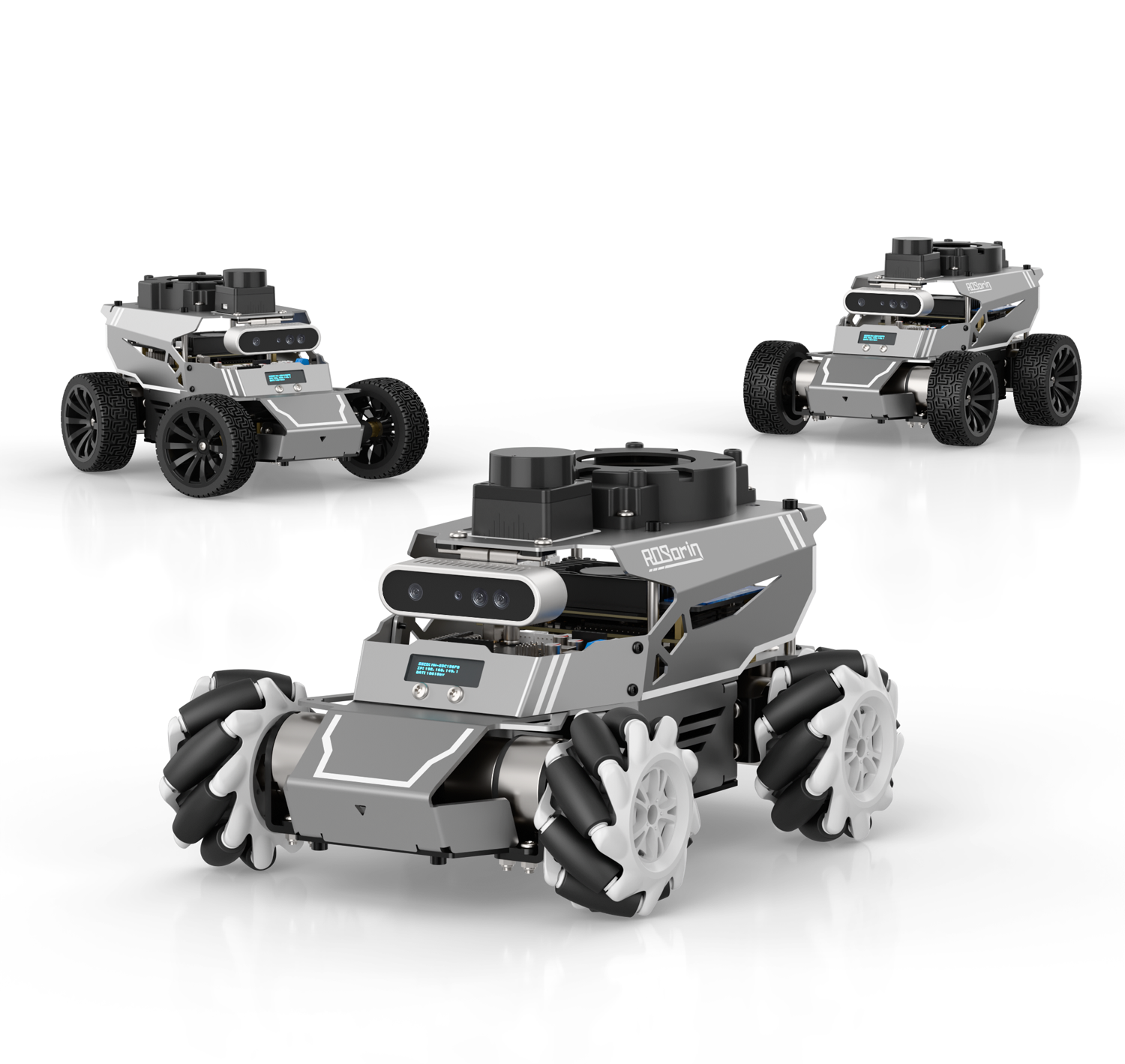
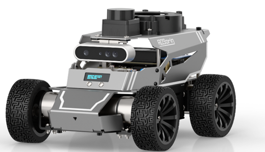
ROSOrin is a versatile ROS-based platform designed for teaching and research. Its patented all-in-one modular chassis makes it easy to switch between Mecanum, Ackermann, and differential drive setups, letting you adapt to different movement modes in seconds. The chassis features a swing arm suspension that keeps all four wheels evenly balanced. This ensures smooth operation on uneven surfaces, prevents wheel slip from affecting motor encoders, and keeps movement stable and efficient. Powered by high-performance hardware—including NVIDIA Jetson, Raspberry Pi 5, LiDAR, 3D depth camera, a 6-microphone array, and an AI voice interaction module—ROSOrin supports a wide range of applications: robot motion control, SLAM navigation, path planning, 3D object recognition, tracking and obstacle avoidance, multi-point navigation, gesture interaction, voice interaction, and sound source localization. With multimodal large AI models and the 6-microphone array, ROSOrin can understand its surroundings, plan actions, and carry out tasks intelligently, opening the door to advanced embodied AI applications.
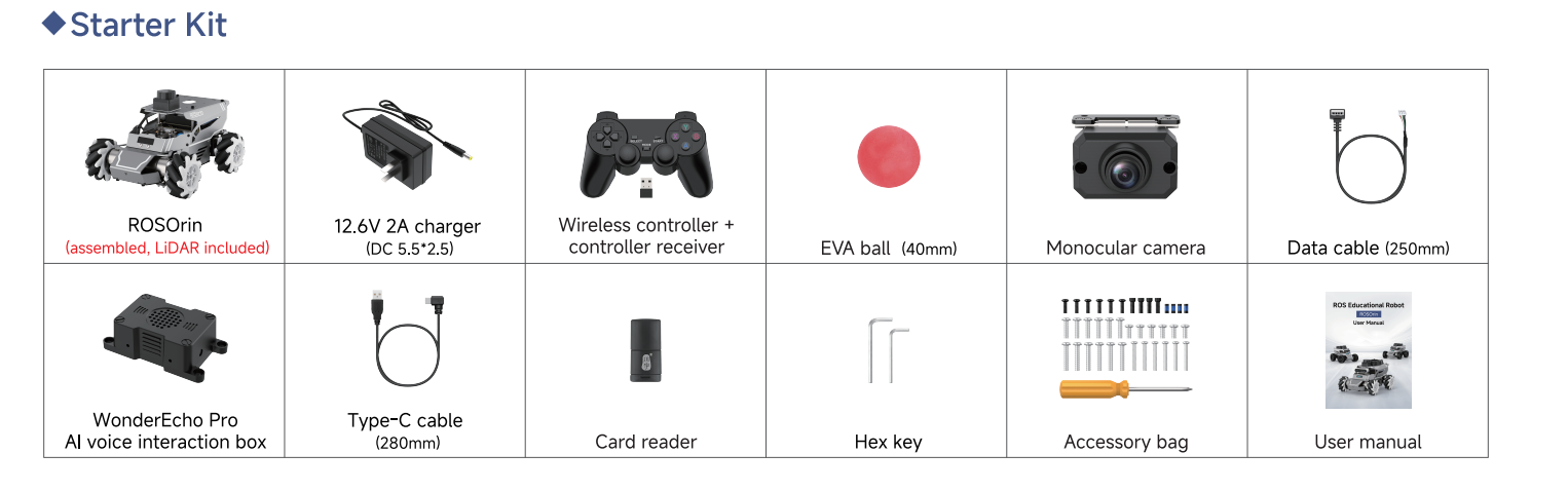
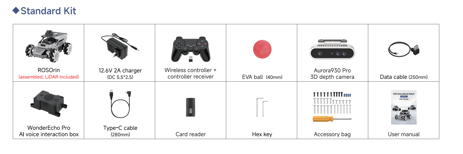
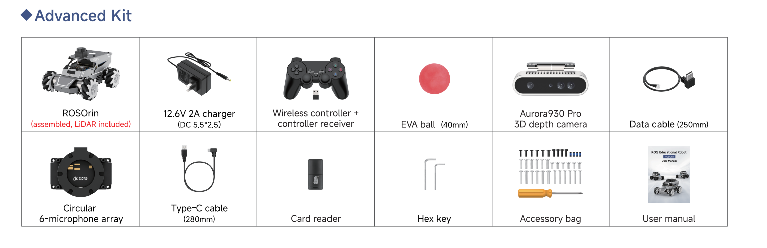
1.1.1 Packing List
The included components of the ROSOrin robot are listed in the table below.
1.2 Accessories Installation and Startup Preparation
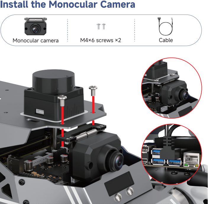
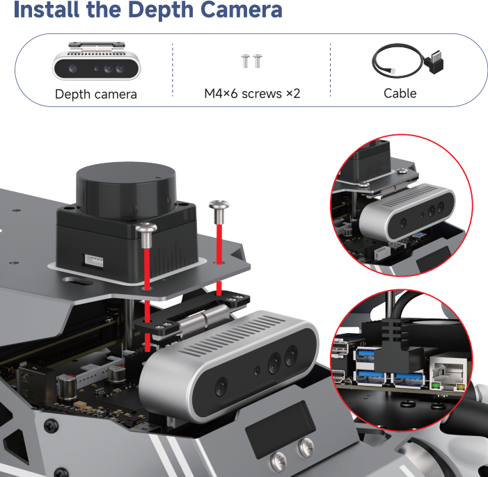
1.2.1 Camera Installation
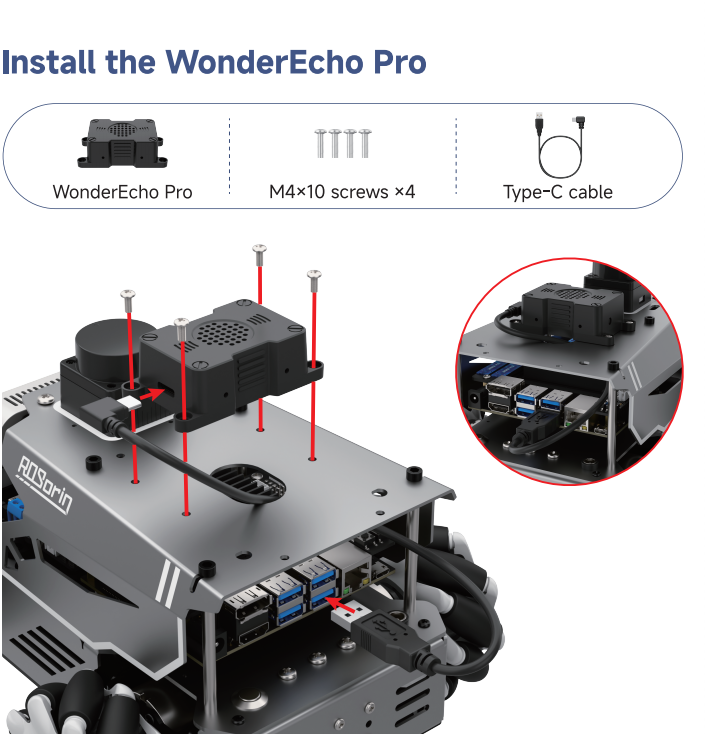
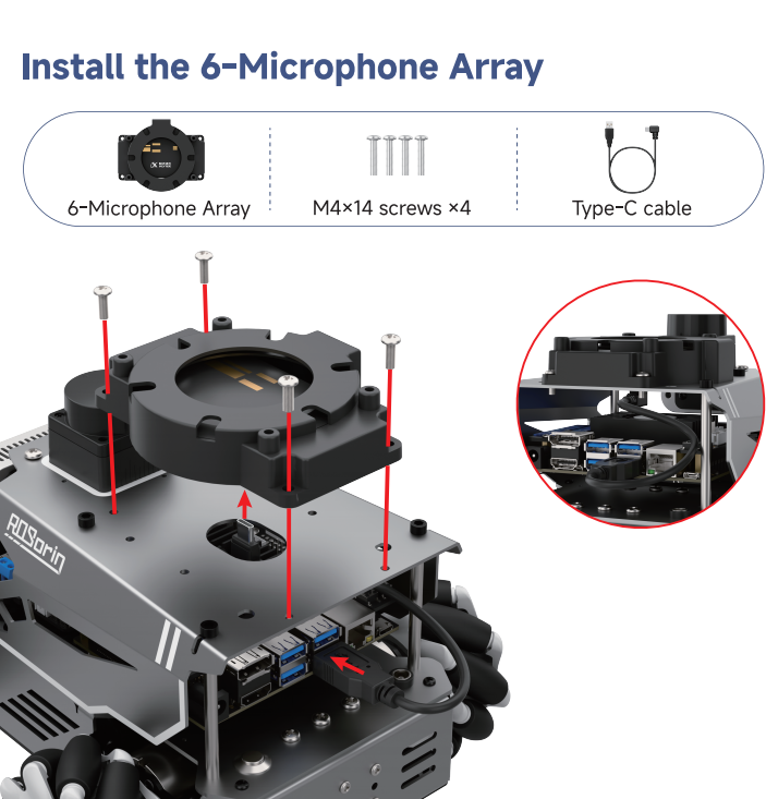
1.2.2 Voice Module Installation
1.2.3 Wiring Instruction
1.2.3.1 Jetson Nano Wiring
| Serial No. | Access Module |
|---|---|
| 1 | Power Supply Port |
| 2 | HDMI Port |
| 3 | LiDAR |
| 4 | Monocular/Depth Camera |
| 5 | STM32 Controller |
| 6 | AI Voice Interaction Box/6-Microphone Array |
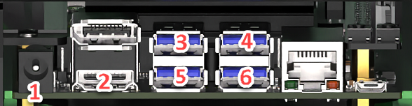
1.2.3.2 Jetson Orin Nano / Orin NX Wiring
| Serial No. | Access Module |
|---|---|
| 1 | Jetson Orin Nano/Orin NX Controller Power Supply Port |
| 2 | DC Port |
| 3 | LiDAR |
| 4 | Monocular/Depth Camera |
| 5 | STM32 Controller |
| 6 | AI Voice Interaction Box/6-Microphone Array |
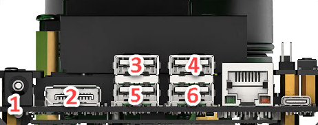
1.2.3.3 Raspberry Pi 5 Wiring
| Serial No. | Access Module |
|---|---|
| 1 | LiDAR |
| 2 | Monocular/Depth Camera |
| 3 | STM32 Controller |
| 4 | AI Voice Interaction Box/6-Microphone Array |
| 5 | Ethernet Port |
1.2.4 Ackermann Chassis Switch
Use an M3 hex screwdriver to remove all five M3 hex screws from the Mecanum chassis.
Take the Ackermann chassis part and attach it to the robot using the M3 hex screws.
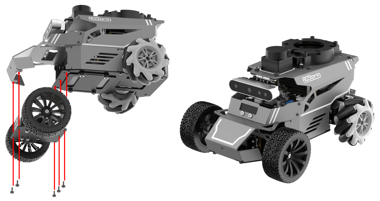
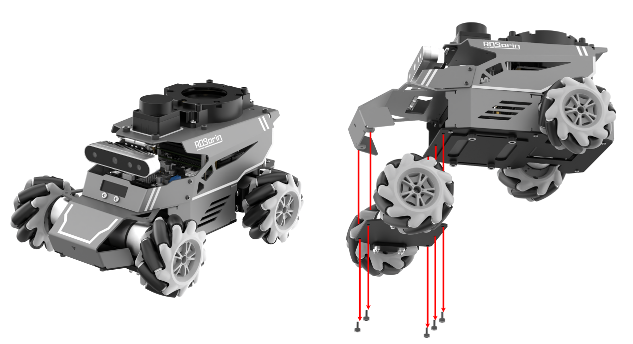
Remove the M4×10 screws inside the wheels, then take out the black M2.5×6 screws from the couplers, and detach both Mecanum wheels.
Mount the Ackermann wheels using the same black M2.5×6 and M4×10 screws. Once installed, the assembly is complete.

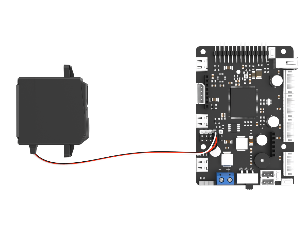
Note
After assembling the Ackermann chassis, connect the servo to the position shown in the diagram for proper operation.
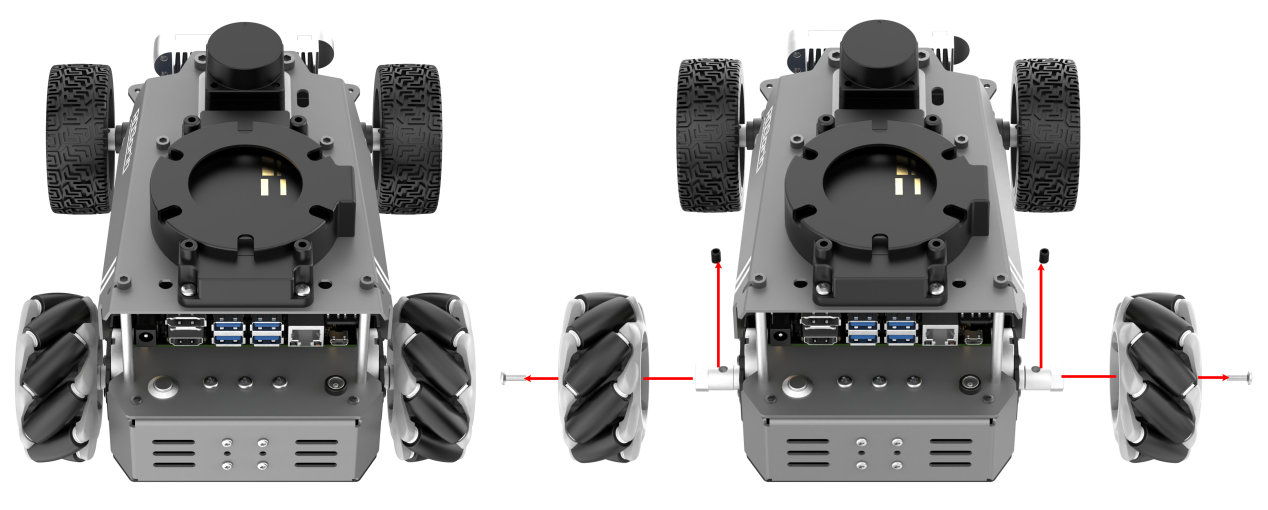
1.2.5 Differential Drive Chassis Switch
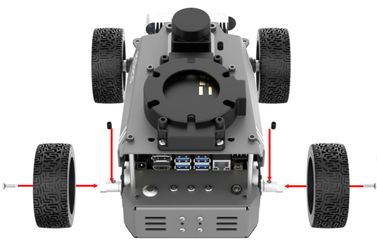
Remove the M4×10 screws inside the wheels, then take out the black M2.5×6 screws from the couplers, and detach all the Mecanum wheels.
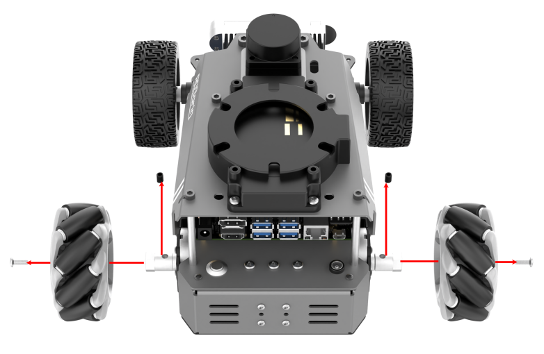
Mount the four differential wheels using the same black M2.5×6 and M4×10 screws. Once installed, the assembly is complete.
1.3 Initial Setup and Power-On
In this section, you will learn about the startup sequence of the robotic arm and verify the functionality of each module. After completing this step, you can proceed to the following chapters to explore app control and wireless controller control.
1.3.1 Power-On Preparations
To ensure stable operation, recharge the battery promptly when its voltage drops below 10 V.
Do not place the robot near the edge of a table to avoid accidental falls and damage.
Always operate the robot on a flat, stable surface.
Maintain a safe distance from the robot before powering on to prevent accidental contact with moving parts.
Before powering on, ensure that the wiring is correct and the robot is fully charged. If the robot doesn’t power on, check the wiring of each module.
1.3.2 Power-On Status
Ensure that the robot’s power switch is not turned on.
Remove the hex screws from the bottom of the robot and open the metal cover.
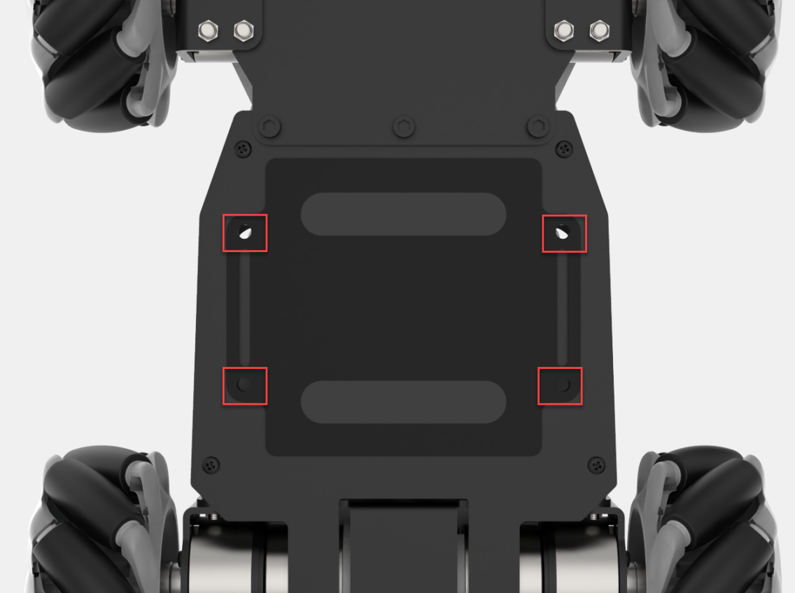
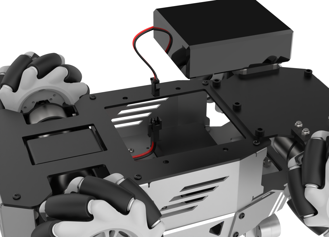
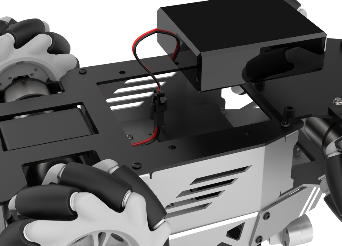
Make sure to connect the red wire to the red terminal and the black wire to the black terminal as shown in the figure below. The connectors are designed with a reverse polarity prevention feature. Do not force them if they don’t match, you may rotate the connector and try again. Then, reassemble the metal cover.
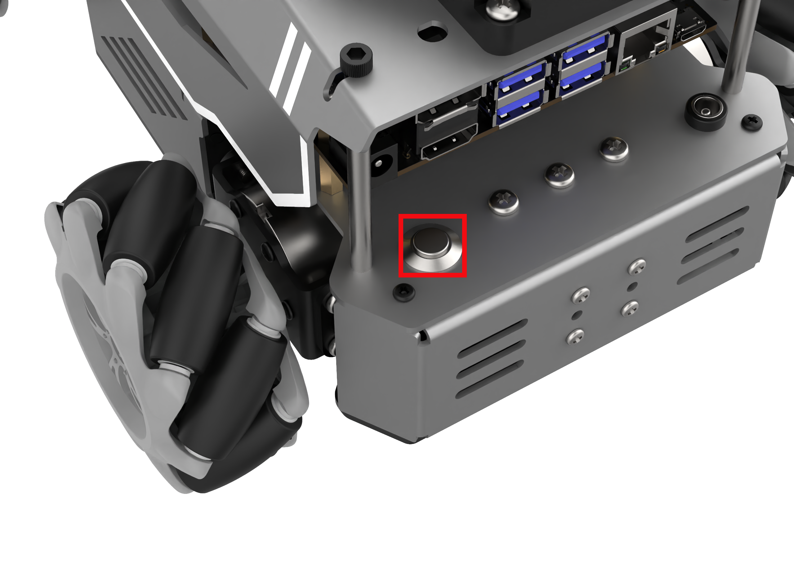
Place the robot on a flat, smooth surface and press the switch located on the rear left side of the robot.
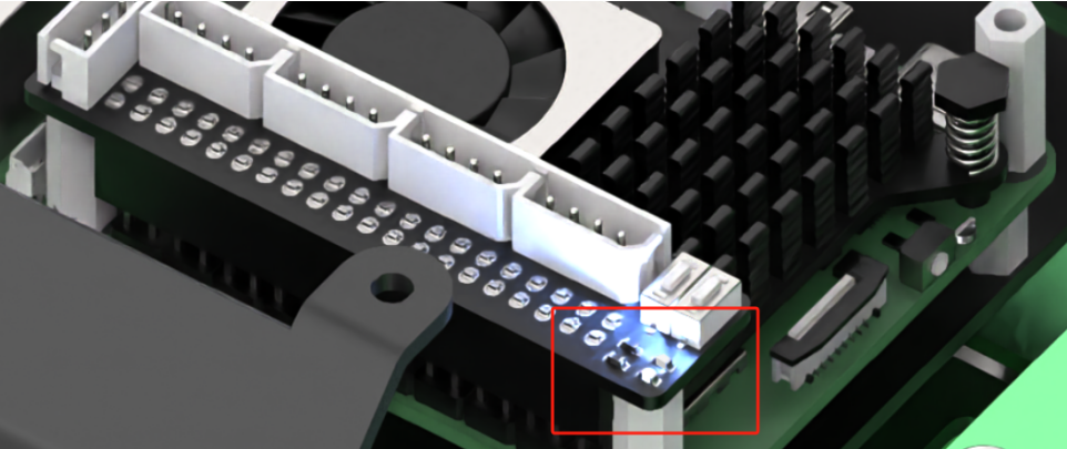
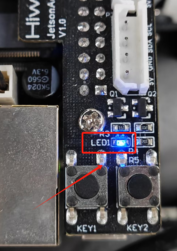
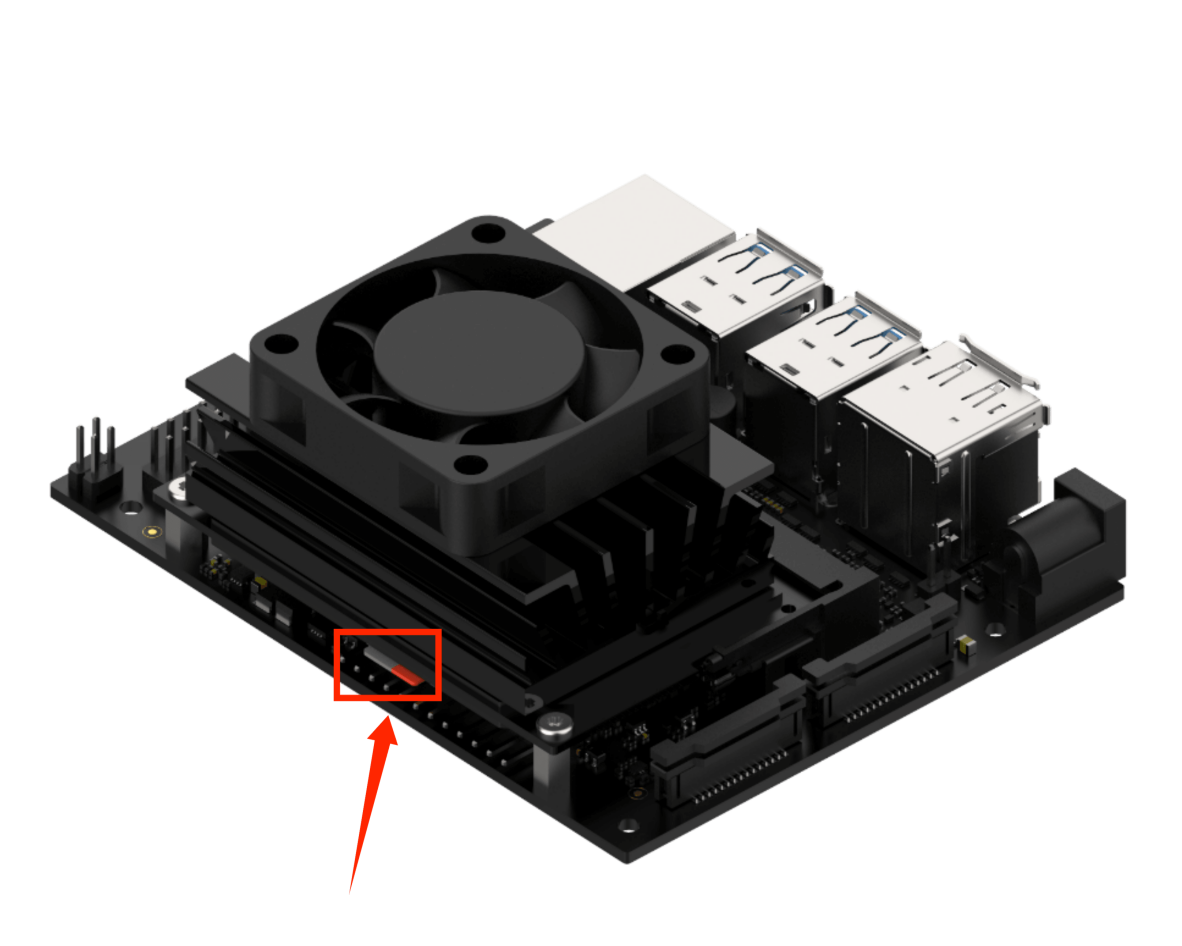
The blue LED1 at the lower right of the expansion board will light up and start blinking. At this stage, only the network configuration service is running, the ROS system and other services have not yet fully started. Wait until the buzzer emits a short beep — this indicates the system has finished booting.
(1) The LED locations on the Jetson controllers are shown in the diagram below.
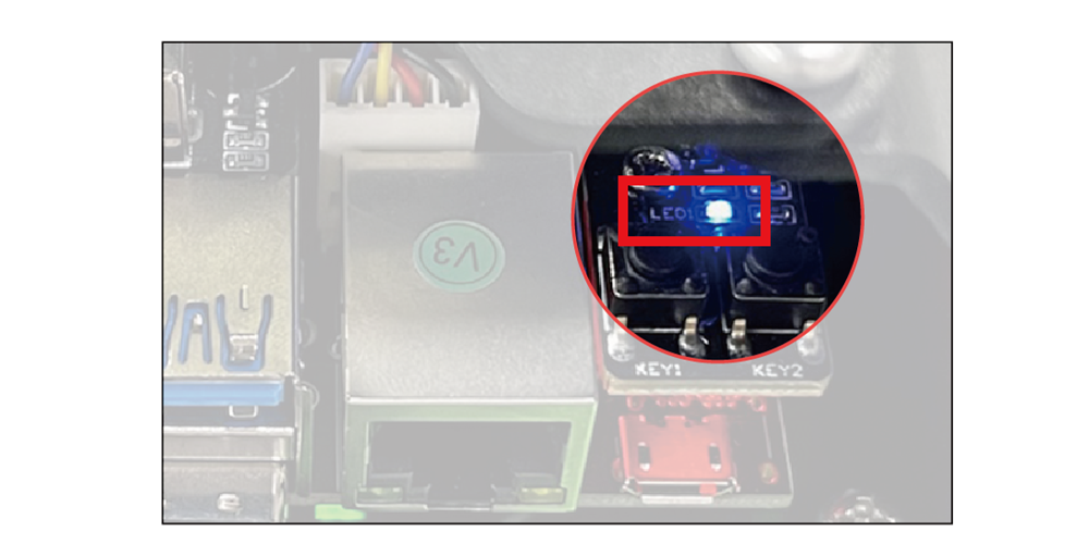
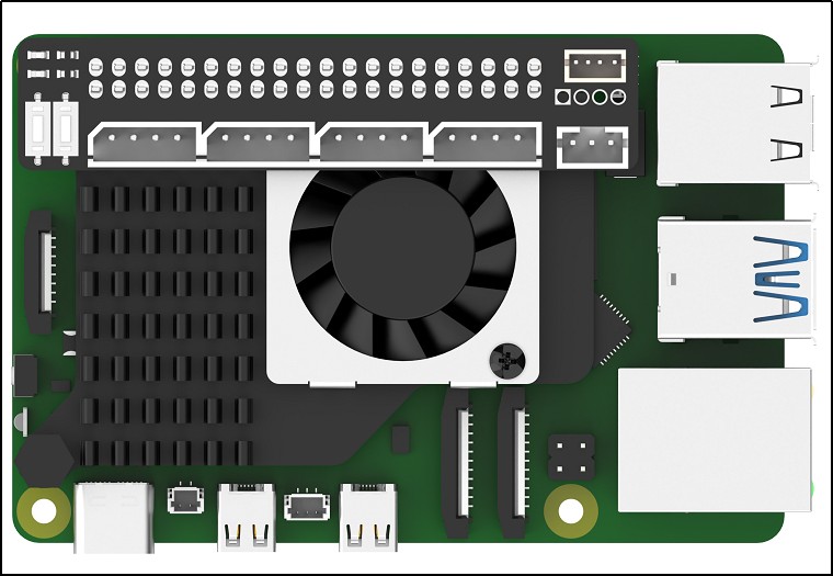
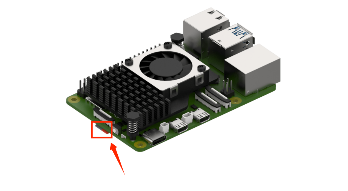
(2) The LED locations on the Raspberry Pi 5 controller are shown in the diagram below.
By default, the device is configured in AP direct-connect mode. After startup, a Wi-Fi hotspot beginning with “HW” will appear. To connect via mobile app or remote desktop, enter the default password: hiwonder.

Note
If the hotspot does not appear after startup, troubleshoot as follows:
Verify that all steps in the Power-On Status section have been followed.
If LED1 stays solid blue instead of blinking, the system may be in LAN mode. Long-press the KEY1 button on the expansion board for 5–10 seconds. If LED1 starts blinking, the HW Wi-Fi hotspot has been re-enabled.
If LED1 does not blink after pressing KEY1, the system may not detect the SD card or SSD. Remove and reinsert the SD card.
If the LED remains solid after reinserting, the SD card may be corrupted, or the system image has not been flashed for kits without a controller. You may replace or reflash the image to the SD card.
If the issue persists, the Raspberry Pi 5 controller or Jetson controller may be faulty. Please contact customer support for assistance.
The following table outlines how to test each hardware module.
| Module | Verification Steps | Result |
|---|---|---|
| Extension Board LED | Observe the LED's lighting and flashing behavior | By default, the LED is blue and flashing in AP direct connection mode, indicating that network service configuration is complete. |
| Buzzer | Check for a short beep | A short beep from the buzzer indicates that the onboard hardware of the extension board is functioning normally. |
| LiDAR | Observe the rotation | The built-in blue LED of the LiDAR lights up and rotates continuously. |
| KEY1 on Extension Board | Switch network status | After connecting to the STA local network mode via the mobile app, press and hold the KEY1 button to check if the LED1 indicator flashes. |
| Microphone, Sound Card, Speaker | Say Hello Hiwonder to the robot after powering on | There is feedback to the wake word, and the speaker plays the response "I'm here." Only available for the kits that include a voice device. |
| Depth Camera | 1. Open the app and connect to the robot. 2. Open the "Robot Control" function and check the real-time feed from the depth camera. |
Displays the real-time feed and rotates. |
| STM32 Controller + Encoder DC Gear Motor | After powering on, use the Robot Control function via the wireless controller or the app. | The robot moves normally. |
1.4 Battery Usage and Charging Instructions
Since the robot must be powered off during transportation and the battery cannot be fully charged, you need to connect the battery cable to charge the battery before first use. Charging the battery from 10 V to about 12.3 V takes approximately three hours.
Note
When the battery voltage falls below 10V, the buzzer will emit a “beep-beep-beep” low voltage warning. If the battery is low, turn off the robot immediately and charge the battery according to the recommended charging procedure.
1.4.1 Lithium Battery Care
1. Always use the dedicated charger included with the kit to charge the robot. Turn off the robot while charging. Do not operate the robot and charge the battery at the same time.
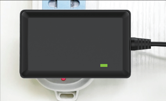
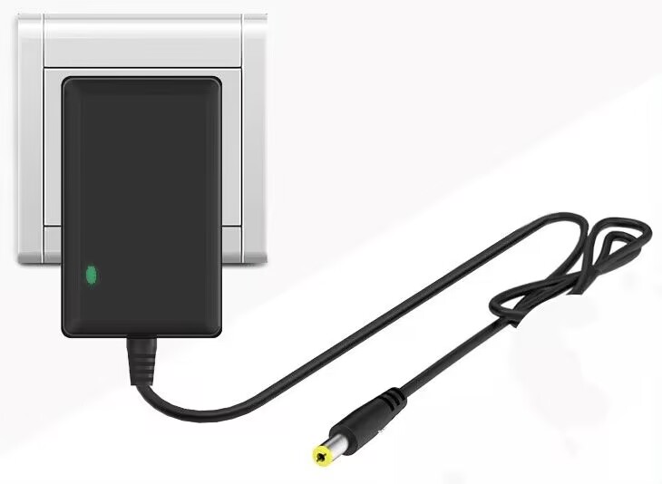
2. When the charger is connected to the battery but not plugged into a power outlet, the indicator light shows green. During charging, the indicator light turns red. When fully charged, it will return to green.
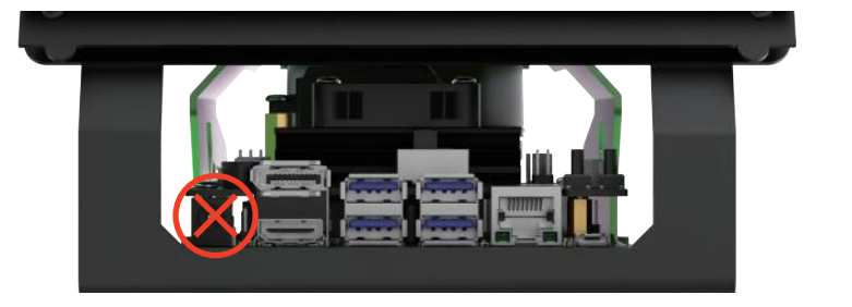
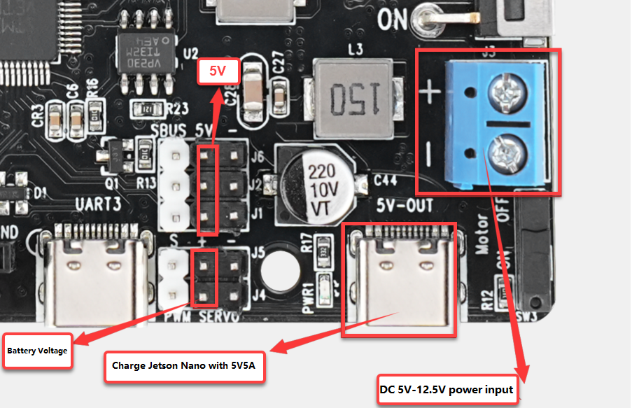
Do not plug the charger directly into the DC power input on the Jetson controller, as shown in the diagram below, as it may damage the controller. The image is for reference only.
4. Disconnect the charging cable promptly after charging to avoid overcharging and battery damage.
5. To ensure stable robot performance, recharge the battery when its voltage drops below 10 V, indicated by a beeping buzzer on the expansion board.
6. If the robot will not be used for an extended period, fully charge the battery and disconnect the battery cable.
7. Store the battery in a cool, dry place to prevent reduced lifespan due to overheating or moisture. Do not hit, throw, or step on the battery.
8. Do not use the battery in environments with strong static electricity or magnetic fields, as this may damage its safety protection circuitry.
9. Do not plug the battery directly into a wall socket. Do not short-circuit the battery terminals with metal objects.
10. Over-discharging may prevent the battery from recharging and could render it unusable. For long-term storage, fully charge the battery first.
11. Do not attempt to modify, solder, or alter the battery or charger in any way.
12. Keep batteries away from high temperatures and liquids to avoid overheating, fire hazards, or moisture-related damage.
Important Notice: Hiwonder is not responsible for any damage, economic loss, or safety incidents resulting from improper use of the product that does not follow the instructions outlined in this manual.
1.4.2 Charging Instructions
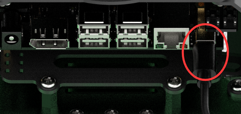
The power input is located on the right side at the back of the robot. Plug in the charger to begin charging.
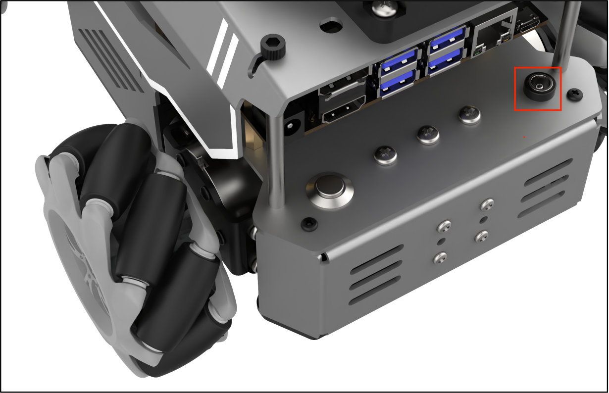
Check the indicator light on the charger to monitor the charging status. The indicator shows red while charging and turns green when charging is complete.
Note
After charging is complete, unplug the charger promptly to prevent overcharging.
1.5 App Installation and Connection
Note
Please grant all permissions requested during installation to ensure the app functions properly.
Turn on your phone’s GPS and Wi-Fi before opening the app.
This section explains how to install the WonderAI app to control the robot.
1.5.1 App Installation
The app installation package is located in the directory:
2 Softwares\1. App Installation Package. Transfer the APK file to your phone and install it.
Or scan the QR code below to download the app.

1.5.2 Connection Modes
After installing the app, you can proceed to connect the robot. The robot supports two network modes:
AP Mode (Direct Connection): The controller creates a hotspot that your phone can connect to directly, but no Internet access in this mode.
STA Mode (LAN Connection): The controller connects to a specified Wi-Fi network, and Internet access is available in this mode.
By default, the robot starts in AP direct connection mode. Regardless of whether the user chooses AP direct connection or STA LAN mode, the robot’s features remain the same.
Tip: We recommend starting with the AP direct connection mode to quickly explore and experience the robot’s functions. You can switch to LAN mode later based on your specific needs.
1.5.2.1 AP Mode Connection (Must Read)
Note
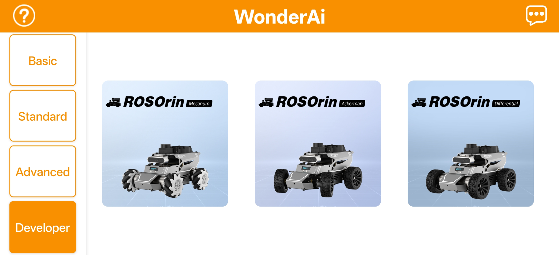
This section demonstrates the connection using the Android device and the Mecanum wheel version. If switching to the Ackermann or differential drive versions, refer to the Changing Chassis Type section first, then follow this procedure for connection.
Open the WonderAi app and select Developer > ROSOrin Mecanum.
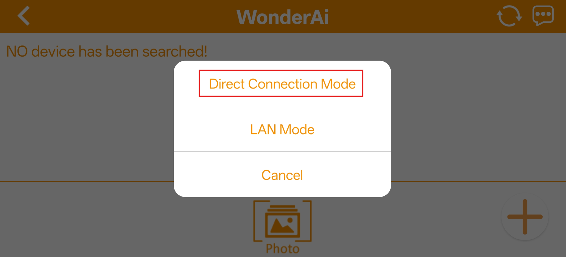
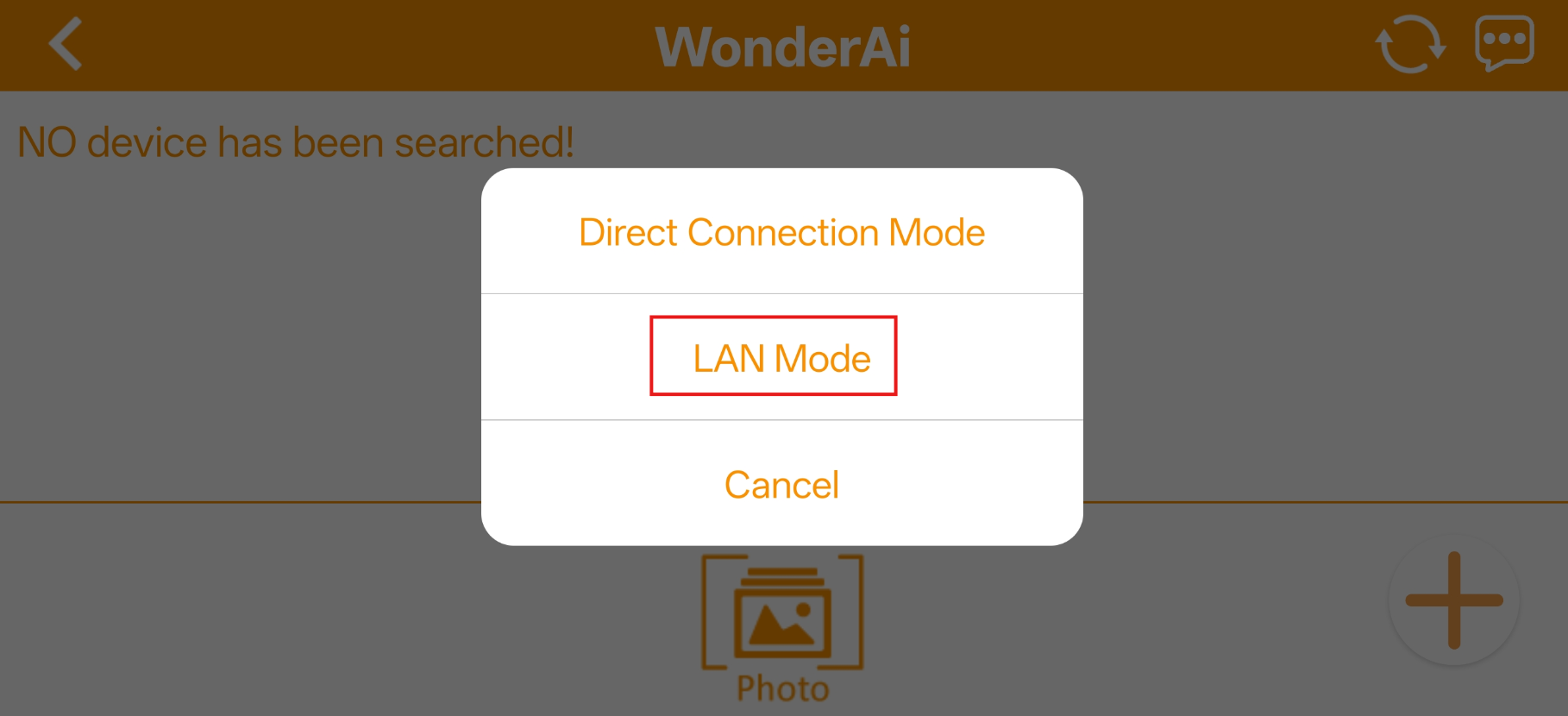
Tap the + button in the bottom-right corner and choose Direct Connection Mode.
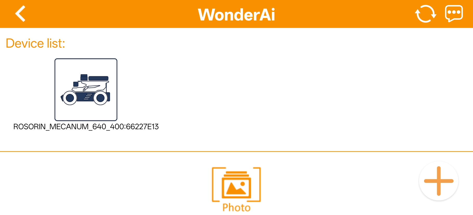
3. Search for the robot’s WiFi network. The hotspot name starts with HW, and the password is hiwonder.
4. Return to the app, tap the corresponding robot icon, and enter the mode selection screen.
Note
If a message pops up saying “Network is unavailable, continue?”, tap “Keep Connection” to proceed.
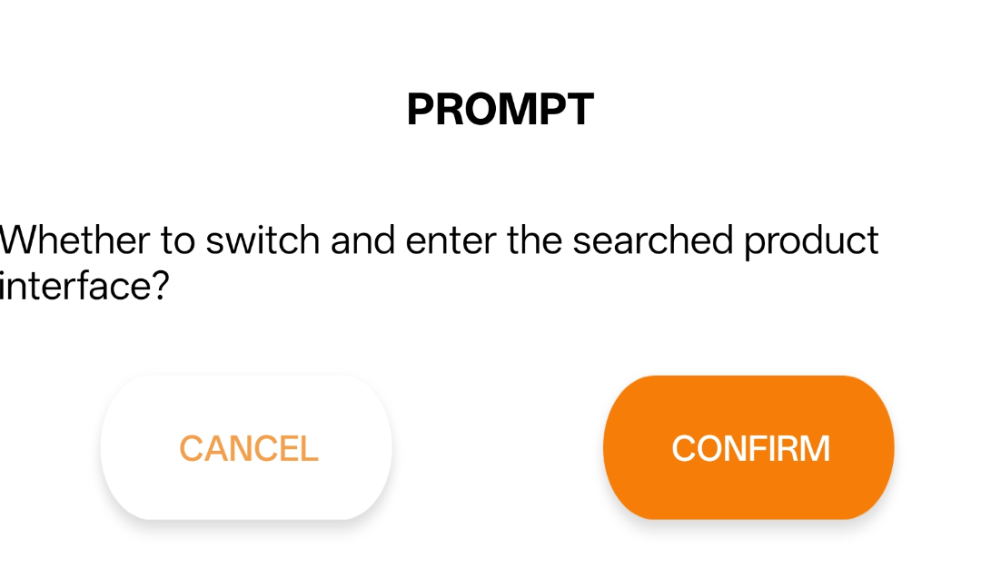
If a message appears saying Whether to switch and enter the searched product interface?, it means the wrong product was selected in Step 1. Tap Confirm to automatically switch to the correct version’s mode selection screen.
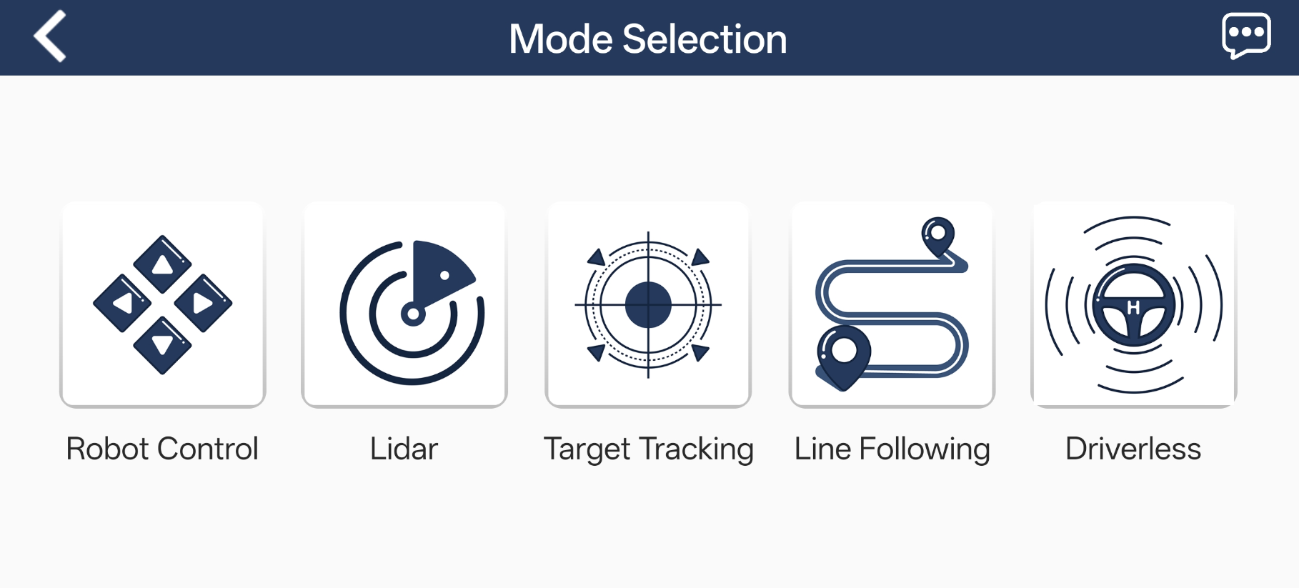
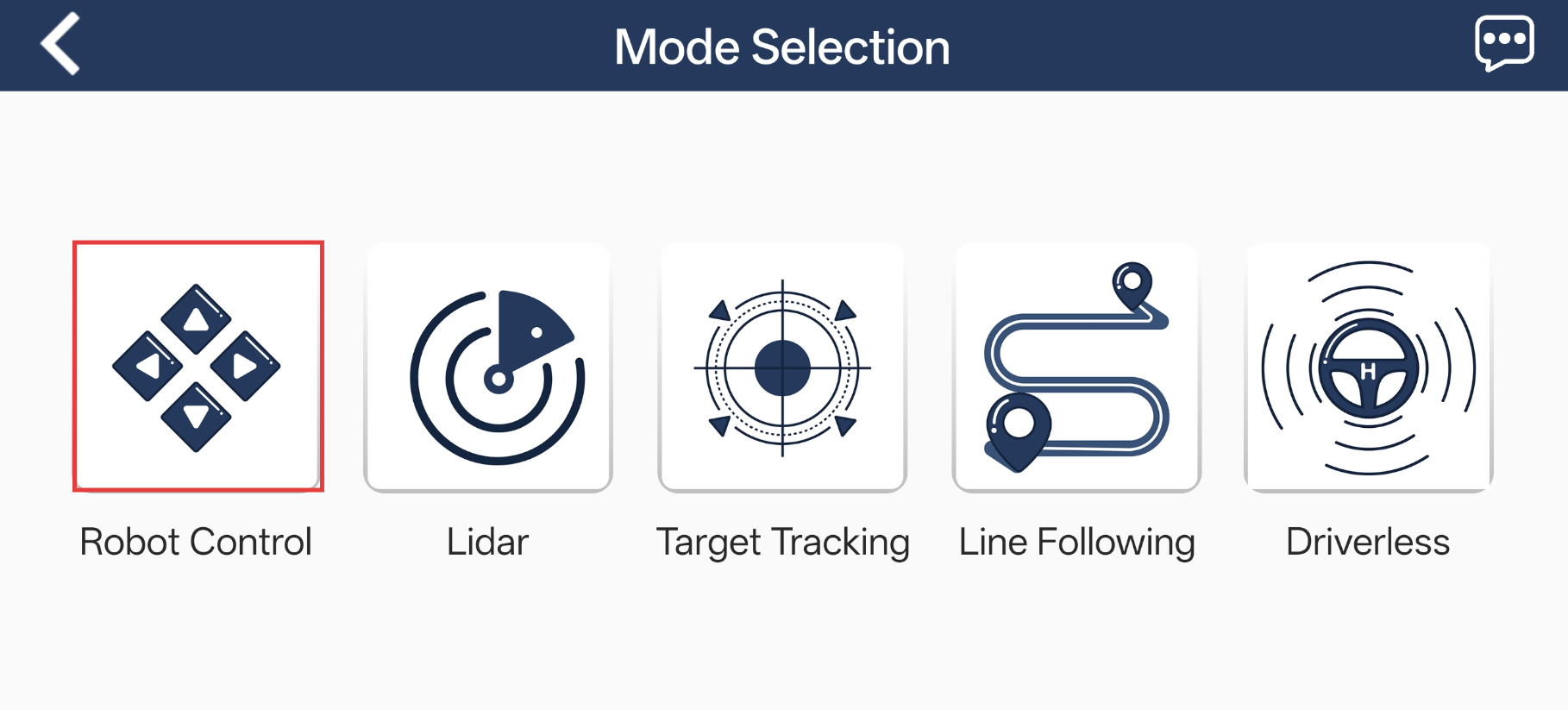
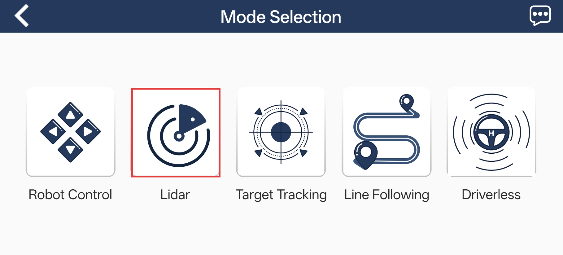
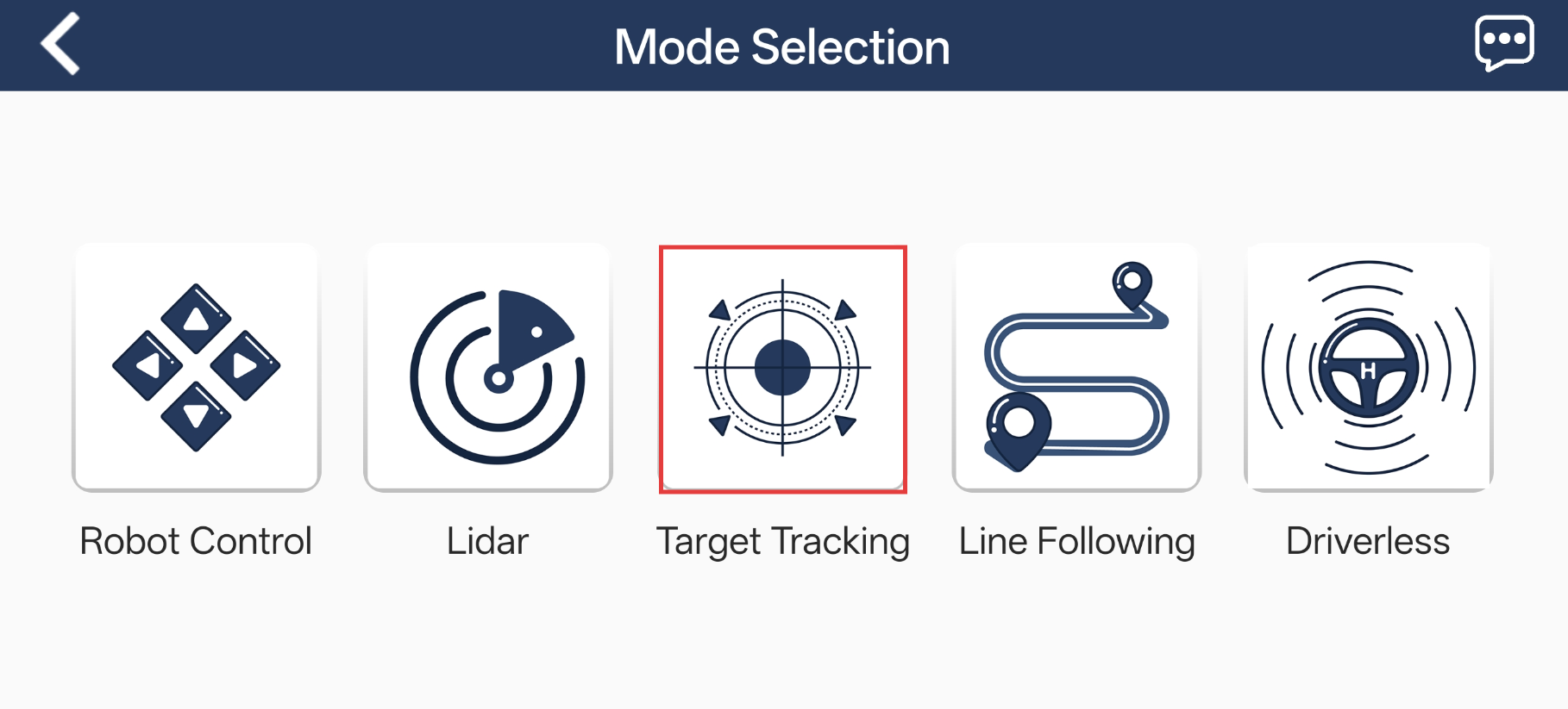
The mode selection interface is shown below.

1.5.2.2 LAN Mode Connection (Optional)
Note
After setting the robot to LAN mode, it will no longer broadcast a WiFi network starting with HW.
First, connect your phone to a 5G Wi-Fi network. For example, connect to Hiwonder_5G. A dual-band router, when configured with separate SSIDs for each band, will have distinct default Wi-Fi names for the two frequencies.
Open the WonderAi app and select Developer > ROSOrin.
Tap the + button in the bottom-right corner and choose LAN Mode.
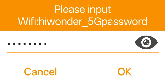
The app will prompt you to enter the Wi-Fi password for the network you’re connected to. Make sure you enter the correct password, a wrong password will prevent the connection. After entering the password, tap OK.
Tap Go to connect device hotspots to switch to the Wi-Fi settings.
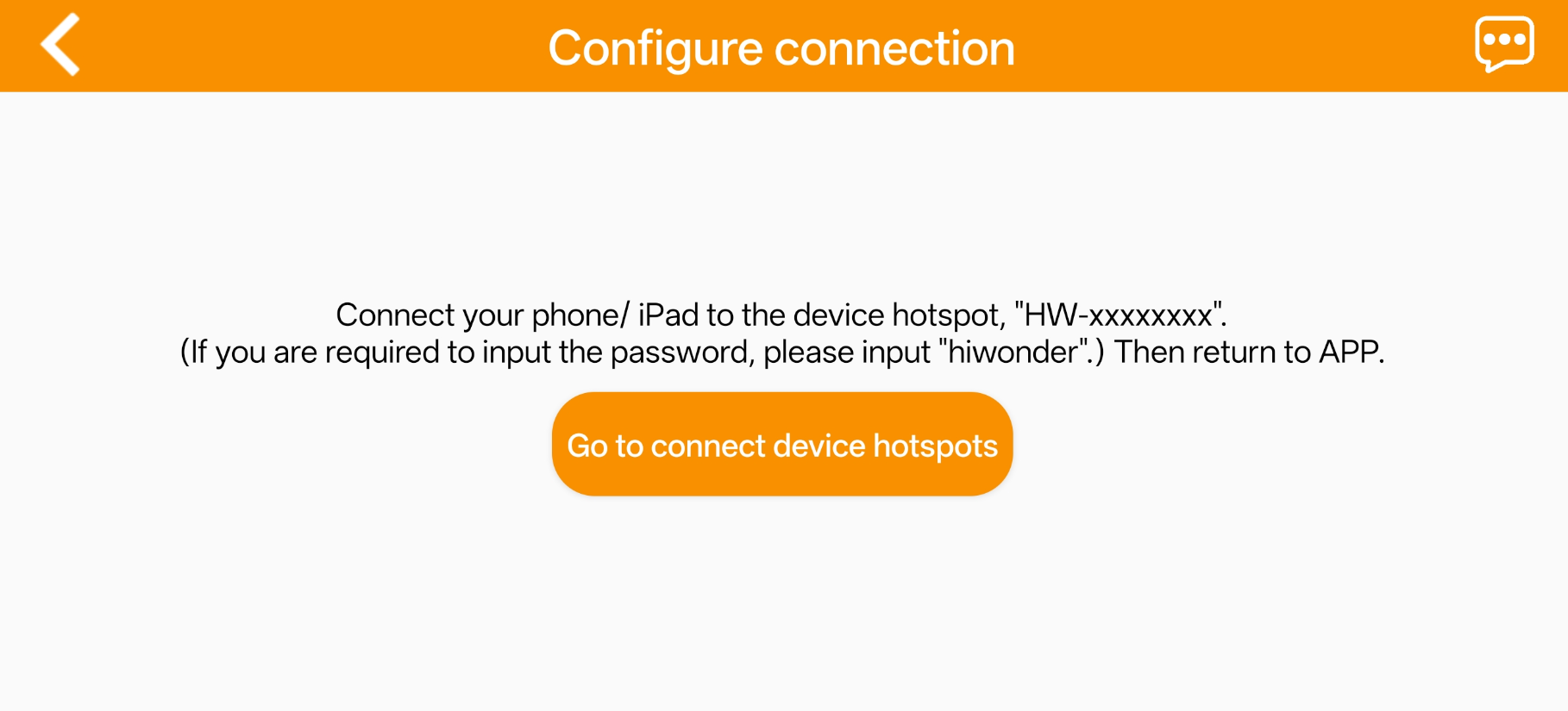
6. In the Wi-Fi list, find the hotspot starting with HW, and connect to it using the password hiwonder. After connecting, tap the Back icon to return to the app.
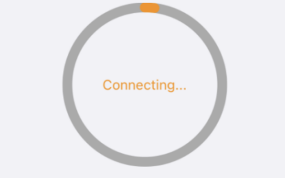
7. The app has started connecting to the robot.
8. After a few seconds, the robot’s icon and name will appear on the main screen. The LED1 indicator on the expansion board will stay on.
Press and hold the robot’s icon to display its current IP address.
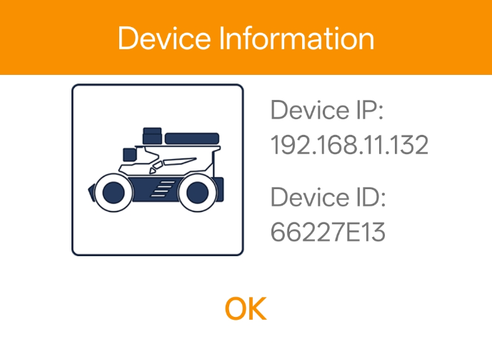
The IP address can be entered in the remote desktop client to establish a connection. For detailed connection instructions, refer to section 1.7 Development Environment Setup.
1.5.3 App Control
You can control the robot via the WonderAi app and explore its AI vision features. This section explains the operation of each function within the app. This section demonstrates the process using an iOS device, but the same method applies to Android devices.
1.5.3.1 Preparation
First, power on the robot. For details on startup status, refer to section 1.3.2 Power-On Status.
Next, install the WonderAi app and connect the robot. For step-by-step instructions, see section 1.5.1 App Installation.
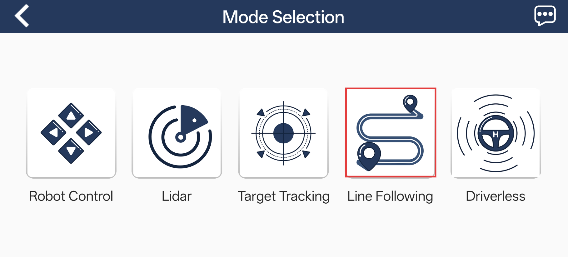
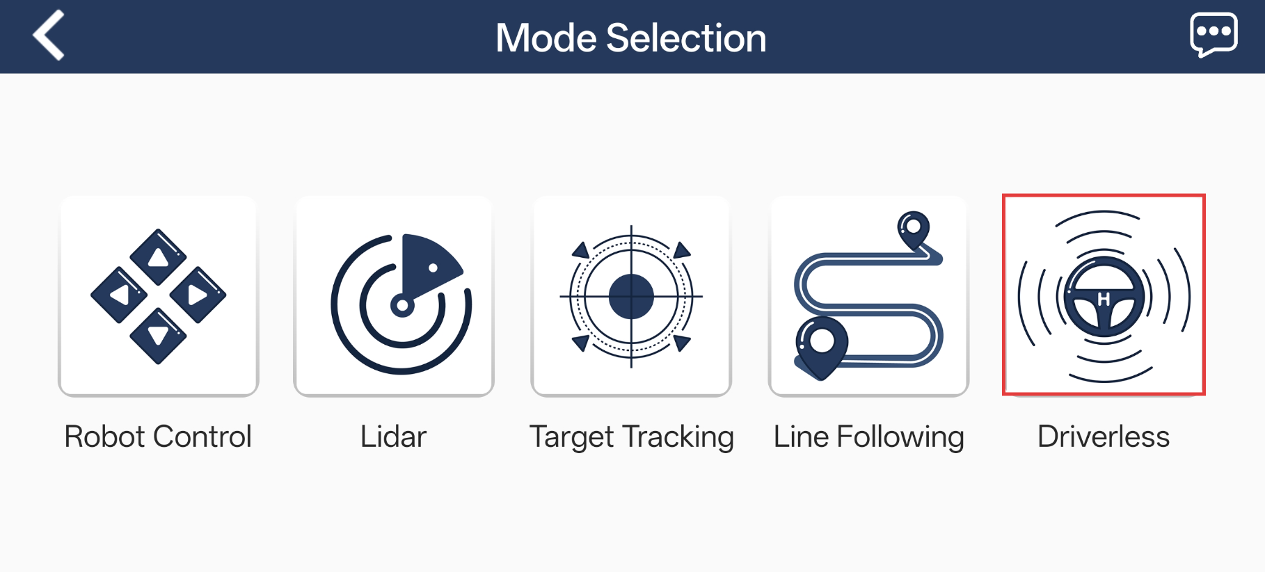
1.5.3.2 App Modes
The app provides five modes, including Robot Control, Lidar, Target Tracking, Line Following, and Driverless.
The table below offers a detailed overview of each mode.
| Icon | Mode | Description |
|---|---|---|
 |
Robot Control | Control the movement of the robot. |
 |
LiDAR | Provides three functions: LiDAR obstacle avoidance, LiDAR following, and LiDAR guarding. |
 |
Target Tracking | Select the color of the target object, and the robot will track it. |
 |
Line Following | Lay down a line and set its color as the target recognition color. The robot will follow the line. |
 |
Driverless | Experience the autonomous driving feature. |
1.5.3.3 Robot Control
Tap Robot Control on the mode selection screen to enter the control interface.
The interfaces for the Mecanum/Differential and Ackermann versions differ slightly. The Mecanum/Differential interface is shown below:
Mecanum/Differential Drive Chassis
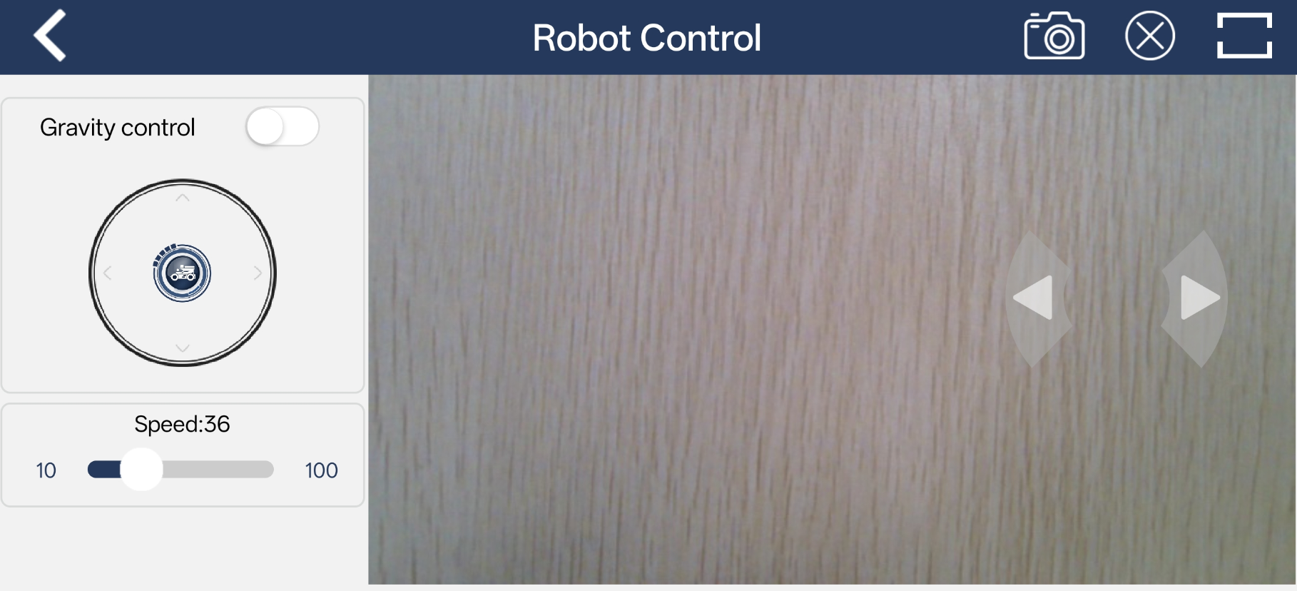
1. The buttons on the left, from top to bottom, correspond to gravity control, forward/backward movement, and speed adjustment.
2. The center displays the feedback video.
3. The buttons on the right, from top to bottom, control steering.
4. The top menu icons allow ![]() screenshot,
screenshot, ![]() hide navigation bar, and
hide navigation bar, and ![]() switch to full-screen mode. This function is typically used alongside the wireless controller.
switch to full-screen mode. This function is typically used alongside the wireless controller.
5. Clicking the full-screen button ![]() displays the feedback video in full screen, which is useful for monitoring real-time video while controlling the robot with the controller.
displays the feedback video in full screen, which is useful for monitoring real-time video while controlling the robot with the controller.

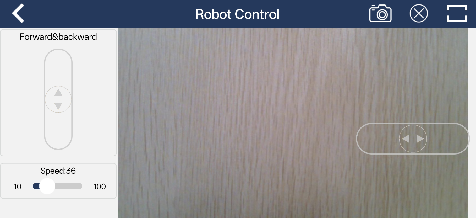
Ackermann Chassis
For more details:
1. The buttons on the left, from top to bottom, control forward/backward movement and speed adjustment.
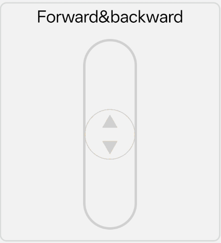
The forward/backward slider controls the robot chassis movement.
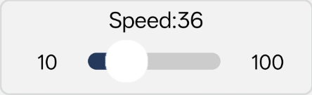
Dragging the slider adjusts the speed of the robot.
2. The right side displays the feedback video from the depth camera, serving as the video transmission function.

3. Within the feedback video panel, the buttons from top to bottom control the front wheel steering.

For the Ackermann chassis, dragging the horizontal slider adjusts the rotation of the front wheels.
1.5.3.4 LiDAR
Note
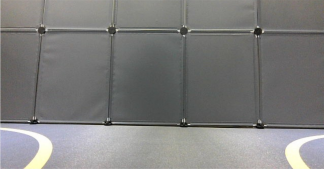
Before stating the feature, ensure that the robot is on a spacious surface with enough room to move freely.
In LiDAR Obstacle Avoidance and LiDAR Following modes, the detection range is a 90° fan-shaped area in front of the robot.
The LiDAR Guard mode is not supported when using the Ackerman chassis.
Interface Overview
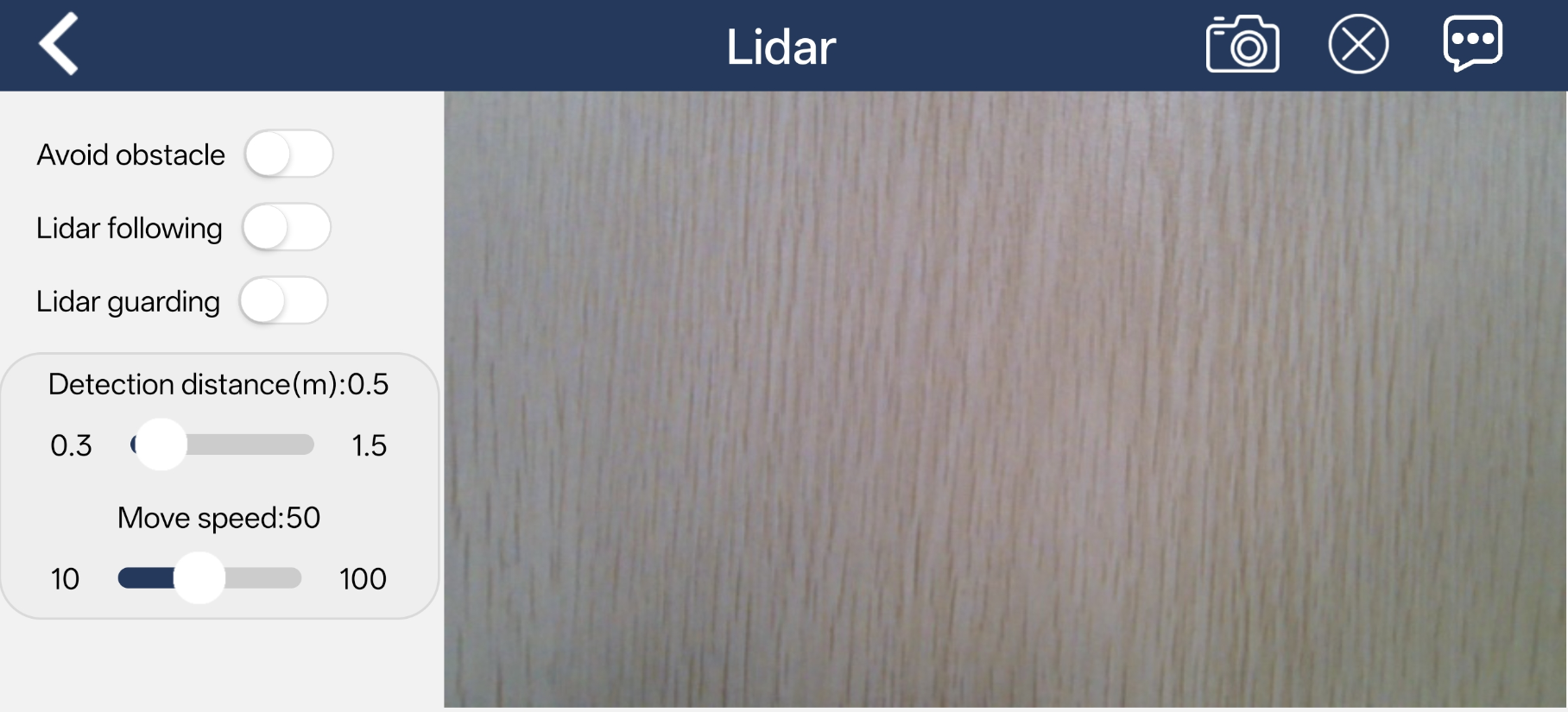
Tap LiDAR on the mode selection screen to enter the control interface.
The LiDAR mode includes three features: Avoid obstacle, Lidar following, and Lidar guarding. This interface is divided into two sections:
In the left panel, enable or disable the feature.
In the right panel, display the live video feed from the camera.
Function
| Icon | Function Description |
|---|---|
| Turn on/off LiDAR obstacle avoidance mode. | |
| Turn on/off LiDAR following mode. | |
| Turn on/off LiDAR guarding mode. | |
 |
Display the current camera feed. |
Operating Steps and Effects
Avoid obstacle
The robot continuously moves forward. When an obstacle is detected, it automatically changes direction to avoid it.
Lidar following
When an obstacle is detected, the robot adjusts its position to maintain a safe distance from the object.
Lidar guarding
When an obstacle is detected, the robot turns to face the object.
1.5.3.5 Target Tracking
Note
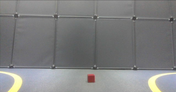
Place the target object on the same surface as the robot and move it in a horizontal direction, which ensures a smoother tracking experience.
Choose an appropriate color range for target extraction. If the range is too wide, unwanted colors may be included. If the range is too narrow, the target may be lost. Also, avoid having objects with similar colors to the target in the camera’s view.
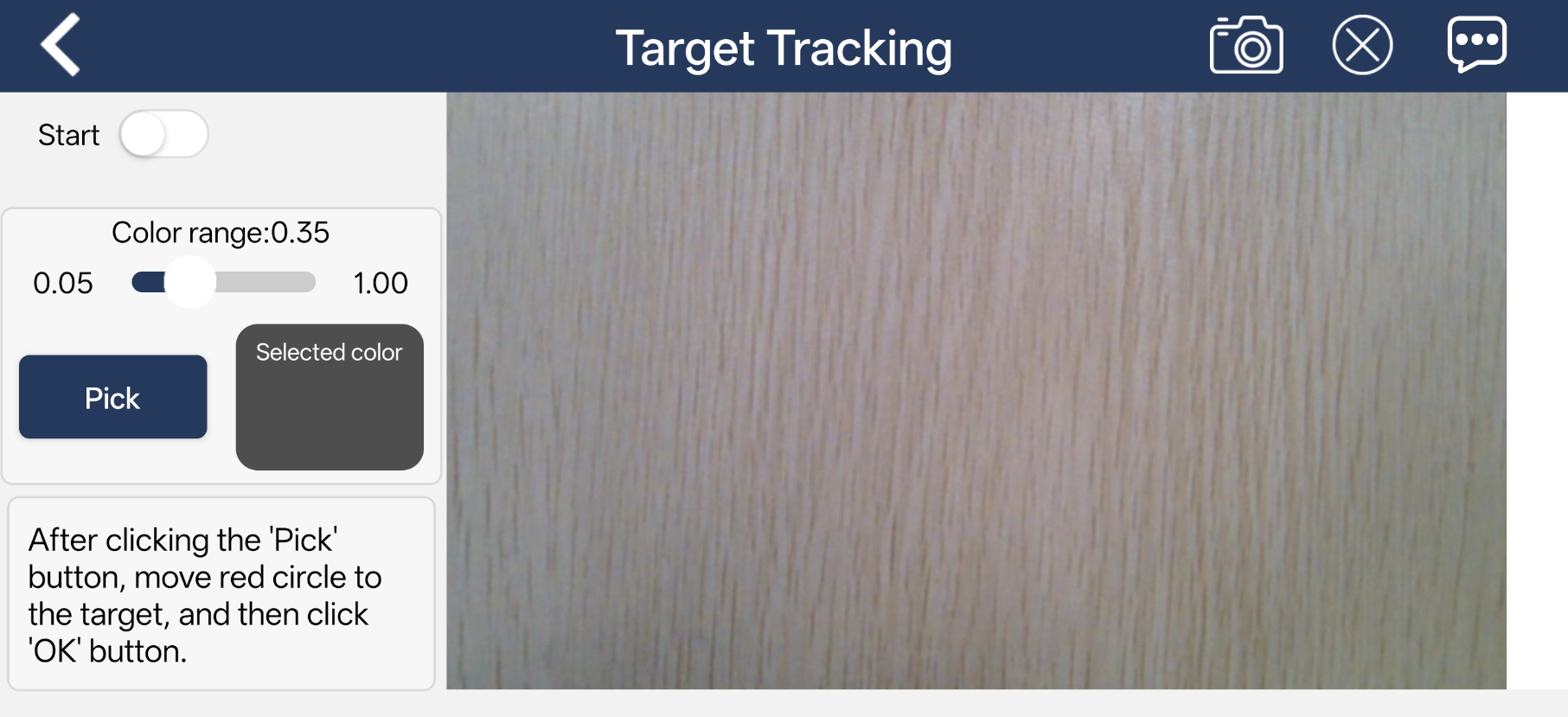
Interface Overview
Tap Target Tracking on the mode selection screen to enter the control interface.
This interface is divided into two sections:
The left panel contains the mode switch and color extraction tools.
In the right panel, display the live video feed from the camera.
Function
| Icon | Function Description |
|---|---|
 |
Turn on/off the mode. |
| Adjust the color threshold range, with a value range of 0.05-1.00. | |
 |
Extract the color from the specified area in the feed. |
 |
After clicking the "Pick" button, it will switch to the "OK" button. Used to confirm the extracted color. |
 |
Display the extracted color. |
 |
Display the current camera feed. |
Operating Steps and Effects
1. Tap the Pick button, then drag the red circle in the video feed to the target object to select its color.
2. Tap OK, and the selected color will be displayed in the Selected color area.
3. Tap the Start button to activate the feature. Move the target object, and the robot will follow accordingly.
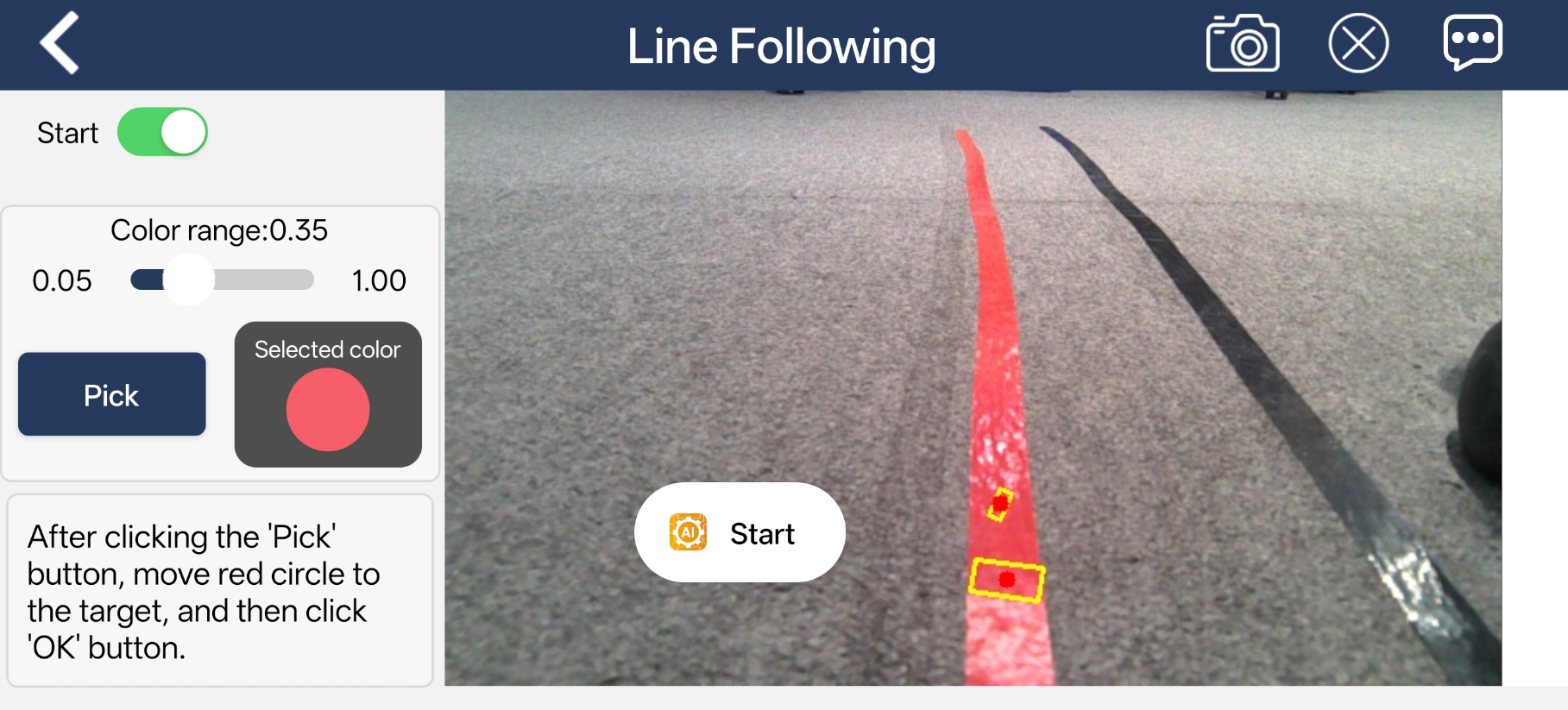
1.5.3.6 Line Following
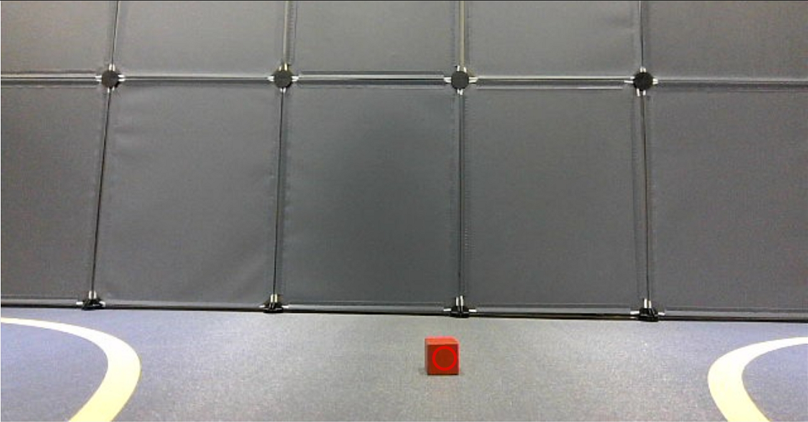
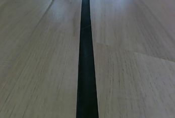
Note
Before starting this feature, lay out the tracking path with tape and place the robot on the track.
Choose an appropriate color range for target extraction. If the range is too wide, unwanted colors may be included. If the range is too narrow, the target may be lost. Also, avoid having objects with similar colors to the target in the camera’s view.
After the feature starts, please ensure there is no other object containing the recognition color except the target object within the camera view. Otherwise, the recognition result will be affected.
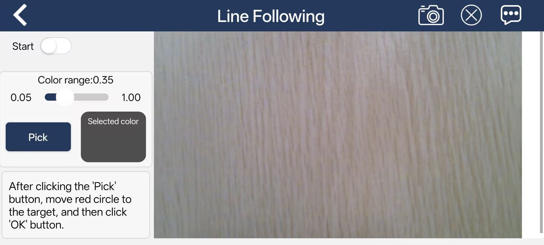
Interface Overview
Tap Line Following on the mode selection screen to enter the control interface.
This interface is divided into two sections:
The left panel contains the mode switch and color extraction tools.
In the right panel, display the live video feed from the camera.
Function
| Icon | Function Description |
|---|---|
|
Turn on/off the mode. |
| Adjust the color threshold range, with a value range of 0.05-1.00. | |
|
Extract the color from the specified area in the feed. |
|
After clicking the "Pick" button, it will switch to the "OK" button. Used to confirm the extracted color. |
|
Display the extracted color. |
 |
Display the current camera feed. |
Operating Steps and Effects
1. In this section, red tape is used as an example. After clicking the Pick button, drag the red circle in the live feed to the track to select its color.
2. Tap OK, and the selected color will be displayed in the Selected color area.
3. Tap Start to begin the feature, and the robot will follow the colored line automatically.
1.5.3.7 Driverless
Interface Overview
Tap Driverless on the mode selection screen to enter the control interface.
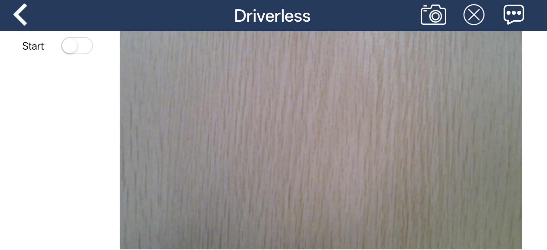
This interface is used for the autonomous driving feature. It is mainly divided into two sections:
The Start button on the left is used to activate the autonomous driving function.
The central area displays the live feed from the camera.
Function
| Icon | Function |
|---|---|
| Enable and disable the feature. | |
 |
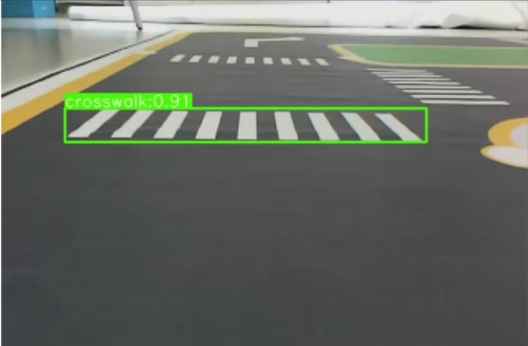
Display real-time detection results for traffic signs, lane markings, and traffic lights. |
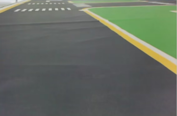
Operating Steps and Effects
Click the Start button to begin the autonomous driving feature. The robot will drive automatically along the center of the lane, slow down when approaching pedestrian crossings, respond to traffic signs accordingly, and follow traffic light signals, such as stopping at red lights and moving on green lights.
1.6 Wireless Controller Control
1.6.1 Notes
1. Before powering on the device, make sure the wireless controller receiver is properly inserted. This can be ignored if the receiver was pre-inserted at the factory.
2. Pay attention to battery polarity when placing the batteries.
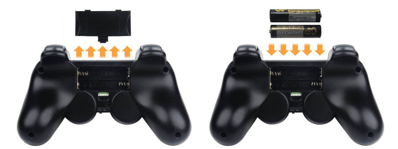
(1) Each time the robot is powered on, the app auto-start service will launch, which includes the wireless controller control service. If this service has not been closed, no additional actions are needed—simply connect and control.
(2) Since signals from wireless controllers can interfere with each other, it is recommended not to use this function when multiple robots are in the same area to avoid misconnection or unintended control.
(3) After turning on the wireless controller, if it does not connect to the robot within 30 seconds or remains unused for 5 minutes after connection, it will enter sleep mode automatically. To wake up the wireless controller and exit sleep mode, press the “START” button.
(4) If the robot does not respond while using the controller, try starting the relevant services. For detailed steps, refer to the document 2. Motion Control Course.
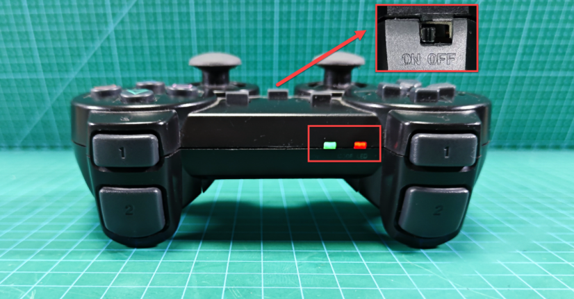
1.6.2 Device Connection
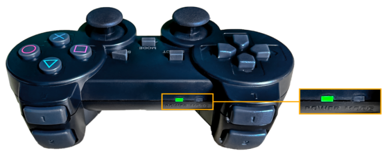
After the robot powers on, slide the wireless controller switch to the ON position. At this point, the red and green LED indicators on the wireless controller will start flashing simultaneously.
Wait a few seconds for the robot and wireless controller to pair automatically. Once pairing is successful, the green LED will remain solid while the red LED turns off.
1.7 Development Environment Setup
1.7.1 Remote Control Tool Introduction and Installation
1.7.1.1 Tool Introduction
There are two ways to remotely control the robot: graphical control and command-line control.
NoMachine and VNC are graphical remote-control softwares. After installation, you can connect to the robot’s hotspot and directly control the robot from your computer. The Jetson Nano, Jetson Orin Nano, and Jetson Orin NX controllers use NoMachine for connection, while the Raspberry Pi 5 controller uses VNC. When connected via the two softwares, you can clearly see the robot’s system desktop, making it convenient for intuitive operation.
In contrast to NoMachine and VNC, MobaXterm connects via SSH and focuses on command-line control. It does not display the robot’s full system desktop—only the command-line interface. For users who are familiar with terminal commands, this method allows faster robot control while reducing computational load and memory usage.
MobaXterm also comes with a lightweight X11 server, which enables graphical applications to be displayed directly when needed. Regardless of which controller you are using, MobaXterm’s SSH connection method is always supported.
In a word, NoMachine and VNC are best for scenarios requiring intuitive, visual operation, while MobaXterm is better suited for fast command execution. Choose the remote-control software according to your specific needs.
1.7.1.2 Nomachine Installation
Note
This tool is compatible with Jetson series controllers.
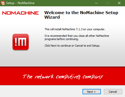
1. Navigate to the directory and double-click to open the folder 2. Softwares / 2. Remote Desktop Software / 1. Graphical Remote Desktop Access Tool, and then double-click to open the installation package nomachine_8.4.2_10_x64.
2. Click Next.
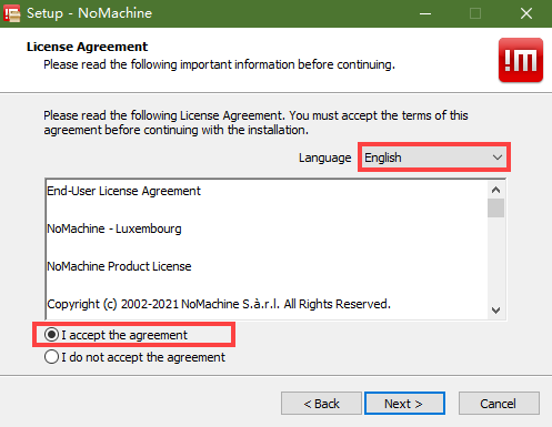
3. Select English as the installation language. Accept the license agreement by checking the box, then click Next.
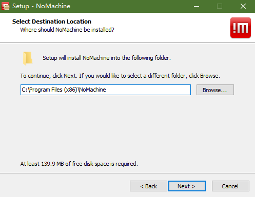
4. Keep the default installation path and click Next again.
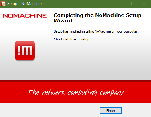
5. Wait for a moment, and the setup completion screen will appear. Click Finish to exit the installer.
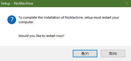
6. Click Yes to restart the computer. This step must not be skipped!
1.7.1.3 VNC Installation
Note
This tool is compatible with Raspberry Pi controllers.
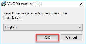
Locate the folder at: 2. Software \ 2. Remote Desktop Software \ 1. Graphical Remote Desktop Access Tool to install it. Double-click the file VNC-Viewer-6.17.731-Windows in this folder. In the pop-up dialog, select English as the installation language and click OK.
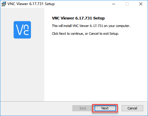
On the next screen, click Next.
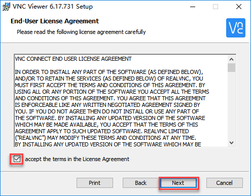
Agree to the license agreement, then click Next. Keep the default installation path, and click Next.
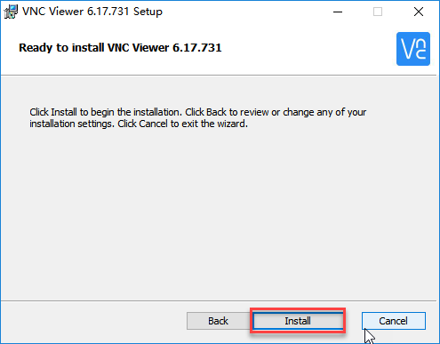
Click Install to begin installation.
Wait for the installation to complete, then click Finish to complete the setup.
After installation, launch VNC Viewer by clicking its desktop icon
 .
.
1.7.1.4 MobaXterm Installation
Note
This tool is compatible with any controller.
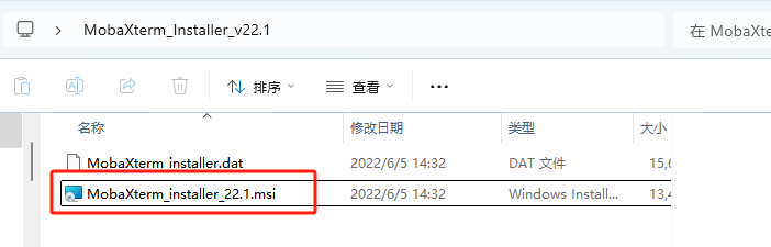
Locate the folder: 2. Software \ 2. Remote Desktop Software \ 2. SSH Remote Client, and open the installer and follow the prompts to complete the installation.
Click Next.
Accept the license agreement by checking the box, then click Next.
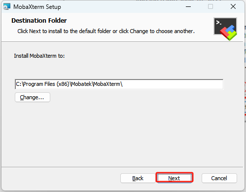
Keep the default installation path and click Next again.
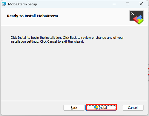
Click Install.
Wait for a moment, the setup completion screen will appear. Click Finish to exit the installer.
1.7.2 AP Mode Connection Steps
AP Mode (Direct Connection): The controller creates a hotspot that your phone and computer can connect to directly, but cannot access external networks.
Note
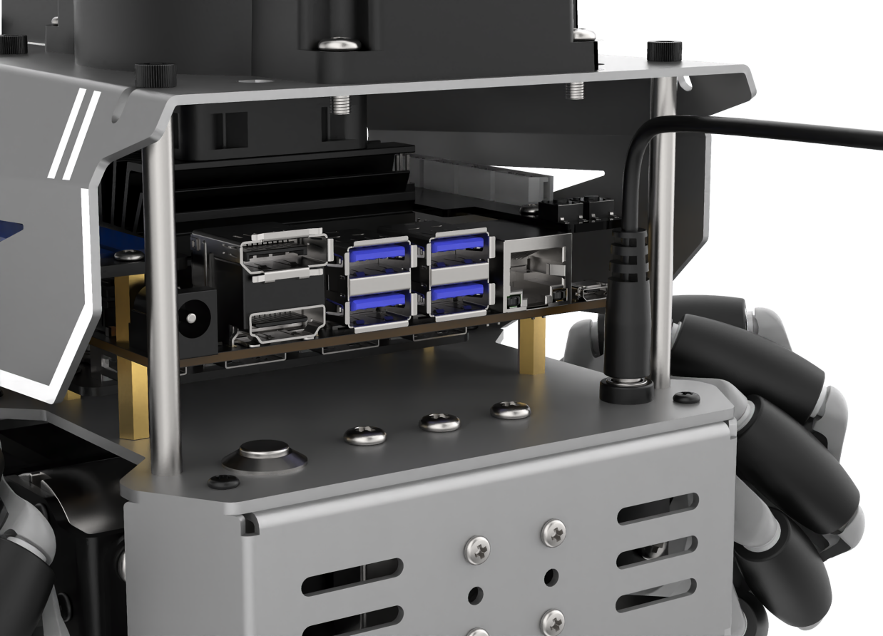
Before connecting the Jetson Orin Nano or Jetson Orin NX controller via NoMachine, ensure that a virtual display or an external monitor is connected. The connection location is shown in the diagram below at port 2.. This section provides only a general overview.
1.7.2.1 Connecting via NoMachine
AP Mode (Direct Connection): The controller creates a hotspot that your phone can connect to directly, but cannot access external networks.
1. The robot is set to AP mode by default. After powering it on, it will generate a Wi-Fi hotspot starting with HW. On your computer, search for and connect to the hotspot as shown in the figure by entering the password hiwonder.

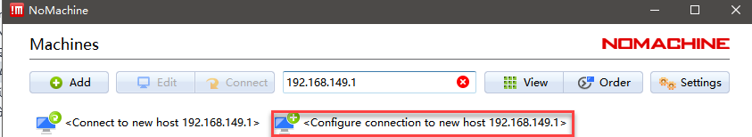
2. Open NoMachine and enter the IP address 192.168.149.1 in the search bar. Click Configure connection to new host 192.168.149.1.
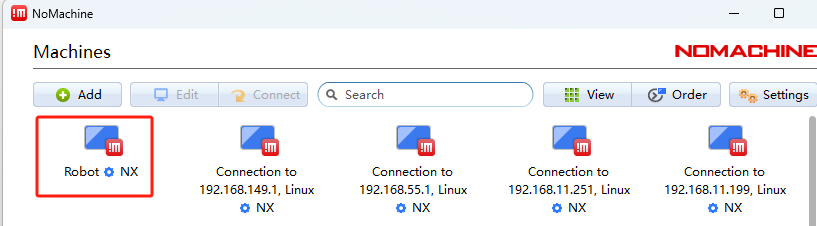
3. Once opened, change the Name field to Robot, leaving the other options unchanged, and click Add.
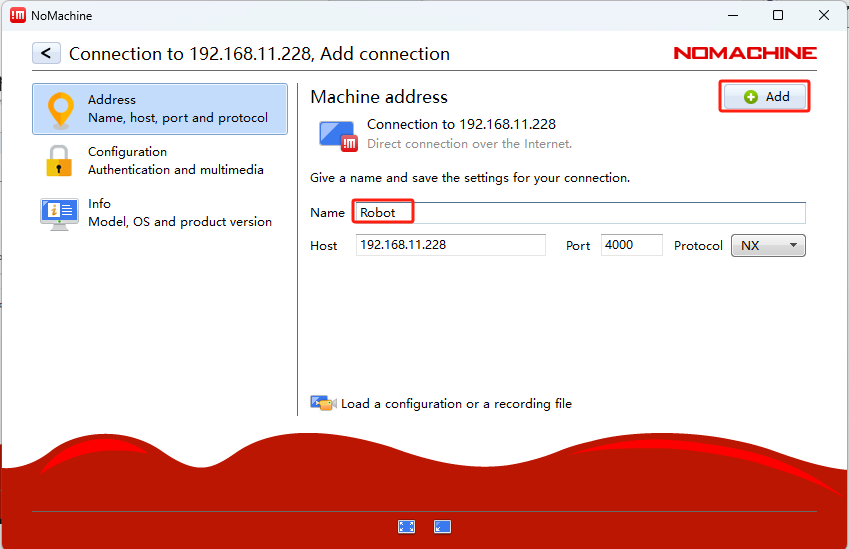
Then, double-click the entry named Robot.
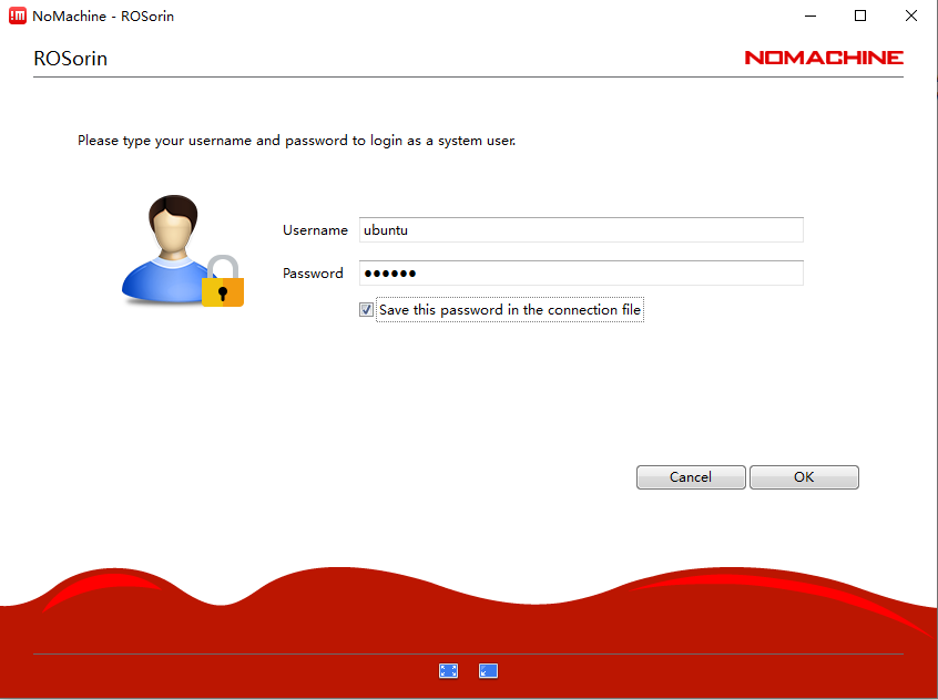
In the Username and Password fields, enter the following based on your controller:
For Jetson Nano, the default username is hiwonder and the password is hiwonder. For Jetson Orin Nano, the default username is ubuntu and the password is ubuntu. For Jetson Orin NX, the default username is ubuntu and the password is ubuntu. After entering the credentials, check the Remember password box and click the Login button. The following example uses the Jetson Orin Nano version:
Note
If the robot is configured in STA Mode, follow the same steps as above, but make sure to replace the IP address, Username, and Password in steps 2, 3, and 4 accordingly.
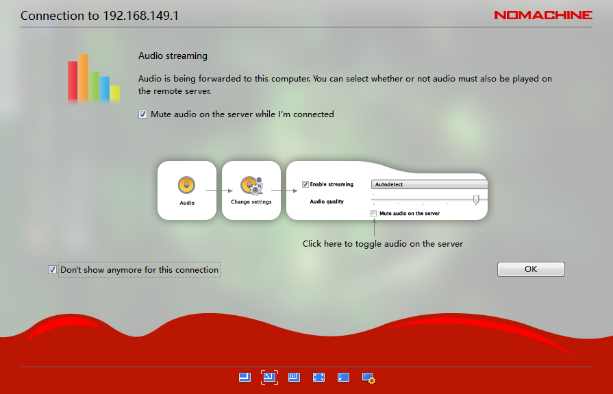
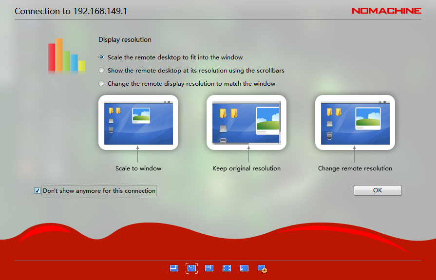
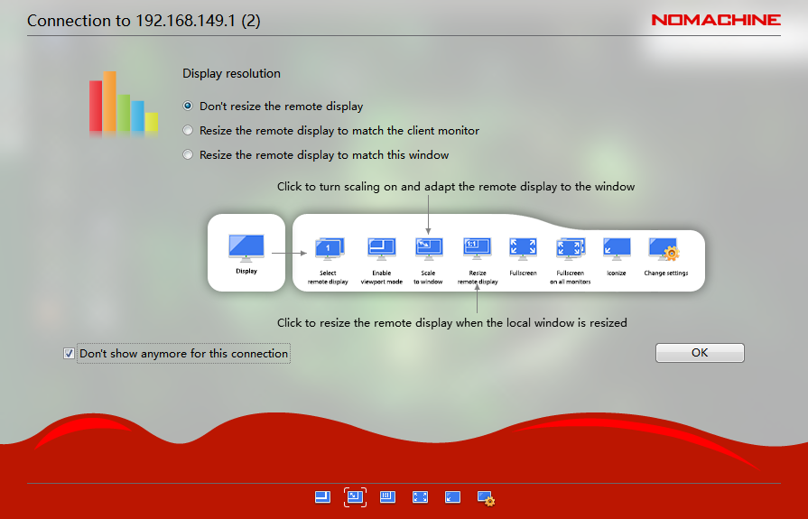
For configuration settings, select the appropriate checkboxes and click OK to proceed.
1.7.2.2 Connecting via VNC
Search for and connect to the hotspot starting with HW on your computer, as shown in the diagram below. The password for the connection is hiwonder.
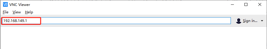
Open the VNC client and enter the IP address in AP mode: 192.168.149.1 in the address bar, then press Enter. If a warning about an unsecure connection appears, click Continue.
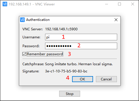
Wait for the login window to appear, then follow the steps in order: enter the username → enter the password → check Remember password → click OK.
Enter pi in the Username field, and enter raspberrypi in the Password field.
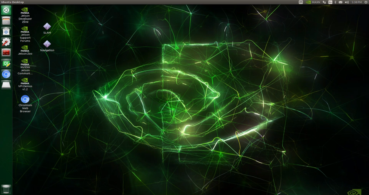
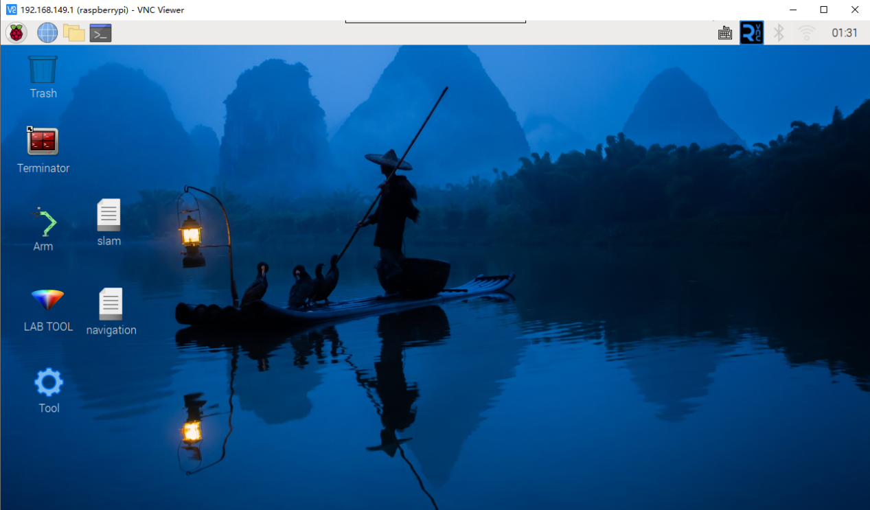
Once connected, the Raspberry Pi remote desktop will be displayed as shown below.
1.7.2.3 Connecting via MobaXterm
Taking the AP mode as an example, the same steps also apply to LAN mode, but you need to replace the IP address accordingly.
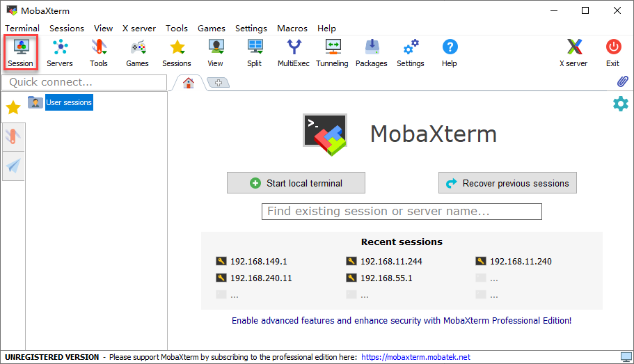
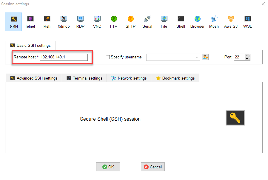
On the main interface, click Session in the upper-right corner to create a new session. In the session window, enter the robot’s recorded IP address 192.168.149.1 and then click OK.
Select SSH.
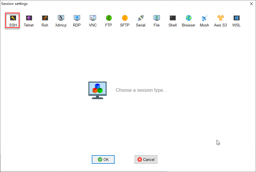
Enter the fixed IP address for AP mode: 192.168.149.1.
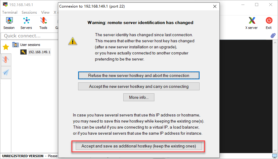
If a window like the one below appears, click the third option.
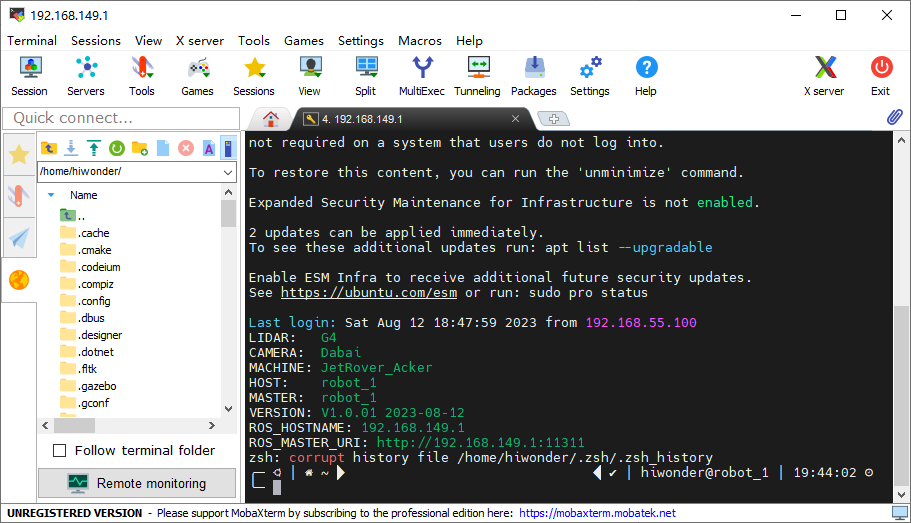
When prompted for the username and password, enter the credentials based on your controller version as shown below. The following example uses the Jetson Nano version:
For Jetson Nano, the default username is hiwonder and the password is hiwonder. For Jetson Orin Nano, the default username is ubuntu and the password is ubuntu. For Jetson Orin NX, the default username is ubuntu and the password is ubuntu. For Raspberry Pi 5, the default username is pi and the password is raspberrypi.

Note
The username must be entered in lowercase. Even if the account was originally created with uppercase letters, you must type it in lowercase when logging in.
After entering the username, press Enter to proceed to the password field.
When typing the password, no characters will be displayed. After finishing, press Enter again to log in.
If the password is correct, you will successfully access the system, and the interface will appear as shown below.
1.7.3 LAN Mode Connection
STA Mode (LAN Connection): The controller connects to a specified Wi-Fi network, and Internet access is available in this mode.
Note
If you want to configure the robot to use LAN Mode via your smartphone, make sure to enable the location service on your phone beforehand.
You cannot switch to LAN mode through the system’s default network settings, as shown in the figure below. Since the Wi-Fi has been specially configured, you will need to follow the network setup instructions provided later in this document.
After setting the robot to LAN mode, it will no longer broadcast a WiFi network starting with HW.
Configuration steps:
Click the terminal icon
 in the system desktop to open a command-line window.
Enter the following command and press Enter to go to the configuration directory.
cd wifi_manager
Then enter the following command and press Enter to open the configuration file:
vim wifi_conf.py
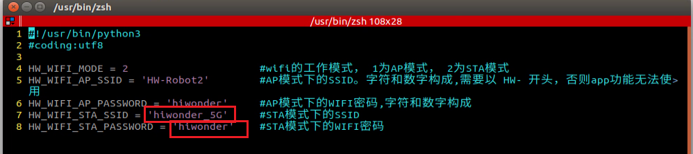
First, set the value of WIFI_MODE to 2. 1 stands for Direct Connection Mode, while 2 stands for LAN Mode.

Next, modify WIFI_STA_SSID and WIFI_STA_PASSWORD to the Wi-Fi name and password of your router. For example, hiwonder_5G is used here. Ensure that the WiFi name does not contain spaces.
Note
It’s recommended to use a 5G Wi-Fi signal for faster transmission. If you experience lag with a standard Wi-Fi connection, consider switching to a 5G network.
After confirming the input is correct, press ESC, then type
:wqto save and exit the file.

Restart the robot’s Wi-Fi service using the following command.
sudo systemctl restart wifi.service
Note
After restarting the robot’s Wi-Fi service, NoMachine will disconnect automatically. This happens because the device is in LAN mode, and connecting to a different Wi-Fi network causes the IP address to change.
To switch to Direct Connection Mode, simply edit the configuration file, comment out all the lines, save the changes, and restart the robot.
For instructions on finding the device’s IP address, refer to 1.5.2.2 LAN Mode Connection (Optional), then follow the steps in 1.7.2 AP Mode Connection Steps, updating the IP address with the one you’ve found.
1.7.4 Fixed IP Connection via USB Data Cable
Note
This section applies only to Jetson series controllers. It is not supported for the Raspberry Pi 5 controller.
The robot can achieve smoother remote operation by enabling the remote NDIS-compatible device and using a fixed IP address of 192.168.55.1. This method does not require connecting to the robot’s hotspot or Wi-Fi in LAN mode. The steps are as follows:
For the Jetson Nano controller, connect the robot to the computer using a Micro-USB data cable.
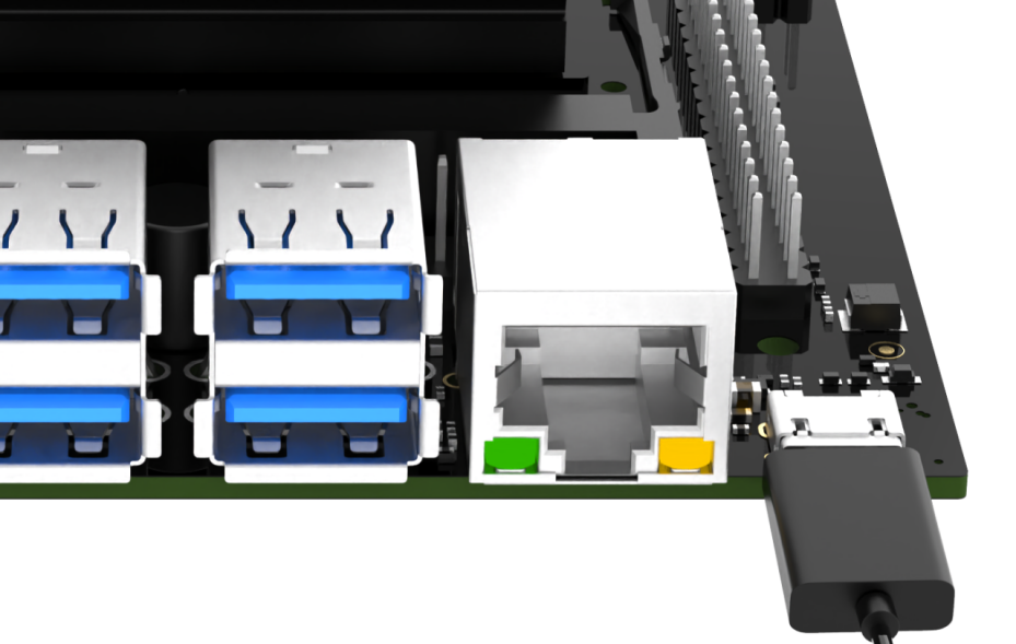
For the Jetson Orin Nano controller, connect the robot to the computer using a Type-C data cable.
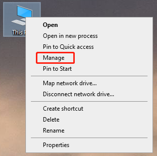
On the computer, right-click This PC on the desktop and select Manage.
Click Device Manager in the left panel, then find the NDIS driver under Network Adapters. Right-click the driver and select Update Driver.
Next, follow the steps in 1.7.2 AP Mode Connection Steps, and change the IP address field to 192.168.55.1.
1.7.5 Changing Chassis Type
Note
After replacing the chassis with a different type, the robot’s chassis type must be updated in the software.
The system is set to a Mecanum chassis by default. If using an Ackermann or differential chassis, the chassis type should be updated in the software first.
Steps:
1. Double-click the system desktop icon  to open the configuration tool.
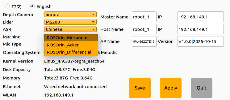
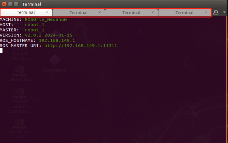
2. After the program loads, go to the Machine settings, where the current chassis type is ROSOrin_Mecanum.
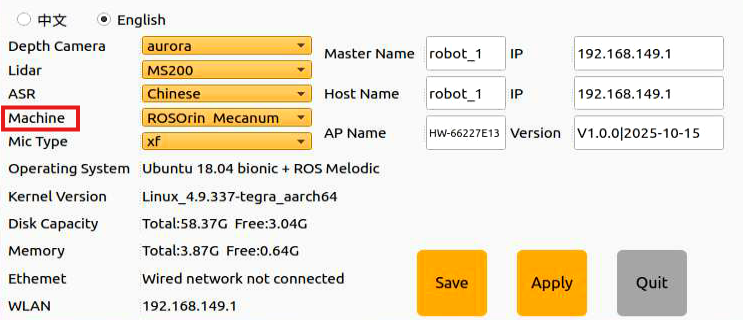
3. If using an Ackermann chassis, click the drop-down menu to switch to ROSorin_Acker. If using a four-wheel differential chassis, click to select ROSOrin_Differential.
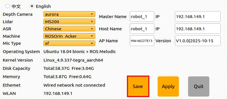
4. Click Save.
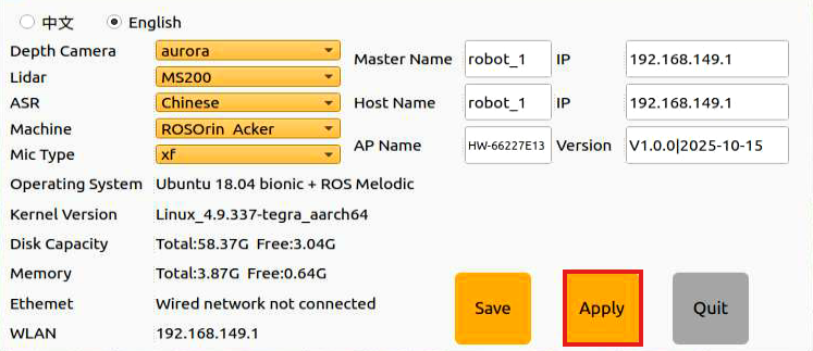
5. Click Apply and wait for the service to restart.
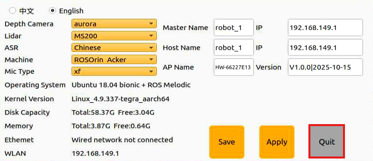
6. Finally, click Quit to close the software and complete the chassis change.
1.8 Manual Mapping
This section demonstrates how to quickly experience manual mapping. No complex operations are required, simply tap the corresponding icon on the touchscreen to begin.
Manual mapping requires controlling the robot using either a wireless controller or a keyboard. For a single-robot environment, using a controller is recommended for convenience. In a multi-robot environment, it is recommended to use a keyboard to avoid signal interference. Since signals from wireless controllers can interfere with each other, it is recommended not to use this function when multiple robots are in the same area, to avoid misconnection or unintended control.
After mapping is completed, the generated map will be saved. You can then enable the autonomous navigation feature to test navigation using the created map. Please note that the autonomous navigation feature will always use the most recently created map. Any newly created map will overwrite the previous map, regardless of the mapping method used.
1.8.1 Preparation
Before starting the robot, first ensure that the remote desktop tool has been installed according to section 1.7 Development Environment Setup, and that the connection to the robot has been established.
Next, confirm that the wireless controller’s receiver is properly connected to the robot’s USB port and securely plugged in.
1.8.2 Operation Steps
1.8.2.1 ROS1 Mapping
Note
This section is intended for the Jetson Nano controller.
This mode requires a pre-prepared enclosed space on a flat surface. If obstacles are placed, their height must exceed the Lidar’s horizontal level.
Place the robot in the prepared area, ensuring the space is spacious, flat, and enclosed to allow sufficient room for movement in all directions.
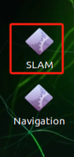
On the software desktop, select and open the SLAM icon for manual mapping.
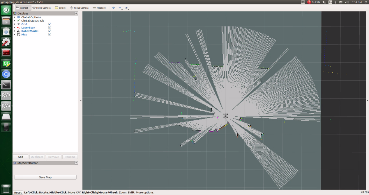
Multiple terminals will launch and run automatically, so it might take some time for the interface to fully load.
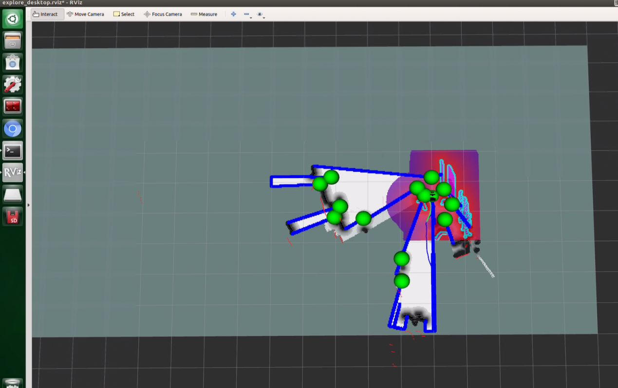
When the display interface appears, the system has started successfully.
You can now control the robot for mapping using the wireless controller. Function descriptions for each button are listed below:
Note
Keep the controller within a reasonable distance to avoid disconnection.
| Button/Joystick | Operation | Function |
| START | Press | Exit sleep mode |
| Left Joystick | Push forward/backward | Control robot's forward and backward movement |
| Push left/right | Control robot's left and right translation. Mecanum wheel chassis only. | |
| Right Joystick | Push left | Control robot's left turn |
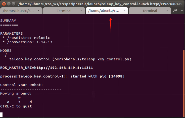
If using a keyboard for control, connect to the remote desktop and select a terminal that allows keyboard control.
The following table outlines the keyboard controls:
| Button | Function | Description |
|---|---|---|
| W | Move forward | Short-press to switch to the forward state, then the robot will keep moving forward. |
| S | Move backward | Short-press to switch to the backward state, then the robot will keep moving backward. |
| A | Turn left | Long-press to interrupt the forward or backward state and rotate counterclockwise in place. |
| D | Turn right | Long-press to interrupt the forward or backward state and rotate clockwise in place. |
When pressing W or S, the robot will continuously move forward or backward. When pressing A or D, the robot will interrupt the current forward or backward action and rotate in place. Releasing A or D will stop the rotation, and the robot will remain stationary.
Note
For the Mecanum wheel chassis, sideways movement is not supported when using keyboard control.
After movement is complete, tap the Save button in the lower-left corner to store the created map.
Once mapping is finished, the quick mapping function can be turned off by clicking the button
 in the upper-left corner of the interface.
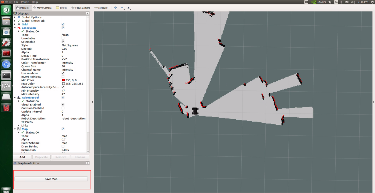
1.8.2.2 ROS2 Mapping
Note
This section applies to the Jetson Orin Nano, Jetson Orin NX, and Raspberry Pi 5 controllers.
This mode requires a pre-prepared enclosed space on a flat surface. If obstacles are placed, their height must exceed the Lidar’s horizontal level.
Place the robot in the area where mapping will take place.
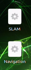
Tap the touchscreen, select and open the SLAM icon for manual mapping.
Multiple terminals will launch and run automatically, so it might take some time for the interface to fully load.

When the display interface appears, the system has started successfully.
You can now control the robot for mapping using the wireless controller. Function descriptions for each button are listed below:
Note
Keep the controller within a reasonable distance to avoid disconnection.
| Button/Joystick | Operation | Function |
| START | Press | Exit sleep mode |
| Left Joystick | Push forward/backward | Control robot's forward and backward movement |
| Push left/right | Control robot's left and right translation. Mecanum wheel chassis only. | |
| Right Joystick | Push left | Control robot's left turn |
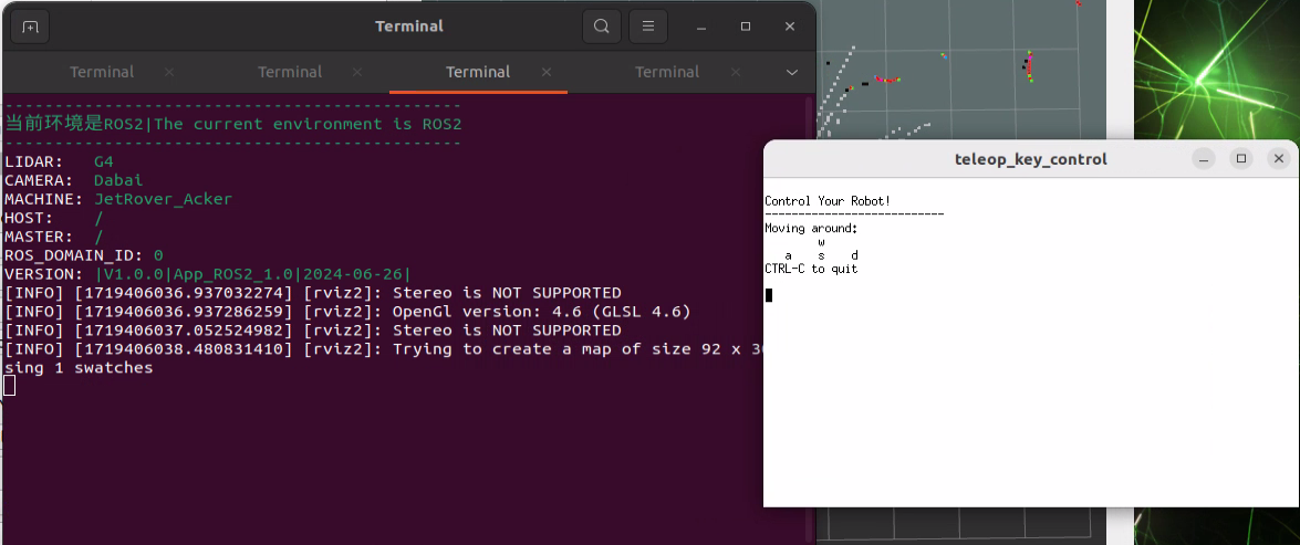
To use keyboard control, connect via the remote desktop and switch the terminal to keyboard control mode.
The following table outlines the keyboard controls:
| Button | Function | Description |
|---|---|---|
| W | Move forward | Short-press to switch to the forward state, then the robot will keep moving forward. |
| S | Move backward | Short-press to switch to the backward state, then the robot will keep moving backward. |
| A | Turn left | Long-press to interrupt the forward or backward state and rotate counterclockwise in place. |
| D | Turn right | Long-press to interrupt the forward or backward state and rotate clockwise in place. |
When pressing W or S, the robot will continuously move forward or backward. When pressing A or D, the robot will interrupt the current forward or backward action and rotate in place. Releasing A or D will stop the rotation, and the robot will remain stationary.
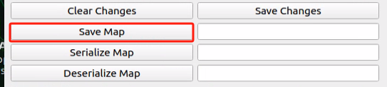
After movement is complete, press the Save Map button to store the created map.
Once mapping is finished, the quick mapping function can be turned off by clicking the Close button in the command line terminal.

1.9 Autonomous Mapping
Note
This section is intended for the Jetson Nano controller.
Enabling this function starts the robot’s movement immediately, so it must be placed on a flat surface beforehand.
This mode requires a pre-prepared enclosed space on a flat surface. If obstacles are placed, their height must exceed the Lidar’s horizontal level. The robot will stop automatically after completing autonomous mapping within the enclosed space.
Tap the touchscreen, then select and open the SLAM Automatic icon for autonomous mapping.
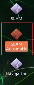
Opening it will automatically launch the program in the terminal. Once the interface appears, the setup is complete.
Then, the robot will start moving and mapping autonomously.
After completing autonomous mapping within the enclosed space, it will stop and automatically save the map.
1.10 Autonomous Navigation
Note
When starting navigation, the system will load the most recently saved map, whether it was created manually or through autonomous mapping. If both methods have been used, only the latest saved map will be kept.
1.10.1 ROS1 Autonomous Navigation
Note
This section is intended for the Jetson Nano controller.
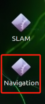
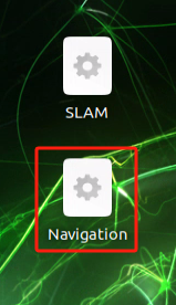
1. Power on the robot, then select the Navigation icon from the Quick Navigation menu.
2. A terminal will launch and run automatically, and it might take some time for the interface to fully load.
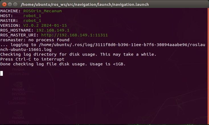
3. When the following interface appears, the setup is complete.
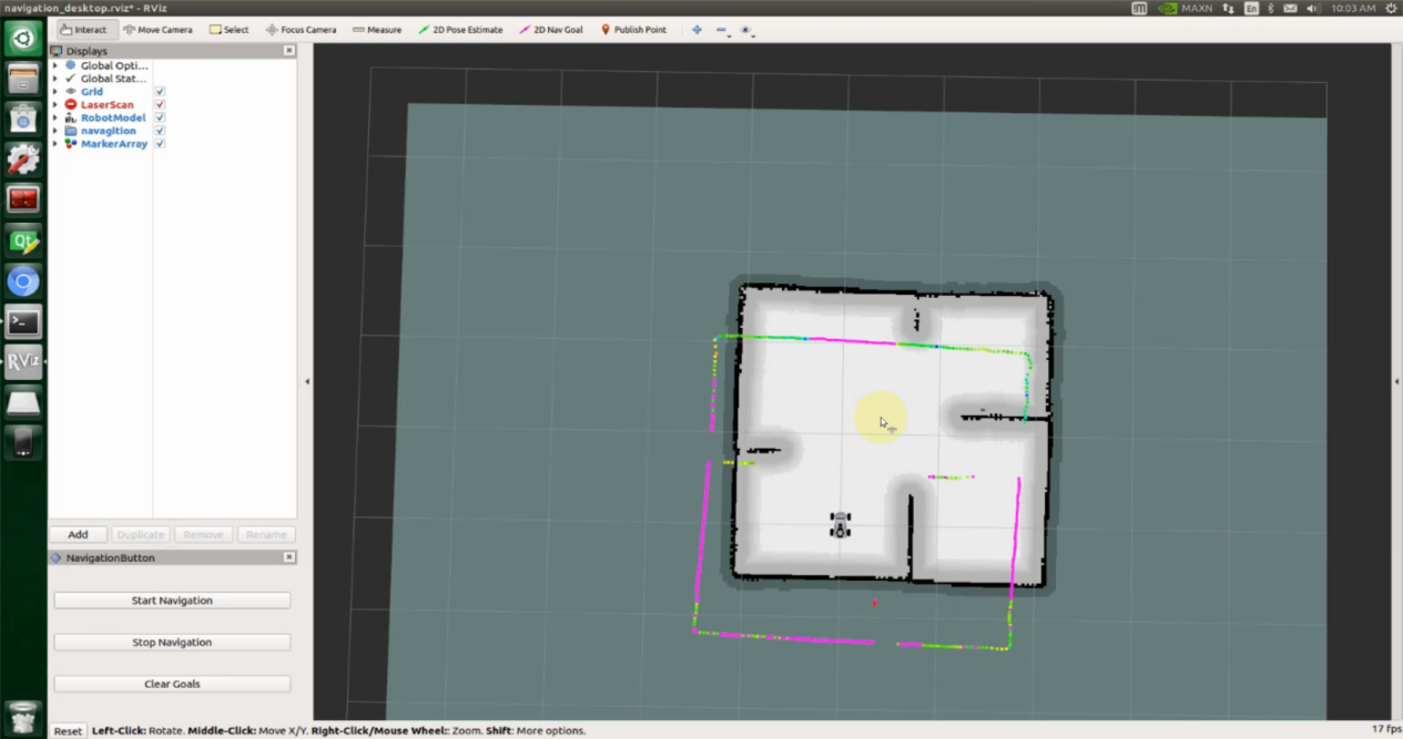
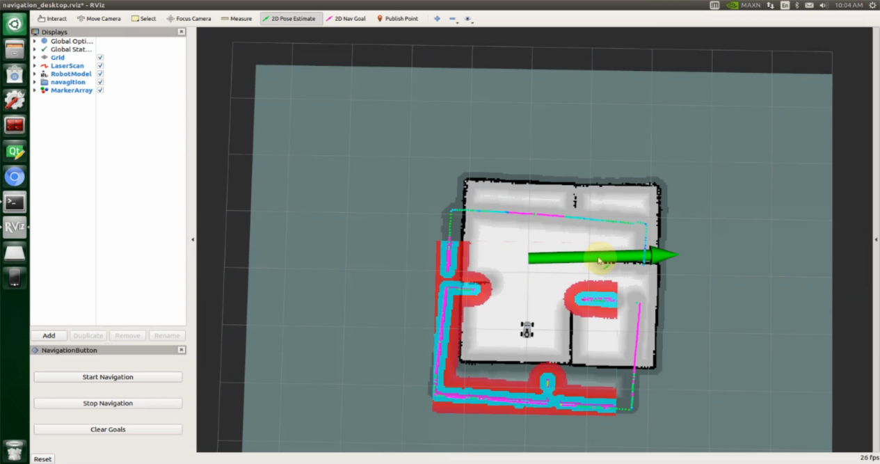
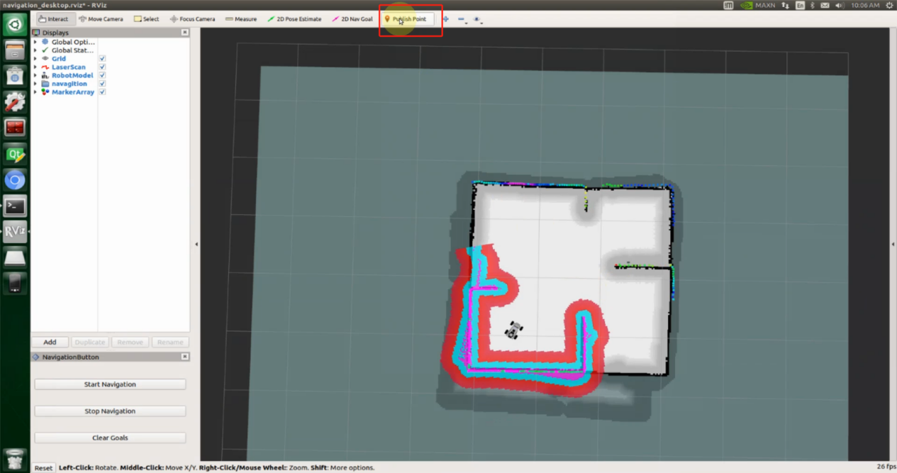
4. In the software menu bar, 2D Pose Estimate is used to set the robot’s initial position, 2D Nav Goal is used to set a single target point, and Publish Point is used to set multiple target points.
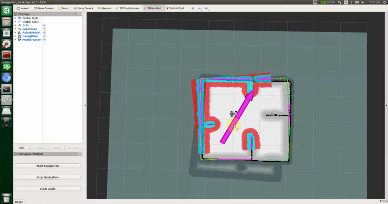
5. Click the icon  , then click on the map to set a target point. Press and drag with the mouse to adjust the robot’s orientation after reaching the target. Once selected, the robot will automatically generate a path and move to the target point.
Note
The icon changes the robot’s initial position in the map, while  sets the single-point navigation target.
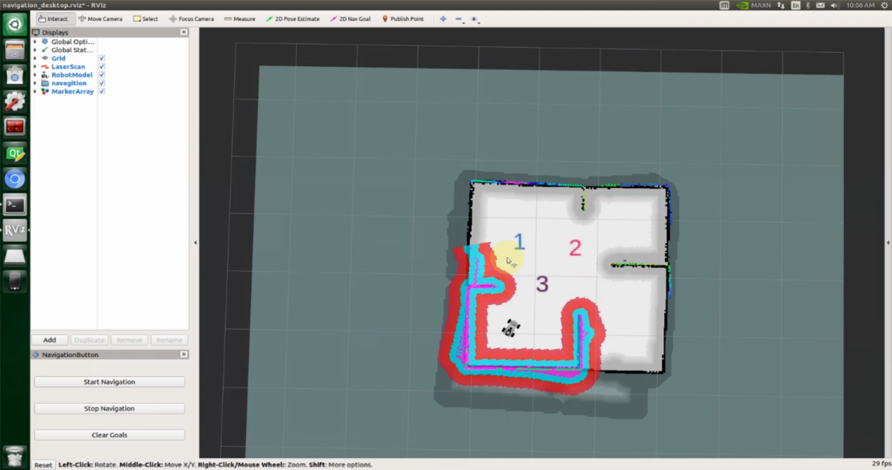
6. To set multiple navigation points, click the icon  and left-click on each point on the map in sequence.
Note
Click Publish Point before setting each target point.
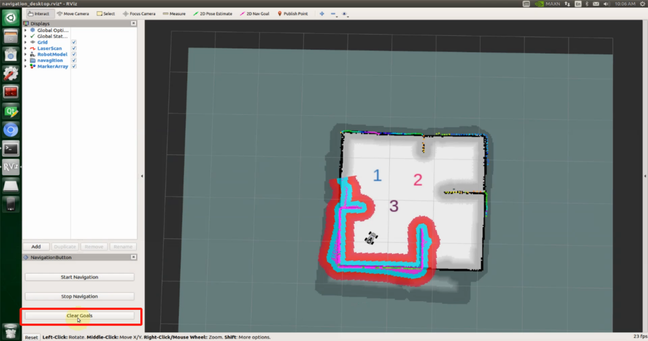
After all target points are set, click Start Navigation at the lower-left corner to begin navigation. During navigation, the robot will automatically avoid obstacles. To stop navigation, click Stop Navigation. The robot will stop after reaching the current target point.
Clicking Clear Goals will remove all set target points.
1.10.2 ROS2 Autonomous Navigation
Note
This section applies to the Jetson Orin Nano, Jetson Orin NX, and Raspberry Pi 5 controllers.
To begin, power on the robot, tap the touchscreen, and select the Navigation icon from the Quick Navigation menu.
A terminal window will open, and the program will start running and wait for the navigation interface to appear.
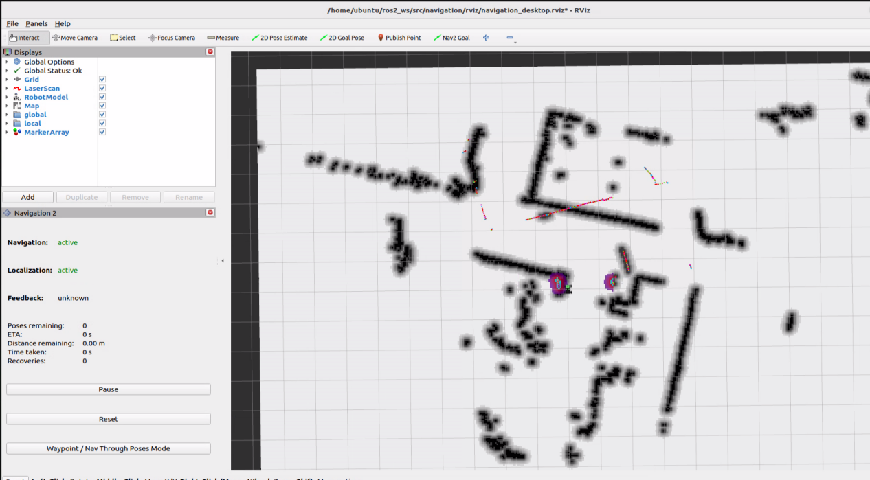
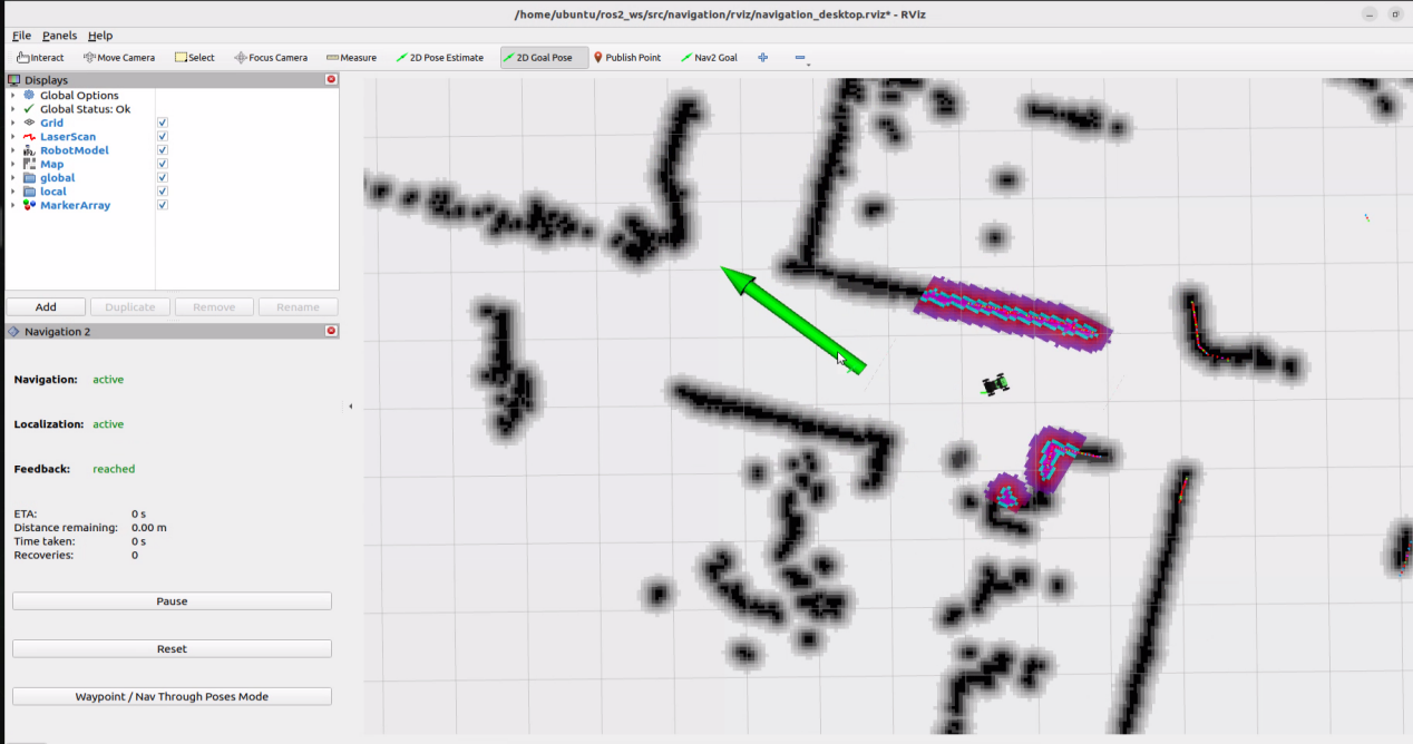
In the software menu, 2D Pose Estimate sets the robot’s initial position. 2D Goal Pose sets a single target point for the robot, suitable for basic navigation tasks without considering obstacle avoidance or path planning. Publish Point sets multiple target points for the robot. Nav2 Goal sets more complex navigation goals, such as specifying a target point, a target orientation, or a target area.

Click the icon
 to adjust the robot’s initial position on the map so it matches its actual location.
Click the icon
 , then click on the map to set a target point. If you click and drag, you can also define the robot’s orientation after it reaches the target.
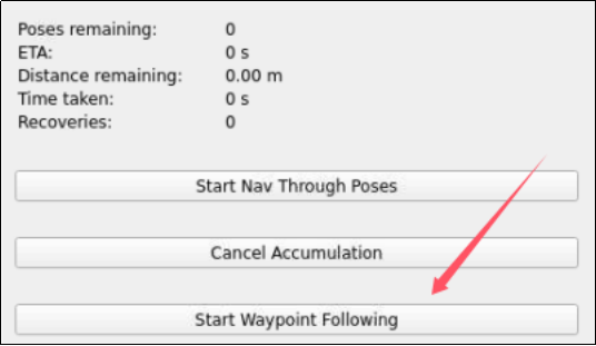
Click the lower-left icon
 to enable multi-point navigation. Then, click the icon
 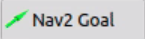 once for each target point you want to set. Click and drag to define the robot’s orientation at each point. Repeat this process to add multiple target points.
Note
Click the Nav2 Goal before setting each target point.
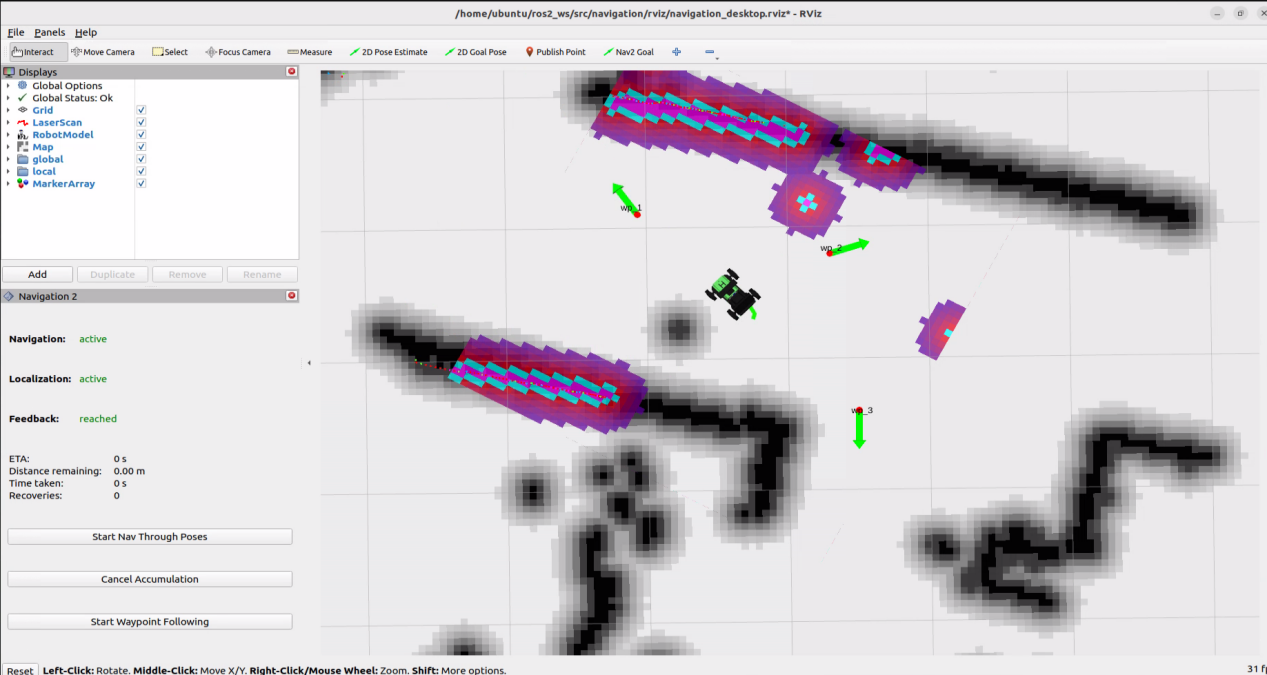
Once all target points are set, click Start Waypoint Following in the lower-left corner to begin. During navigation, the robot will automatically avoid obstacles along the way.
1.11 Hardware Introduction
This section introduces the robot’s hardware, including the electronic control system, ROS controller, LiDAR, depth camera, and other sensors.
1.11.1 Hardware System
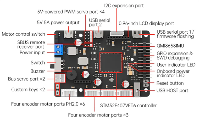
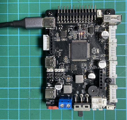
Diagram of the STM32 controller ports:
1.11.2 Electronic Control System
The robot’s electronic control system uses an STM32 controller as the low-level motion controller, connected to multiple DC geared motors with encoders. It also features a built-in IMU sensor with accelerometer and gyroscope, enabling chassis motion control and sensor data acquisition.
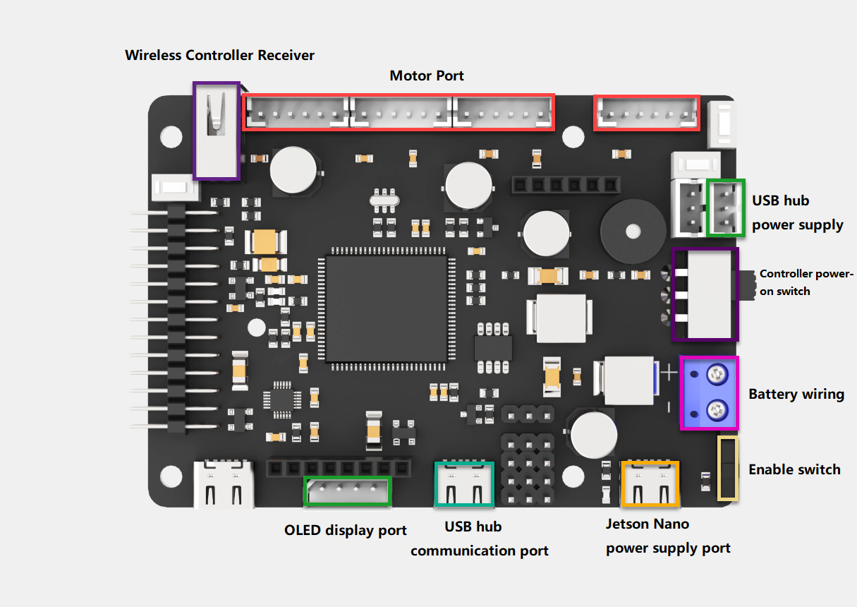
1.11.2.1 STM32 Controller
The STM32 robot motion controller is an open-source controller specifically designed for robotics development. It is compact and elegantly designed. A single board can control various chassis types, including Mecanum chassis, Ackerman chassis, differential drive, and Tank chassis.
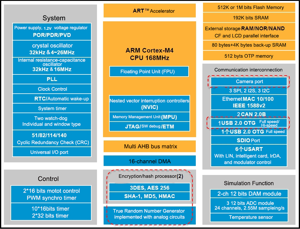
The controller uses the STM32F407VET6 as its main processor, based on the ARM Cortex-M4 core, running at 168 MHz, with 512 KB of on-chip Flash and 192 KB of SRAM, and it includes an FPU and DSP instructions. The system block diagram of the STM32F40x/41x series is shown below.
The controller features an onboard IMU with accelerometer and gyroscope sensors, supports up to four DC encoder motors, and includes two 5V power outputs with a maximum current of 5A. With abundant onboard resources and expansion interfaces, it is ideal for ROS robot development and can be paired with Jetson series ROS controllers to form a complete ROS robot system.
The front panel layout of the controller is shown in the figure below:

The controller provides the circuit schematic and features an SWD debug port. It supports USB serial programming for STM32 firmware updates and enables secondary development. On-board resources and peripheral example code are provided to facilitate learning and usage.
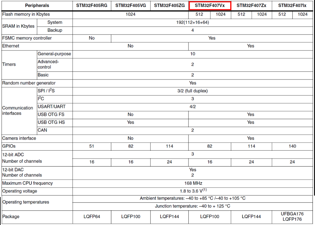
The onboard resources and peripherals of the STM32F407VET6 processor are shown in the figure below. For detailed information, please refer to the appendix documents in the folder STM32F407XX Data Sheet.
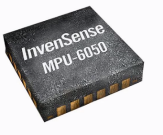
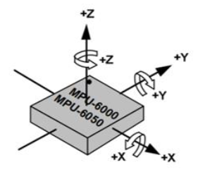
IMU Sensor
A 6-axis IMU sensor, the MPU6050, features a 3-axis accelerometer and a 3-axis gyroscope. It connects to the controller via the I2C port. The six axes of the IMU accelerometer and gyroscope are defined as shown in the figure below.
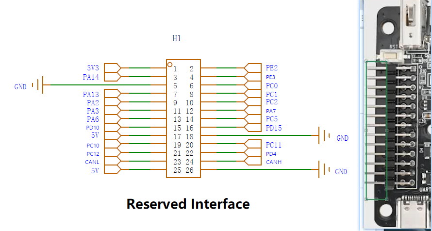
Reserved Ports
The reserved expansion ports provide connections for custom development.
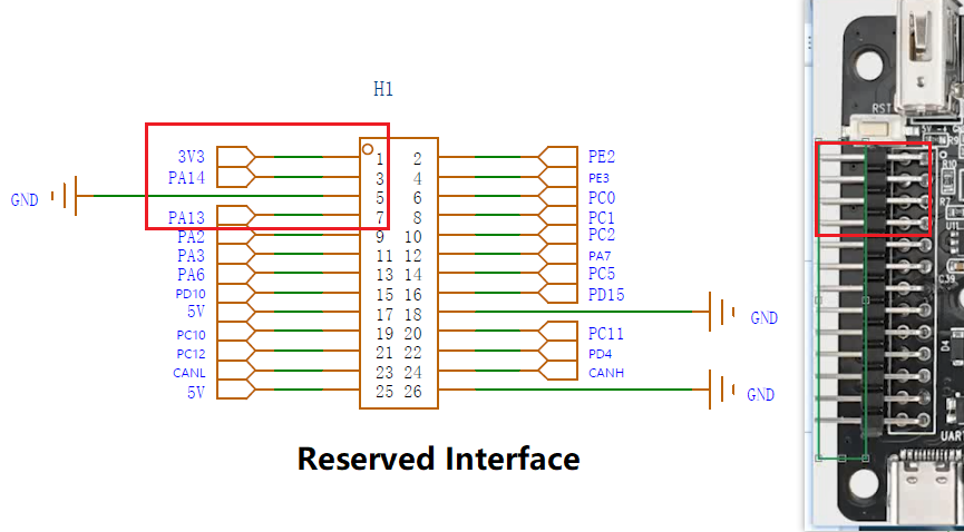
SWD Debug Port
The pins highlighted in red, 3V3, PA14, GND, PA13, serve as the SWD debug port, supporting SWD debugging.
PA14 serves as SWD_CLK and PA13 as SWD_DIO. Connect these pins to the corresponding port for debugging.
Power Supply Ports
The STM32 controller provides multiple external power ports, distributed as shown in the figure below.
For more detailed information, please refer to 4. Hardware Resources\1. STM32 Controller Files.
1.11.2.2 Power Supply
The robot uses a dedicated 11.1V 6000mAh lithium battery.
| Capacity | 11.1V 6000mAh | Charging Voltage | 12.6V |
| Discharge Current | ≤10A | Discharge Connector | SM Connector, Anti-reverse |
| Safety | Supports overcharge protection, overcurrent protection, overdischarge protection, and short circuit protection | ||
The robot should be charged using the provided dedicated charger. The red light on the charger indicates that it is charging, while the green light means the battery is either fully charged or not connected. Green light when no load, red light when charging, green light when fully charged.
Note
Do not charge the robot while it is powered on. Charging is only allowed when the robot is turned off.
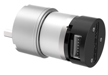
1.11.2.3 Hall Encoder DC Geared Motor
The Hall encoder is a speed-sensing module that uses a Hall-effect sensor, paired with a strong magnetic disk, and outputs pulse signals through AB-phase channels. The motor operates at 12V. The figure below shows the motor used in the robot and its pin configuration:
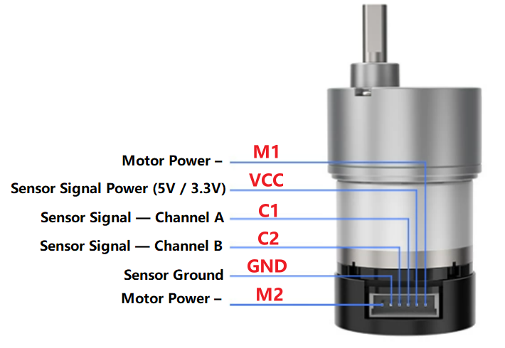
For more details:
1. The voltage between VCC and GND depends on the microcontroller supply, typically 3.3V or 5V.
2. The frequency of the square wave output on C1 and C2 depends on the motor speed and the number of pole pairs in the magnetic disk.
3. The voltage between M1 and M2 corresponds to the motor operating voltage.
The table below lists the specifications of the motors used in the robot:
| Rated Voltage | 12V | Gear Ratio | 1:90 |
| No-load Speed | 110rpm | Rated Speed | 85rpm |
| Stall Torque | 15kg.cm | Rated Torque | 2.6kg.cm |
| Stall Current | 3.2A | Rated Current | 0.36A |
| Rated Power | Approx. 8.3W | Encoder Type | AB Two-phase Encoder |
| Motor Type | Brushed Permanent Magnet | Output Shaft | 6mm D-shaped Eccentric Shaft |
| Encoder Voltage | 3.3~5V | Magnetic Ring Lines | 11 Lines |
| Interface Type | PH2.0-6PIN | Function | Built-in Pull-up Shaping, Single-chip |
1.11.2.4 PWM Servo
The Ackerman chassis of the ROSOrin robot uses a PWM servo to steer the two front wheels. The servo used is an LD-1501MG digital servo.
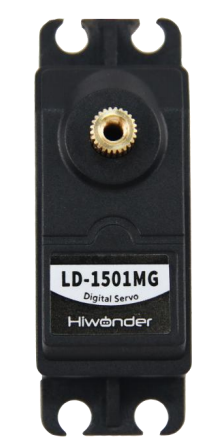
| Operating Voltage | DC 6-8.4V |
| No-load Current | 100mA |
| Stall Current | 2.4~3A |
| Control Method | PWM Pulse Width Control |
| PWM Pulse Width Range | 500~2500μs, corresponds to 0~180° |
| Pulse Period | 20ms |
| Rotation Speed | 0.16sec/60° (DC 7.4V) |
| Stall Torque | 13kg.cm (DC 6V), 15kg.cm (DC 6.5V), 17kg.cm (DC 7.4V) |
| Rotation Range | 0~180° |
| Servo Accuracy | 0.3° |
| Wire Length | 30cm |
| Gear Type | Metal Gears |
| Dimensions | 54.38mm × 20.04mm × 45.5mm |
| Weight | 61g |
| Applicable For | Various bionic robot joints and steering joints |
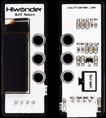
1.11.2.5 OLED Display Module
The OLED display module features a 0.91-inch blue OLED display, offering a wide viewing angle, fast response, stable graphics, high brightness, and high resolution. It is driven by the SSD1306 chip, which controls the content displayed on the OLED screen. The module also includes LEGO-compatible mounting holes, enabling a variety of creative DIY designs.
Specifications:
| Operating Voltage | DC 5V |
| Communication | I2C |
| PWR Indicator | Lights up after sensor power is supplied |
| Dimensions | 50mm × 20mm |
| 0.91-inch Blue OLED Screen Specifications | Resolution: 128 × 32 |
| Outline Dimensions (mm): 30.0 × 11.50 × 1.45 | |
| Display Area (mm): 22.384 × 5.584 | |
| Pixel Pitch (mm): 0.175 × 0.175 | |
| Pixel Size (mm): 0.159 × 0.159 | |
| Driver Chip: SSD1306 | |
| Module Structure: COG | |
| Modular installation, compatible with LEGO series | |
Port Description:
| Pin | Description |
|---|---|
| GND | Ground |
| 5V | Power Input |
| SDA | SDA Data Line |
| SCL | SCL Clock Line |
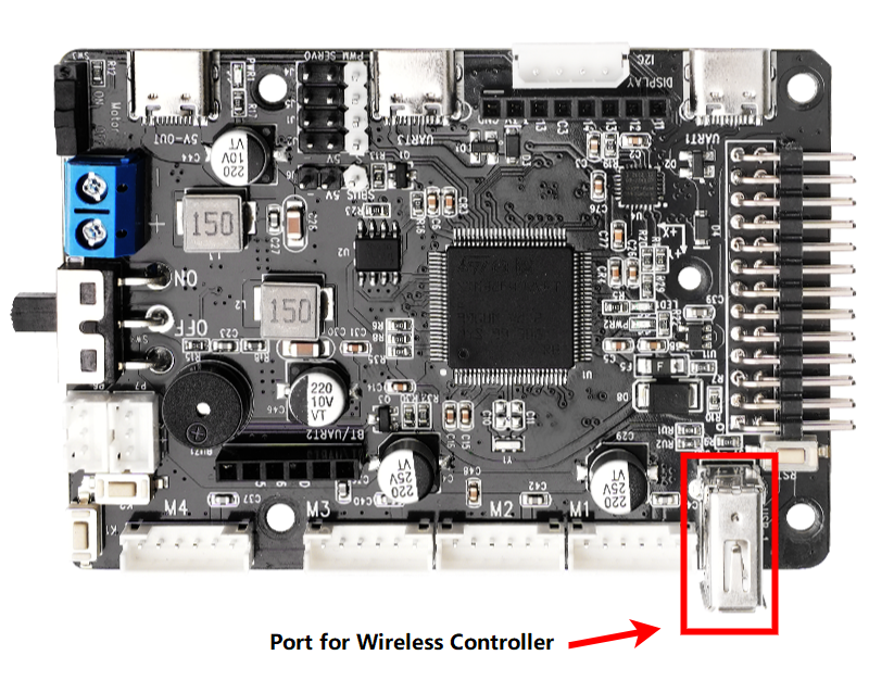
1.11.2.6 PS2 Wireless Controller
A USB receiver is connected to the chassis, enabling chassis movement control via a PS2 wireless controller.
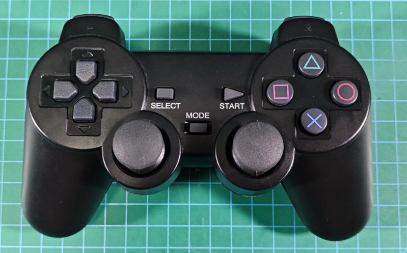
PS2 controller pinout and connection diagram to the controller:

Concept:
The USB receiver transmits differential signals through a pair of data lines, D+ and D-. When receiving the signals sent from the controller, it forwards them to the STM32, which then performs decoding.
STM32 Decoding: The STM32 reads the electrical signals on the data lines and converts them into binary data. Following the PS2 protocol, it decodes this data into specific commands.
The button mappings correspond to the table below.
| Button | Function | Description |
|---|---|---|
| START | Stop and reset chassis, wake up controller connection | Press START |
| Left Joystick Left | Move Forward | Hold |
| Left Joystick Right | Move Backward | Hold |
| Right Joystick Left | Turn left, while Mecanum chassis moves left. | Hold |
| Right Joystick Right | Turn right, while Mecanum chassis moves right. | Hold |
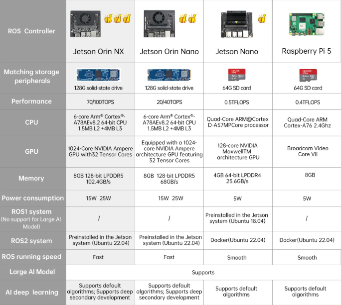
1.11.3 ROS Controller
The ROSOrin robot provides full support for ROS controllers. The operation is similar across different controllers. The Raspberry Pi 5 runs debian 12, while the Jetson series runs Ubuntu. The table below compares the specifications of Raspberry Pi 5, Jetson Nano, Jetson Orin Nano, and Jetson Orin NX controllers.
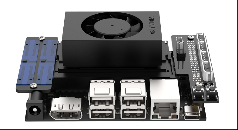
1.11.3.1 Jetson Nano
The robot uses a Jetson Nano as its ROS controller, consisting of a Jetson Nano core board and an expansion board. The core board is a compact yet powerful computer capable of running mainstream deep learning frameworks, providing sufficient computing power for most AI projects.
The expansion board exposes the LED indicators and control buttons, enabling network status to be monitored through LED signals and network modes to be switched from a mobile device. It also provides GPIO and I2C ports for hardware expansion.
The core board runs Ubuntu 18.04 with the ROS Melodic environment pre-installed, and a ROS 2 Humble environment configured within a Docker container.
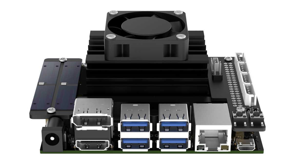
1.11.3.2 Jetson Orin Nano/Jetson Orin NX
The robot uses a Jetson Orin Nano as its ROS controller, consisting of a Jetson Orin Nano core board and an expansion board. The core board is a compact yet powerful computer capable of running mainstream deep learning frameworks, providing sufficient computing power for most AI projects.
The expansion board exposes the LED indicators and control buttons, enabling network status to be monitored through LED signals and network modes to be switched from a mobile device. It also provides GPIO and I2C ports for hardware expansion.
The core board runs Ubuntu 22.04 and comes preinstalled with the ROS 2 Humble environment.
1.11.3.3 Raspberry Pi 5
1.11.4 Deptrum Depth Camera
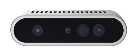
The robot is equipped with a Deptrum depth camera.
The Aurora930, part of the Deptrum® Aurora 930 series, uses 3D structured light technology to capture the three-dimensional structure of objects and spaces. Fusing RGB images from the color camera with depth data, it provides efficient and convenient 3D perception capabilities.
Its specifications are shown in the diagram and table below.
| Module Parameters | Overall Size | 76.5 × 20.7 × 21.8 mm |
| Baseline | 40 mm | |
| Interface | USB 2.0 Wafer Socket | |
| Depth Accuracy | 8mm@1m | |
| Depth Precision | 3mm@0.5m, 7mm@1m | |
| Working Distance | 15~300cm | |
| Operating Temperature | -10°C~55°C | |
| Operating Humidity | 0%~95%, Non-condensing | |
| Ambient Light | 3~80000Lux | |
| Power Supply | 5V±10%, 1.5A | |
| Power Consumption | Total Avg<1.6W | |
| Safety | Class 1 Laser Safety | |
| Image Performance | Depth Data Format | Raw 16 |
| Depth Resolution/Frame Rate | 640×400/12fps/ 74°×51° | |
| Color Data Format | NV12 | |
| Color Resolution/Frame Rate | 640×400/12fps/ 74°×51° | |
| Infrared Data Format | Raw 8 | |
| Infrared Resolution/Frame Rate | 640×400/12fps/ 74°×51° | |
| Firmware Capabilities | Firmware Upgrade | Supports USB Online Upgrade |
| Warm Start Delay | <300ms | |
| System Compatibility | Compatibility | Linux \ ARMv8 \ ROS \ Windows |
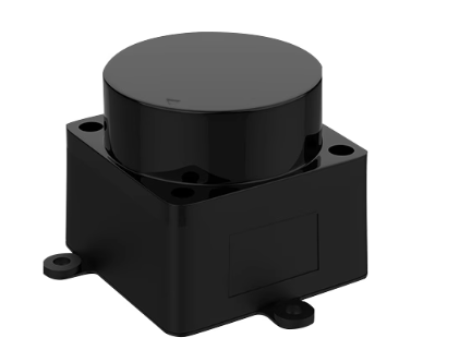
1.11.5 LiDAR
LiDAR is a sensor that uses laser beams to obtain precise positional information. It has a wide range of applications in robotics, including obstacle avoidance, object following, SLAM mapping, and navigation.
The robot is equipped with the MS200 LiDAR.
| Lidar Model | Aurida MS200 | Measurement Principle | TOF Distance Measurement |
| Recommended Scenarios | Indoor and Outdoor Applications | Supply Voltage | 5V |
| Scanning Range | 360° | Measurement Radius | Black Object: 12m |
| Communication Rate | 230400bps | Sampling Frequency | 4500 times/s |
| Scanning Frequency | 7~15Hz, Default 10Hz | Angular Resolution | 0.4° @5Hz 0.8°@10Hz |
| Supply Current | Typical 260mA | Output Interface | Standard Asynchronous Serial (UART) |
| Operating Temperature | -10°~ 50° | Distance Accuracy | ≤ 4mm [0.1 m~2m) ≤ 15mm [2m~12m] |
| Product Size | 37.7 × 37.5 × 32.5 mm |
Wiring Instructions:
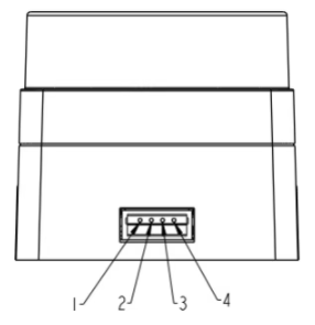
| Pin | Signal | Attribute | Description |
|---|---|---|---|
| 1 | Tx | Serial Data Transmit | Tx (Device Transmit, 0V~3.3V) |
| 2 | Rx | Serial Data Receive | Rx (Device Receive, 0V~3.3V) |
| 3 | GND | Power Input Negative | GND (0V) |
| 4 | VCC | Power Input Positive | DC5V (4.5V~5.5V) |
1.11.6 Microphone Array Module
This is an optional hardware module that enables voice wake-up and voice control functions on the robot. For related tutorials, please refer to the document 8. Voice Interaction Applications.
The robot is equipped with an R818 noise reduction board and a circular six-microphone array. The microphones are arranged in a planar layout to capture and process the spatial characteristics of the sound field. The system supports sound source localization, background noise suppression, interference and echo reduction, enabling 360° effective audio capture.
R818 Noise Reduction Board:
The R818 board is a multi-microphone voice front-end solution. It features a quad-core high-performance edge computing processor. Integrated with iFLYTEK’s voice algorithms, it utilizes the microphone array’s spatial filtering capability to locate the speaker, form a directional pickup beam, and suppress off-axis noise, achieving clearer and more accurate far-field voice capture. For human-robot interaction devices, it also includes a high-performance echo cancellation algorithm, reducing the difficulty in speech and semantic recognition. This allows developers to quickly integrate features such as multi-microphone audio capture, wake-up, noise reduction, and echo cancellation.
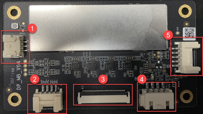
| Port No. | Port Name | Description |
|---|---|---|
| 1 | Serial Port | Can be used for PC communication |
| 2 | Reference Signal Port | Amplifier / Echo Cancellation Reference Signal |
| 3 | Microphone Port | Connects a 6-channel microphone array |
| 4 | Independent Power Port | Power input port |
| 5 | UAC Port | Audio output port |
1.12. ROS Introduction
The ROS robot’s core system consists of two main parts. The first is chassis control, driven by the STM32 controller, responsible for robot motion control and sensor data acquisition. The second is ROS control, centered on the ROS main controller, which runs the ROS system and associated functional algorithms.
1.12.1 ROS Controller Hardware Connection
The standard connection setup requires a power cable and a USB serial cable. Communication between the STM32 controller and the ROS controller is established via the onboard USB serial interface. The ROS controller can be powered directly through the STM32’s power output port. The connection diagram is shown below:
1.12.2 ROS Serial Communication Overview
Serial communication is one of the most common input and output methods in microcontroller development and robotic systems. In this robot, data exchange between the Jetson Nano and the STM32 controller is carried out via a serial interface.
To ensure smooth communication between software tools and hardware devices, a standardized RRC protocol based on hexadecimal data transmission is adopted. This protocol serves as the foundation for communication and programming between the upper and lower controllers in this and subsequent products.
For detailed information on the communication protocol and its parsing, refer to the document RRC Communication Protocol with the Host Computer located under 4. Hardware Materials \ 1 STM32 Controller Resources.
1.13 STM32 Source Code
1.13.1 Introduction
The STM32 controller serves as the robot’s underlying motion control unit. It comes pre-flashed with the corresponding firmware at the factory and is ready for immediate use. For most ROS development purposes, updating the STM32 firmware is not necessary. However, users who wish to perform low-level STM32 development can update or debug the STM32 code as needed.
The STM32 controller supports ISP updates via the USB serial interface and can also be updated or debugged through the SWD interface. As the robot’s low-level driver board, the STM32 is responsible for motor PID control, encoder and IMU data acquisition, RGB control, and supports multiple control methods, including PS2 wireless controller, app via Bluetooth, and RC transmitter. It communicates with the ROS-based chassis driver node via serial interface, receiving target velocity vectors from the ROS core and sending back real-time speed calculated from odometry, IMU data, and battery voltage information. To better support these functions, the STM32 runs software built on the FreeRTOS embedded operating system.
The STM32 source code for the STM32 controller can be found in the folder 3. Source Code / STM32. For a detailed explanation of the implementation principles and code analysis, refer to 4. Hardware Materials \ 1 STM32 Controller Resources.
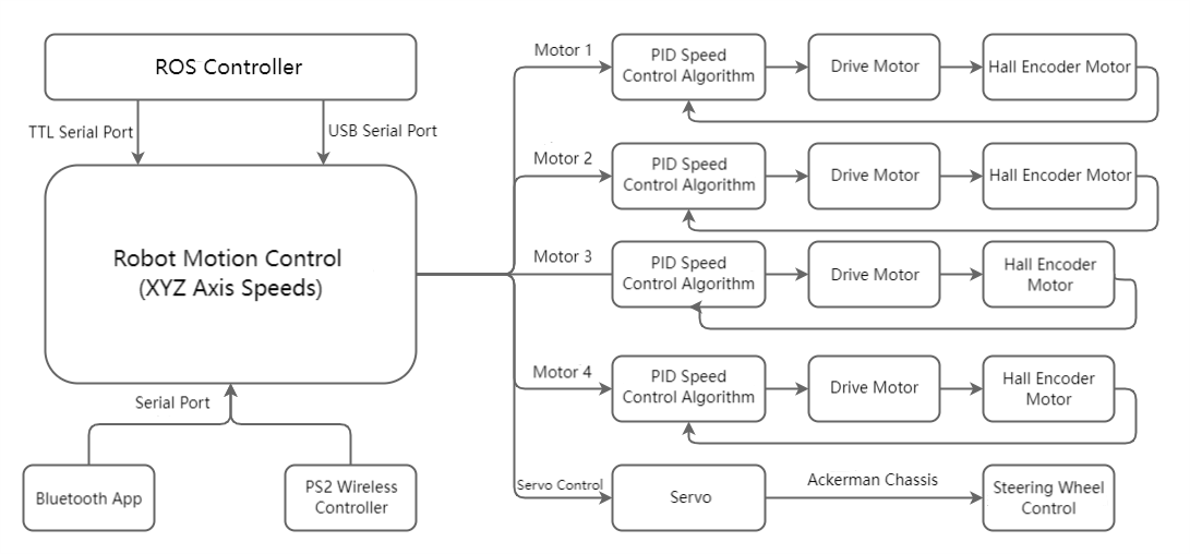
1.13.2 Control Process
The robot supports multiple control methods, all based on adjusting the robot’s target velocity. The target velocity is processed through inverse kinematics to calculate the desired motor speeds, which serve as inputs to the motor PID controllers. After PID computation, PWM control signals are output via the STM32 timers to the motor drivers. The motor drivers then control the motor rotation, while encoders collect the real-time motor speed and feed it back to the PID controllers, forming a closed-loop speed control system. The STM32 motor control flow for the robot is shown below.
Note
Motor requirements vary by robot type: Mecanum and four-wheel differential robots require four motors, while Ackerman robots require two motors, with the front wheels steered by servos.
1.13.3 Program Framework
The underlying source code is developed on FreeRTOS. Unlike interrupt-driven control, FreeRTOS executes tasks in a scheduled, time-shared manner, whereas interrupts typically have a higher priority than any task. Robot task allocation is as follows:
Robot_Task: Responsible for robot control, kinematics processing, IMU data acquisition, and data transmission, as well as miscellaneous management tasks. This includes low-frequency operations such as battery monitoring, IMU calibration, and buzzer alerts.
1.13.4 Program Analysis
For a more detailed explanation of the STM32 code, refer directly to the source files, which contain comprehensive comments. The source files are located in the tutorial package under STM32 Controller Resources.
1.13.5 Kinematics Models
The software supports multiple robot chassis types, each with distinct characteristics.
Mecanum wheels enable full 360° omnidirectional movement, allowing the robot not only to move forward and turn but also to translate in any planar direction.
Ackerman chassis operates like a car, with front-wheel steering controlled by servos.
For detailed explanations of the kinematics models for each chassis type, refer to the document tutorials under 2. Chassis Motion Control Course.
1.13.6 Project Compilation
Once the program is written, it must be compiled into machine code to run on the embedded system. Keil5 provides a built-in compiler to convert the source code into an executable file.
The compiler generates target files based on the processor architecture and instruction set. Additionally, the compiler can optimize the code to produce a more efficient and stable executable. The compilation process is as follows:
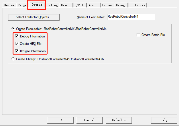
Enable the option to generate a hex file:
(1) In the menu bar, click Project, then select Options for File ‘app.c’.
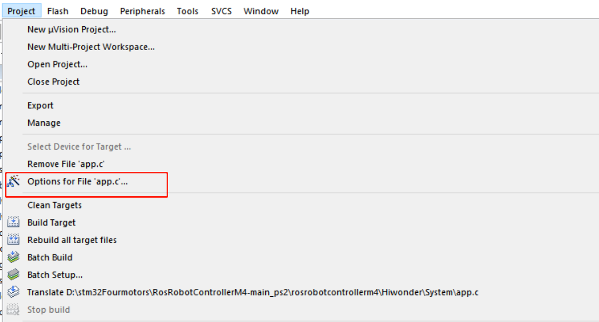
(2) Click the Output tab, check the three options shown in red, and click OK.
(3) In the menu bar, click Project and select Build Target from the dropdown to compile the project.
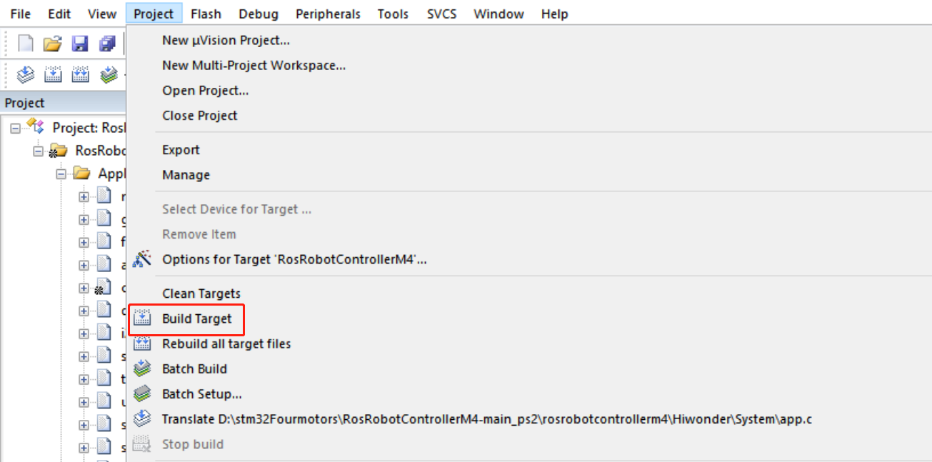
(4) Alternatively, click the build icon on the toolbar to start compilation.

(5) Once compilation completes successfully, the Build Output window at the bottom of the interface will display a success message.
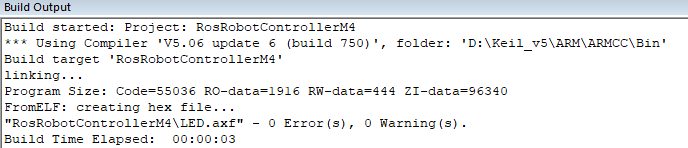
Note
If the Build Output window shows Error(s) after compilation, double-click the error to jump to the corresponding line, fix the issue, and recompile. Warning(s) can be ignored.
1.13.7 Program Download via USB
After compiling the project, the generated hex file can be flashed to the STM32 controller. The following hardware and software are required for this process.
Hardware and Software Requirements
Software: FlyMcu, located in 2. Softwares \ 4. USB Serial Download \ FlyMcu.

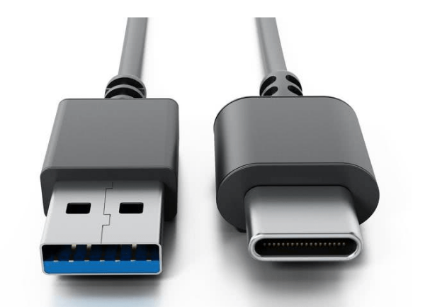
Hardware: Type-C cable and STM32 controller.
1. Use a Type-C cable to connect your computer to the STM32 controller.
Programming Steps
The following steps illustrate the procedure, using the program RosRobotControllerM4-ros as an example:
(1) Hardware Connection
Connect the Type-C cable to the STM32 controller’s Type-C port (UART1) and the computer’s USB port: UART1
(2)Basic Configuration
Open the FlyMcu software, click EnumPort in the top menu, select the correct port, and set the baud rate (bps) to 115200:

In the software interface, click the STM ISP option and configure it as shown below:
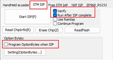
At the bottom of the interface, select Reset@DTR Low(<-3V), ISP@RTS High.

(3) Firmware Download
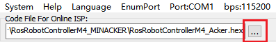
In FlyMcu, click the button in the red frame to select the hex file to flash.
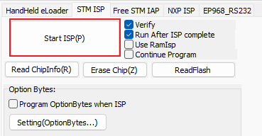
Return to the previous interface and click the Start ISP (P) button to begin flashing the selected hex file to the STM32 controller.
The process is flashing.
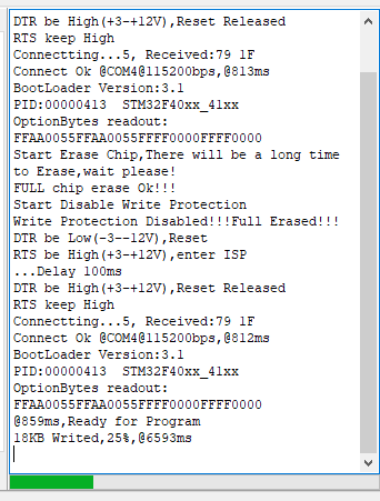
Once complete, a confirmation message will appear in the sidebar as shown in the image.
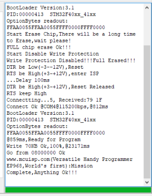
Note
The STM32 controller comes preloaded with the factory program for communication with the Jetson Nano controller and associated sensor modules. This program can be reflashed using the RosRobotControllerM4.hex file.
1.14 System Software Architecture
1.14.1 Introduction to ROS1 File Directory
Note
This section is intended for the Jetson Nano controller.
Click ![]() to open the command terminal, enter the command ls, and press Enter to list the files in the home directory:
to open the command terminal, enter the command ls, and press Enter to list the files in the home directory:
ls
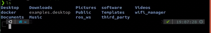
Folder descriptions:.
| Directory Name | Function |
|---|---|
| wifi-manager | Wi-Fi management tool |
| software | Directory for installed software |
| ros_ws | Workspace containing all feature functionalities |
| Third_party | Directory for additional ROS2 packages, such as trained YOLOv8 models |
| Music | Music files |
| Pictures | Directory storing images |
| Public | User-defined folder |
| Templates | User-defined template folder |
| Videos | Video storage |
Enter the command cd ros_ws/ and press Enter to access the robot workspace directory, then type ls to list the files and folders inside.
cd ros_ws/
ls
Folder descriptions:.
| Directory/File Name | Description |
|---|---|
| build | Build space which stores cache files generated during compilation |
| command | Contains command files for implementing various functions, making them easy to locate. |
| devel | Contains compiled target files and executables |
| logs | Folder for storing log files |
| src | Source code folder for function packages |
Enter the command cd ros_ws/src and press Enter to access the robot workspace directory, then type ls to list the files and folders inside.
cd ros_ws/src
ls
Folder descriptions:.
| Directory Name | Type Description | Function |
|---|---|---|
| app | App feature directory | Gesture control, Lidar, line tracking, etc. |
| interfaces | Communication interface files | ROS message and service communication files |
| slam | Mapping features | Map generation and saving |
| bringup | System services | Launches the app, wireless controller control, etc. |
| multi | Multi-robot features | Includes multi-robot mapping, multi-robot navigation, and more |
| third_party | Third-party package directory | Includes ROS packages for AprilTag, LiDAR, depth cameras, and more |
| calibration | Calibration parameters | IMU, linear velocity, angular velocity calibration |
| navigation | Navigation features | Waypoint publishing, RViz navigation, etc. |
| xf_mic_asr_offline | Voice control features | Voice-controlled functions |
| driver | Driver files | Kinematics, communication between Jetson Nano and STM32 |
| peripherals | Peripheral setup | Different Lidar models, wireless controller, keyboard control, etc. |
| example | Example projects | Creative demos: gesture control, posture control, color tracking, etc. |
| simulations | Directory for simulation files | Including Gazebo, URDF, and others |
Introduction to Function File Directory
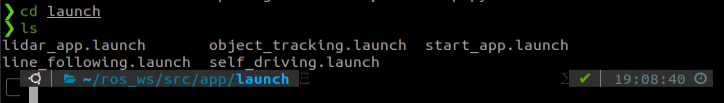
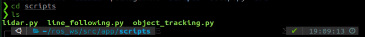
The following explains the application files using /ros_ws/src/app as an example.
Navigate to the directory containing the gameplay files, where two folders can be found: launch and scripts.
cd /ros_ws/src/app

The launch folder contains the launch files, while scripts holds the source code for the feature.
1.14.2 Introduction to ROS2 File Directory
Open the ROS2 terminal, enter the command line, type ls, and press Enter to view the files in the home directory.
ls
Folder descriptions:.
| Directory Name | Function |
|---|---|
| wifi_manager | Wi-Fi management tool |
| software | Directory for installed software |
| ros2_ws | Workspace containing all feature functionalities |
| third_party | Directory for additional ROS2 packages, such as trained YOLOv8 models |
| Music | Music files |
| Pictures | Directory storing images |
| Public | User-defined folder |
| Templates | User-defined template folder |
| Videos | Video storage |
Enter the command cd ros2_ws/ and press Enter to access the robot workspace directory, then type ls to list the files and folders inside.
cd ros2_ws/
ls
Folder descriptions:.
| Directory/File Name | Description |
|---|---|
| build | Build space which stores cache files generated during compilation |
| command | Contains command files for implementing various functions, making them easy to locate. |
| install | Contains compiled target files and executables |
| log | Folder for storing log files |
| src | Source code folder for function packages |
Enter the command cd ros2_ws/src and press Enter to access the robot workspace directory, then type ls to list the files and folders inside.
cd ros2_ws/src
ls
Folder descriptions:.
| Directory Name | Type Description | Function |
|---|---|---|
| app | App feature directory | Gesture control, Lidar, line tracking, etc. |
| interfaces | Communication interface files | ROS message and service communication files |
| slam | Mapping features | Map generation and saving |
| bringup | System services | Launches app, wireless controller control, etc. |
| multi | Multi-robot features | Includes multi-robot mapping, multi-robot navigation, and more |
| large_models_examples | Directory for large model examples | Contains the large model feature examples |
| large_models | Directory for large model communication interfaces | ROS message and service communication files |
| calibration | Calibration parameters | IMU, linear velocity, angular velocity calibration |
| navigation | Navigation features | Waypoint publishing, RViz navigation, etc. |
| xf_mic_asr_offline | Voice control features | Voice-controlled functions |
| xf_mic_asr_offline_msgs | Directory for voice control communication interfaces | Contains ROS message and service communication files |
| driver | Driver files | Kinematics, communication between the main controller and the STM32 controller |
| peripherals | Peripheral setup | Different Lidar models, wireless controller control, keyboard control, etc. |
| example | Example projects | Creative demos: gesture control, posture control, color tracking, etc. |
| simulations | Directory for simulation files | Including Gazebo, URDF, and others |
Introduction to Function File Directory
Taking /ros2_ws/src/app as an example, the feature files are organized as follows:
Navigate to the directory containing the gameplay files, where two folders can be found: launch and app.
cd ros2_ws/src/app

The launch folder contains the launch files, while the app holds the source code for the feature.


1.15 Image Flashing
1.15.1 Preparation
Hardware:
For Jetson Nano and Raspberry Pi 5 versions, prepare an SD card with a capacity suitable for the image. In the example shown on the left, a 64GB SD card is used. Also, prepare a card reader and a computer, with Windows 10 recommended as the operating system.
For Jetson Nano and Raspberry Pi 5 versions, prepare an SD card with a capacity suitable for the image. In the example shown on the left, a 64GB SD card is used. Also prepare a card reader and a computer, with Windows 10 recommended as the operating system.
Software:
A disk initialization tool called DiskGenius.exe and an image burning tool called Win32DiskImager. This section uses these two tools as examples.
Note
Before burning the image, you can use the disk initialization tool provided in 2. Software\3. Image Burning Tools\1. Disk Formatting Tool to delete all extra partitions on the SD card.
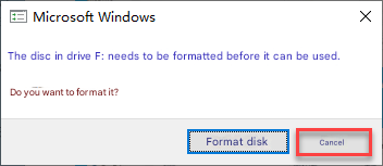
After the image is written, the system may prompt you with multiple partitions appearing as separate drives. Do not format them, simply cancel the prompts.
1.15.2 SD Card / SSD Formatting
Note
If the SD card or SSD is blank, formatting is not required.
Remove the SD card from Jetson Nano, Jetson Orin Nano, or Raspberry Pi 5. For SSDs, remove them from the Jetson Orin Nano or the Jetson Orin NX.
Jetson Nano / Jetson Orin Nano
Raspberry Pi 5
Jetson Orin NX
In the provided materials, locate the compressed package under 2. Softwares \ 3. Image Flashing Tools \ 1. Disk Formatting Tool, extract it, and open DiskGenius.exe to format the SD card or SSD. Make sure you select the correct drive. Choosing the wrong drive may result in formatting your computer’s hard disk.
After inserting the SD card or SSD into the computer, you will see an additional drive letter appear besides those of your computer’s own drives.
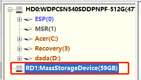
Right-click the SD card drive and select Delete All Partitions.
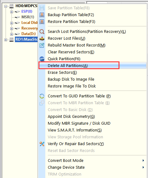
As shown in the figure below:
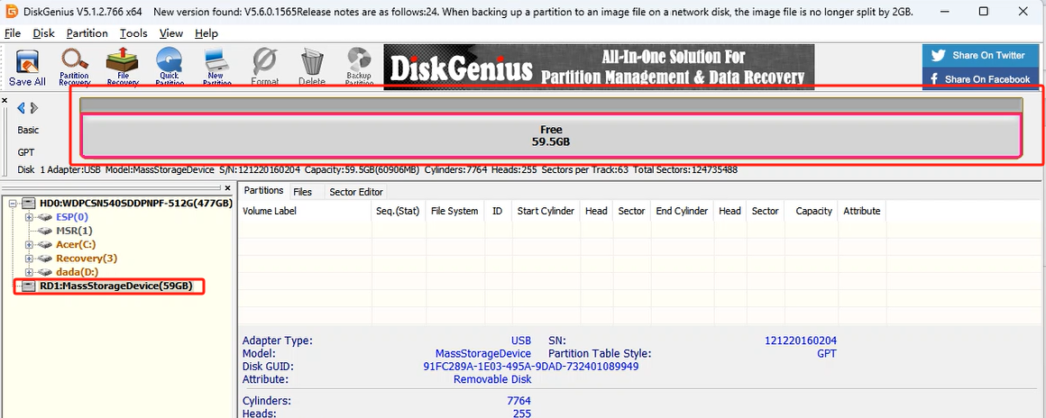
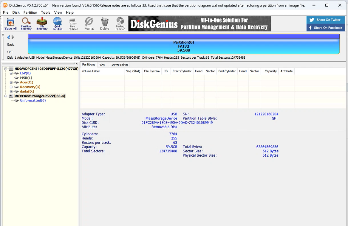
Once deleted, create a new partition so the computer can recognize the SD card. Confirm any pop-up prompts.
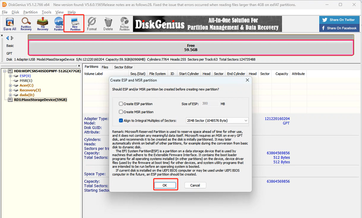
Then click Save All.
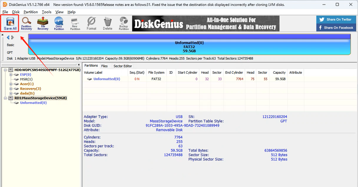
When complete, the SD card or SSD is formatted successfully.
1.15.3 Image Flashing
Open Win32DiskImager and click the icon
 to select the image file. Download and extract it beforehand, and the image shown in the examples is for reference only. In the Device field, select the SD card or SSD drive letter, then click Write to start burning the image.
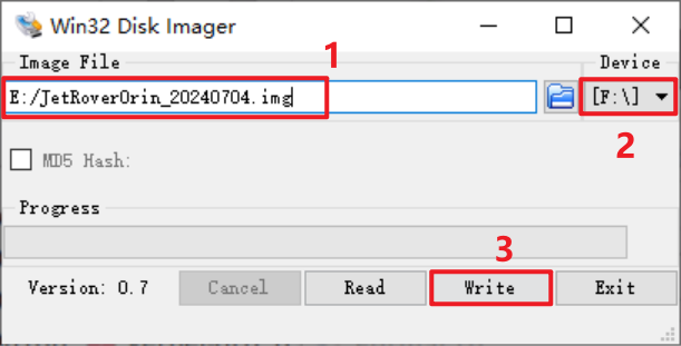
Note
The image file path must contain only English characters.
If prompted with the figure below, click Yes to continue.
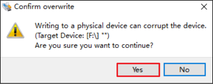
Once you see Write Successful, the image has been written successfully. If an error occurs, disable firewall software, reinsert the SD card or SSD, and repeat the steps in this section.
Note
Once the image has been successfully written, any prompt asking to format the partition can be ignored.
After the burning is complete, reinsert the SD card or SSD into the controller. Power it on, wait a few moments, and the system will boot successfully.