4. ROS+Open CV Course
4.1 Single Color Recognition
4.1.1 Brief Overview of Operation
In this section, the camera is used to detect colors. When a red object is recognized, it will be circled on the screen and the message “Color: red” will be printed.
The implementation of color recognition is divided into two parts: color detection and response execution.
In the recognition process, Gaussian filtering is first applied to reduce noise in the image. Then, the image is converted to the Lab color space to better distinguish colors.
Based on this, color thresholds are used to identify the color of the object within the circle. A mask is then applied to the image, which involves selecting parts of the image, graphics, or objects to globally or locally block out areas in the image for processing.
After masking, morphological operations including opening and closing are performed on the object image to refine the results.
Opening operation: Involves erosion followed by dilation. Effect: Removes small objects, smooths object boundaries, and does not affect object area, and helps eliminate small noise and separates connected objects.
Closing operation: Involves dilation followed by erosion. Effect: Fills small holes inside objects, connect adjacent objects, and bridge broken contours, while also smoothing boundaries without changing the area.
Once the recognition is complete, the buzzer is configured so that the robot can respond based on the detection. For detailed feedback behaviors corresponding to different detections, please refer to 4.1.3 Project Outcome of this document.
4.1.2 Enabling and Disabling the Feature
Note
When entering commands, be sure to use correct case and spacing. You can use the Tab key to auto-complete keywords.
(1) Power on the device and connect via VNC remote desktop tool.

(2) Click the terminal icon  in the upper-left corner of the system desktop to open a command-line window.

(3) Enter the following command and press Enter to navigate to the directory where the feature’s program is stored:
cd /home/ubuntu/ros2_ws/src/example/example
(4) Enter the following command and press Enter to start the feature.
python3 color_warning.py
(5) To exit the feature, press Ctrl+C in the terminal. If the feature does not exit immediately, press Ctrl+C multiple times.
4.1.3 Project Outcome
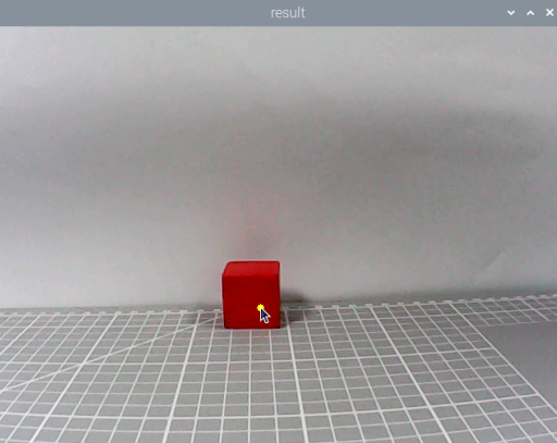
When the feature is activated, the camera is used to detect colors. When a red object is recognized, it will be circled on the screen and the message “Color: red” will be printed.
Note
For best results, perform traffic sign recognition in a well-lit environment to avoid errors caused by poor lighting.
During the recognition process, avoid having objects in the camera’s field of view that are similar or identical in color to the target object, as this may cause misidentification.
If the color recognition is inaccurate, refer to the section “4.1.5 Feature Extensions → Adjusting Color Thresholds” in this document to configure the color threshold settings.
4.1.4 Program Brief Analysis
The source code for this demo is located at /home/ubuntu/ros2_ws/src/example/example/color_warning.py
Import the Necessary Libraries
(1) In Python, libraries are imported using the import statement. In this program, libraries such as cv2 for image processing, numpy for numerical computation, and rclpy for the ROS2 framework are included to support image operations, mathematical calculations, and robot control.
4 5 6 7 8 9 10 11 12 13 14 15 | import cv2 import math import time import threading import numpy as np import rclpy from rclpy.node import Node from sensor_msgs.msg import Image from ros_robot_controller_msgs.msg import BuzzerState, RGBStates from cv_bridge import CvBridge import sdk.yaml_handle as yaml_handle import sdk.Misc as Misc |
(2) Other commonly used libraries include those for OpenCV, time management, mathematics, and threading. To call a function from a library, use the format of library_name.function_name(parameter1, parameter2, …)
68 | time.sleep(0.01) |
For example, calling time.sleep() uses the sleep function from the time library, which creates a delay.
Python also includes built-in libraries such as time, cv2, and math, which can be imported and used directly. Additionally, custom libraries can be created and used. For instance, the previously mentioned “yaml_handle” file is a user-defined module for reading data.
Aliasing Function Libraries
Some library names may be long or hard to remember. To simplify function calls, aliases are often used. For example:
14 | import sdk.yaml_handle as yaml_handle |
After aliasing, functions from the ros_robot_controller_sdk library can be called in a format of yaml_handle.function_name(parameter1, parameter2), which makes the code more convenient and easier to read.
55 | lab_data = yaml_handle.get_yaml_data(yaml_handle.lab_file_path) |
Main Function Analysis
In Python, the main function of a program is defined as “__name__ == ‘__main__:’”.
(1) Converting ROS Image Messages to Usable Images
87 88 | # Convert ROS image message to OpenCV image (将ROS图像消息转换为OpenCV图像) img = self.bridge.imgmsg_to_cv2(msg, "bgr8") |
When the feature is activated, the system retrieves an image from the ROS image message and stores it in the variable img.
(2) Image Processing
When an image is received, the run() function is triggered for image processing.
90 91 | # Process image and detect color (处理图像并检测颜色) frame = self.run(img) |
(3) Gaussian Blur
Images often contain noise, which can reduce clarity and make it harder to detect features. To reduce noise, different filtering methods can be applied depending on the type of noise. Common techniques include Gaussian blur, Median blur, and Mean blur.
Gaussian blur is a linear smoothing filter especially effective for reducing Gaussian noise. It’s widely used in image processing for denoising.
107 | frame_gb = cv2.GaussianBlur(frame_resize, (3, 3), 3) |
First parameter: frame_resize – the input image
Second parameter: (3, 3) – the size of the Gaussian kernel
Third parameter: 3 – the standard deviation in the X direction
(4) Convert Image to LAB Color Space
Use the cv2.cvtColor() function to convert between color spaces.
108 | frame_lab = cv2.cvtColor(frame_gb, cv2.COLOR_BGR2LAB) |
First parameter: frame_gb – the input image
Second parameter: cv2.COLOR_BGR2LAB – conversion code that converts BGR format to LAB. If you want to convert from BGR to RGB instead, use cv2.COLOR_BGR2RGB.
(5) Convert Image to Binary Format
Binary images contain only 0 and 1 values, making them simpler and easier to process. The cv2.inRange() function is used to perform thresholding.
115 116 117 118 119 | for color_name, color_data in lab_data.items(): if color_name not in ['black', 'white']: frame_mask = cv2.inRange(frame_lab, (color_data['min'][0], color_data['min'][1], color_data['min'][2]), (color_data['max'][0], color_data['max'][1], color_data['max'][2])) |
First parameter: frame_lab – the input image
Second parameter: (lab_data[i]['min'][0], lab_data[i]['min'][1], lab_data[i]['min'][2]) – lower bound for LAB threshold
Third parameter: (lab_data[i]['max'][0], lab_data[i]['max'][1], lab_data[i]['max'][2]) – upper bound for LAB threshold
To reduce noise and create smoother binary images, erosion and dilation operations are applied. These are basic morphological operations commonly used in image processing, especially for binary images. They help remove small noise, separate or identify objects, and adjust image size.
121 122 | eroded = cv2.erode(frame_mask, cv2.getStructuringElement(cv2.MORPH_RECT, (3, 3))) dilated = cv2.dilate(eroded, cv2.getStructuringElement(cv2.MORPH_RECT, (3, 3))) |
The first parameter is the input image.
The second parameter is the structuring element (kernel), which defines the nature of the operation. The size and shape of the kernel determine the intensity of erosion and dilation.
(6) Obtaining the Largest Contour
After the above processing, contour detection is used to identify the target object. The cv2.contourArea() function from the cv2 library is used.
152 153 154 155 156 157 158 159 160 161 | def get_area_max_contour(self, contours): """Get the largest contour (获取最大轮廓)""" max_area = 0 max_contour = None for c in contours: area = math.fabs(cv2.contourArea(c)) if area > max_area and area > 50: max_area = area max_contour = c return max_contour, max_area |
The variable max_area stores the largest contour area found, initially set to 0.
The variable max_contour stores the contour with the largest area, initially set to None.
The cv2.contourArea() function calculates the area of each contour.
To decide whether the contour’s area is larger than max_area and greater than 50. If it is true, update max_area with the current area and max_contour with the current contour c.
157 158 159 160 | area = math.fabs(cv2.contourArea(c)) if area > max_area and area > 50: max_area = area max_contour = c |
(7) Displaying the Output
93 94 95 96 97 98 | # Display processed image (显示处理后的图像) cv2.imshow('Frame', frame) key = cv2.waitKey(1) if key == 27: # Exit with ESC (按ESC退出) self.destroy_node() cv2.destroyAllWindows() |
The cv2.resize() function resizes the processed image to an appropriate display size.
The cv2.imshow() function displays the image in a window.
'frame' is the window name and frame_resize is the image to display. To ensure the window functions correctly, cv2.waitKey() must be included.
This function waits for a key input. The parameter 1 specifies the delay time.
Subthread Analysis
(1) Activating the RGB LED
The RGB LED color matches the detected color.
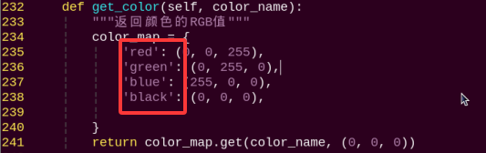
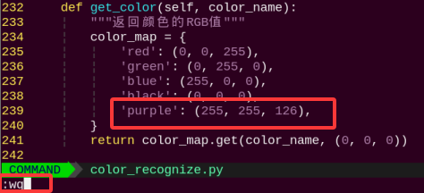
163 164 165 166 167 168 169 170 171 172 | def get_color(self, color_name): """Return RGB value of the color (返回颜色的RGB值)""" color_map = { 'red': (0, 0, 255), 'green': (0, 255, 0), 'blue': (255, 0, 0), 'black': (0, 0, 0), 'purple':(255, 255, 126), } return color_map.get(color_name, (0, 0, 0)) |
(2) Triggering the Buzzer
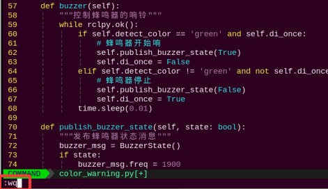
59 60 61 62 63 64 65 66 67 68 | while rclpy.ok(): if self.detect_color == 'red' and self.di_once: # Buzzer starts ringing (蜂鸣器开始响) self.publish_buzzer_state(True) self.di_once = False elif self.detect_color != 'red' and not self.di_once: # Buzzer stops (蜂鸣器停止) self.publish_buzzer_state(False) self.di_once = True time.sleep(0.01) |
The self.publish_buzzer_state(True) method is called to activate the buzzer. True turns the buzzer on, and False turns it off. The di_once attribute is set to True to indicate that the red color detection has already been processed, preventing the buzzer from responding repeatedly.
The line time.sleep(0.1) is used to delay for 0.1 seconds, which determines how long the buzzer stays active.
4.1.5 Feature Extensions
Adjusting Color Thresholds
If the color recognition does not perform well during usage, the color thresholds may need to be adjusted. This section uses red as an example. The same procedure applies to other colors. Follow the steps below:
Note
By default, the system launches the threshold adjustment tool automatically on startup. You can simply click the icon
 to open it.
If the tool does not start automatically, open the command-line terminal and enter the following command, then press Enter:
ros2 launch peripherals usb_cam.launch.py
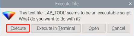
(1) Double-click the desktop icon and click Execute in the pop-up dialog.

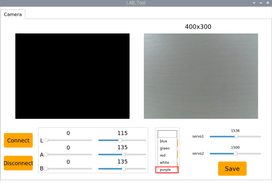
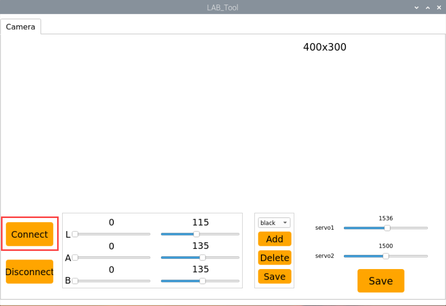
(2) Once the interface opens, click Connect.

(3) After a successful connection, select red from the color options in the lower-right corner of the interface.
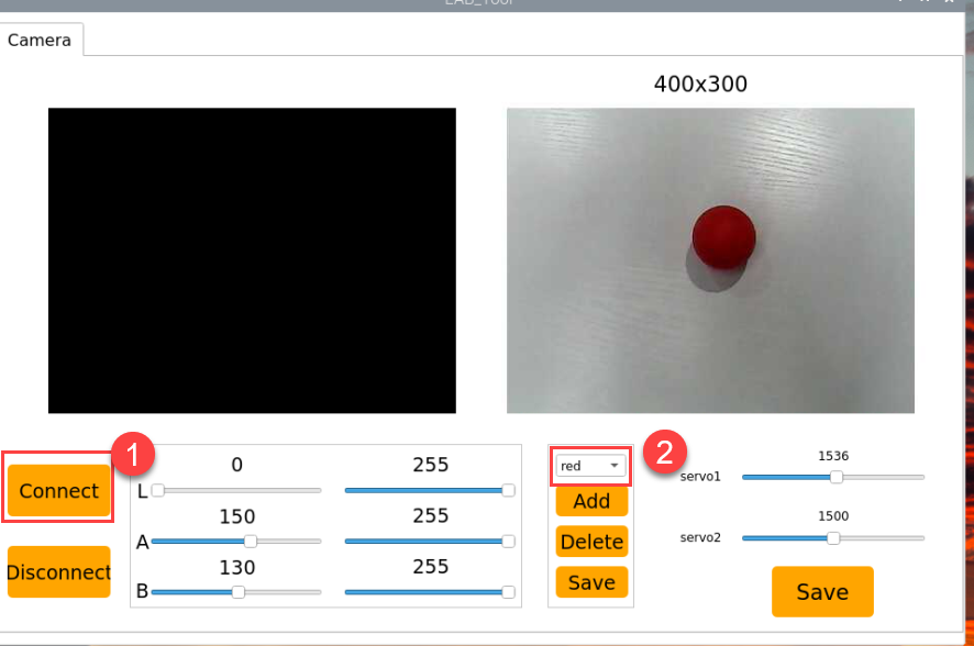
(4) If no image appears in the preview window, the camera may not be connected correctly. Please check the camera cable.
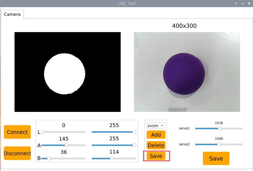
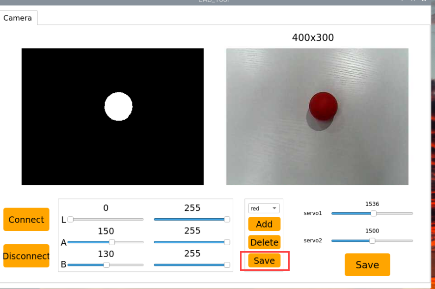
On the right side of the interface, you will see the live camera feed. On the left side is the color area to be sampled. Point the camera at a red color sample, then adjust the six sliders below the image until the red area on the left turns completely white, and all other areas become black. Then, click Save to save the adjusted threshold settings.

Changing the Default Recognized Color
The color recognition program includes three preset colors: red, green, and blue. By default, the system recognizes red — when detected, the buzzer sounds, a red frame appears in the live feed, and the message “Color: red” is printed.
To change the default color to green, follow these steps:
(1) Open the terminal and navigate to the source code directory.
cd /home/ubuntu/ros2_ws/src/example/example
(2) Enter the command to open the program file and press Enter.
vim color_warning.py
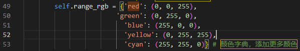
(3) Locate the line in the code as shown below.
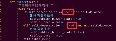
(4) Press the i key to enter edit mode.
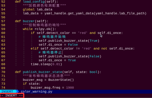
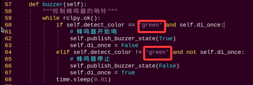
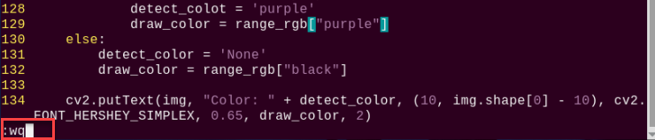
(5) Modify the highlighted line by changing the value to “green”.
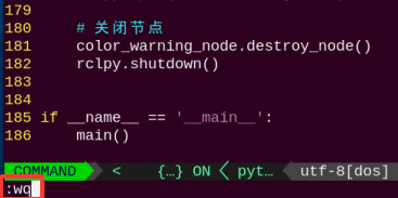
(6) Next to save the changes. Press the Esc key, then type the command “:wq” and press Enter to save and exit.
(7) Return to the terminal where enters the source code directory and run the color recognition program with:
python3 color_warning.py
Adding a New Recognizable Color
Besides the three built-in colors, users can define additional colors. The following example shows how to add purple as a new recognizable color:
(1) Double-click the desktop icon and click Execute in the pop-up dialog.
(2) In the opened window, click Connect.
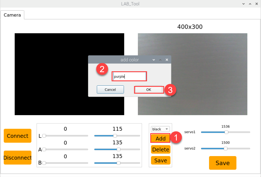
(3) Click Add, enter a name for the new color (e.g., purple), and click OK.

(4) Use the dropdown menu in the color selector to choose purple.

(5) Point the camera at a purple object. Adjust the L, A, and B sliders until the target area turns white on the left side of the screen, while other areas turn black.

(6) Click Save to store the new threshold settings.
(7) After completing the modifications, you can verify whether the new values have been successfully saved by entering the following command and pressing Enter to navigate to the program directory.
cd /home/ubuntu/software/lab_tool
(8) Open the program file by entering the command.
vim lab_config.yaml
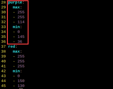
(9) You should now be able to see the purple color threshold values.
(10) Then follow steps 1 to 4 of Changing the Default Recognized Color again to open the program file, press the “i” key to enter edit mode, and locate the section of code as shown in the figure below.
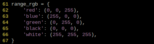
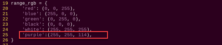
Manually add the new entry “’purple’:(255, 255, 114),”. As shown in the figure below, (255, 255, 114) corresponds to the max values observed earlier.
'purple':(255, 255, 114),
(11) Next to save the changes. Press the Esc key, then type the command “:wq” and press Enter to save and exit.
(12) Finally, launch the color recognition program again referring to 4.1.2 Enabling and Disabling the Feature. Place a purple object in front of the camera—you should see a purple bounding box in the live view and the message “purple” printed in the terminal. To set purple as the default color, simply update the value in the program code as shown in Changing the Default Recognized Color.
(13) If you want to add more colors for recognition, refer to the steps above for guidance.
4.2 Color Recognition
4.2.1 Brief Overview of Operation
In this section, the camera is used for color recognition. When red is detected, the gimbal will “nod”, and when blue or green is detected, it will “shake its head.”
The implementation of color recognition is divided into two parts: color detection and response execution.
In the recognition process, Gaussian filtering is first applied to reduce noise in the image. Then, the image is converted to the Lab color space to better distinguish colors.
Based on this, color thresholds are used to identify the color of the object within the circle. A mask is then applied to the image, which involves selecting parts of the image, graphics, or objects to globally or locally block out areas in the image for processing.
After masking, morphological operations including opening and closing are performed on the object image to refine the results.
Opening operation: Involves erosion followed by dilation. Effect: Removes small objects, smooths object boundaries, and does not affect object area, and helps eliminate small noise and separates connected objects.
Closing operation: Involves dilation followed by erosion. Effect: Fills small holes inside objects, connect adjacent objects, and bridge broken contours, while also smoothing boundaries without changing the area.
After color recognition, the servo, buzzer, and RGB light are configured to trigger different responses based on the detected color. For example, when red is detected, the robot will “nod”, the buzzer will beep once, and the RGB light will turn red.
For a complete list of gesture-action mappings, refer to the section 3. Project Outcome of this document.
4.2.2 Enabling and Disabling the Feature
Note
When entering commands, be sure to use correct case and spacing. You can use the Tab key to auto-complete keywords.
(1) Power on the device and connect via VNC remote desktop tool.

(2) Click the terminal icon  in the upper-left corner of the system desktop to open a command-line window.

(3) Enter the following command and press Enter to navigate to the directory where the feature’s program is stored:
cd /home/ubuntu/ros2_ws/src/example/example
(4) Enter the following command and press Enter to start the feature.
python3 color_recognize.py
(5) To exit the feature, press Ctrl+C in the terminal. If the feature does not exit immediately, press Ctrl+C multiple times.
4.2.3 Project Outcome
After the feature is activated, the camera responds to different colors with corresponding actions. The behavior is shown in the table below:
| Object Color | Buzzer | RGB Light | Action | Printed Outpt |
|---|---|---|---|---|
| Red | Beeps once | Red | Nod | red |
| Green | Beeps once | Green | Shake Head | green |
| Blue | Beeps once | Blue | Shake Head | blue |
Note
For best results, perform traffic sign recognition in a well-lit environment to avoid errors caused by poor lighting.
During the recognition process, avoid having objects in the camera’s field of view that are similar or identical in color to the target object, as this may cause misidentification.
If the color recognition is inaccurate, refer to the section “4.2.5 Feature Extensions → Adjusting Color Threshold” in this document to configure the color threshold settings.
4.2.4 Program Brief Analysis
The source code for this demo is located at /home/ubuntu/ros2_ws/src/example/example/color_recognize.py
Import the Necessary Libraries
(1) In Python, libraries are imported using the import statement. In this program, libraries such as cv2 for image processing, numpy for numerical computation, and rclpy for the ROS 2 framework are included to support image operations, mathematical calculations, and robot control.
4 5 6 7 8 9 10 11 12 13 14 15 | import cv2 import math import time import threading import numpy as np import rclpy from rclpy.node import Node from sensor_msgs.msg import Image from ros_robot_controller_msgs.msg import BuzzerState, RGBStates, SetPWMServoState, PWMServoState, RGBState # 导入 RGBState from cv_bridge import CvBridge import sdk.yaml_handle as yaml_handle import sdk.Misc as Misc |
(2) Other commonly used libraries include those for OpenCV, time management, mathematics, and threading. To call a function from a library, use the format of library_name.function_name(parameter1, parameter2, …)
79 | time.sleep(0.01) |
For example, calling time.sleep() uses the sleep function from the time library, which creates a delay.
Python also includes built-in libraries such as time, cv2, and math, which can be imported and used directly. Additionally, custom libraries can be created and used. For instance, the previously mentioned “yaml_handle” file is a user-defined module for reading data.
(3) Aliasing Function Libraries
Some library names may be long or hard to remember. To simplify function calls, aliases are often used. For example:
14 | import sdk.yaml_handle as yaml_handle |
After aliasing, functions from the ros_robot_controller_sdk library can be called in a format of yaml_handle.function_name(parameter1, parameter2), which makes the code more convenient and easier to read.
Main Function Analysis
In Python, the main function of a program is defined as “__name__ == ‘__main__:’”. The program begins by calling the init() function to perform initialization. In this case, initialization includes resetting the servo to its initial position and reading the color threshold configuration file. Other typical initialization tasks may involve setting up ports, peripherals, and timers.
270 271 272 273 274 275 276 277 278 279 280 281 282 283 284 | def main(): rclpy.init() color_warning_node = ColorWarningNode() try: rclpy.spin(color_warning_node) finally: # Perform cleanup before exiting (退出前进行清理) color_warning_node.running = False # Set flag to stop the thread (设置标志以停止线程) color_warning_node.destroy_node() # Ensure the node is destroyed (确保销毁节点) rclpy.shutdown() cv2.destroyAllWindows() # Ensure OpenCV windows are closed (确保关闭 OpenCV 窗口) if __name__ == '__main__': main() |
(1) Capture Camera Image
96 97 98 99 100 101 | def image_callback(self, msg): """Process image from camera (处理从摄像头获取的图像)""" # Convert ROS image message to OpenCV image (将ROS图像消息转换为OpenCV图像) img = self.bridge.imgmsg_to_cv2(msg, "bgr8") with self.lock: self.current_image = img |
When the feature starts, the image captured by the camera is stored in the variable img.
(2) Image Processing
When an image is received, the run() function is triggered for image processing.
107 108 109 110 111 112 113 114 | with self.lock: if self.current_image is not None: img = self.current_image.copy() self.current_image = None if img is not None: frame = self.run(img) cv2.imshow('Frame', frame) key = cv2.waitKey(1) |
The function img.copy() is used to copy the contents of img to a new variable called frame.
The run() function handles image processing.
122 123 124 125 126 127 128 129 130 131 132 133 134 135 136 137 138 139 140 141 142 143 144 145 146 147 148 149 150 | def run(self, img): """Color detection processing (颜色检测处理)""" img_copy = img.copy() img_h, img_w = img.shape[:2] frame_resize = cv2.resize(img_copy, (320, 240), interpolation=cv2.INTER_NEAREST) frame_gb = cv2.GaussianBlur(frame_resize, (3, 3), 3) frame_lab = cv2.cvtColor(frame_gb, cv2.COLOR_BGR2LAB) max_area = 0 color_area_max = None areaMaxContour_max = 0 # Traverse color ranges from config file for detection (遍历配置文件中的颜色范围进行颜色检测) for color_name, color_data in lab_data.items(): if color_name not in ['black', 'white']: frame_mask = cv2.inRange(frame_lab, (color_data['min'][0], color_data['min'][1], color_data['min'][2]), (color_data['max'][0], color_data['max'][1], color_data['max'][2])) eroded = cv2.erode(frame_mask, cv2.getStructuringElement(cv2.MORPH_RECT, (3, 3))) dilated = cv2.dilate(eroded, cv2.getStructuringElement(cv2.MORPH_RECT, (3, 3))) contours = cv2.findContours(dilated, cv2.RETR_EXTERNAL, cv2.CHAIN_APPROX_NONE)[-2] areaMaxContour, area_max = self.get_area_max_contour(contours) if areaMaxContour is not None: # Ensure areaMaxContour exists (确保 areaMaxContour 存在) if area_max > max_area: max_area = area_max color_area_max = color_name areaMaxContour_max = areaMaxContour |
(3) Resize the Image for Easier Processing
127 | frame_resize = cv2.resize(img_copy, (320, 240), interpolation=cv2.INTER_NEAREST) |
The first parameter img_copy is the input image.
The second parameter (320, 240) specifies the output image size. You can adjust this size as needed.
Parameter 3: interpolation=cv2.INTER_NEAREST – Interpolation method.
INTER_NEAREST: Nearest neighbor interpolation.
INTER_LINEAR: Bilinear interpolation, default if unspecified.
INTER_CUBIC: Bicubic interpolation using a 4×4 pixel neighborhood.
INTER_LANCZOS4: Lanczos interpolation using an 8×8 neighborhood.
(4) Gaussian Blur
Images often contain noise, which can reduce clarity and make it harder to detect features. To reduce noise, different filtering methods can be applied depending on the type of noise. Common techniques include Gaussian blur, Median blur, and Mean blur.
Gaussian blur is a linear smoothing filter especially effective for reducing Gaussian noise. It’s widely used in image processing for denoising.
128 | frame_gb = cv2.GaussianBlur(frame_resize, (3, 3), 3) |
First parameter: frame_resize – the input image
Second parameter: (3, 3) – the size of the Gaussian kernel
Third parameter: 3 – the standard deviation in the X direction
(5) Convert the image to LAB color space, the function cv2.cvtColor() is used to convert the color space of an image.
129 | frame_lab = cv2.cvtColor(frame_gb, cv2.COLOR_BGR2LAB) |
First parameter: frame_gb – the input image
Second parameter: cv2.COLOR_BGR2LAB – conversion code that converts BGR format to LAB. If you want to convert from BGR to RGB instead, use cv2.COLOR_BGR2RGB.
(6) Convert images to binary images which contain only 0 and 1 values, making them simpler and easier to process.
The cv2.inRange() function is used to perform thresholding.
138 139 140 | frame_mask = cv2.inRange(frame_lab, (color_data['min'][0], color_data['min'][1], color_data['min'][2]), (color_data['max'][0], color_data['max'][1], color_data['max'][2])) |
First parameter: frame_lab – the input image
The second parameter (color_data[i]['min'][0], color_data[i]['min'][1], color_data[i]['min'][2]) defines the lower bound of the color threshold.
The third parameter (color_data[i]['max'][0], color_data[i]['max'][1], color_data[i]['max'][2]) defines the upper bound of the color threshold.
(7) To refine the initial color mask image during color detection—removing noise, smoothing contours, and accurately extracting and analyzing objects of a specific color—morphological operations and contour detection using the OpenCV library are applied.
141 142 143 144 | eroded = cv2.erode(frame_mask, cv2.getStructuringElement(cv2.MORPH_RECT, (3, 3))) dilated = cv2.dilate(eroded, cv2.getStructuringElement(cv2.MORPH_RECT, (3, 3))) contours = cv2.findContours(dilated, cv2.RETR_EXTERNAL, cv2.CHAIN_APPROX_NONE)[-2] areaMaxContour, area_max = self.get_area_max_contour(contours) |
In the first line, the first parameter frame_mask is the input image.
The second parameter cv2.getStructuringElement(cv2.MORPH_RECT, (3, 3)) defines the structuring element. The function cv2.getStructuringElement() is used to create a structuring element. During the erosion process, if all pixels covered by the structuring element are not foreground pixels (value = 255), the center pixel is set to a background pixel (value = 0), which results in erosion.
In the second line, the first parameter eroded is the image after erosion, used here as the input for dilation.
The second parameter cv2.getStructuringElement(cv2.MORPH_RECT, (3, 3)) again creates a 3×3 rectangular structuring element. In the dilation operation, if any pixel within the area covered by the structuring element is a foreground pixel (value = 255), the center pixel is set to a foreground pixel, which expands the foreground region.
(8) Obtaining the Largest Contour
After the above processing, contour detection is used to identify the target object. The findContours() function from the cv2 library is used.
143 | contours = cv2.findContours(dilated, cv2.RETR_EXTERNAL, cv2.CHAIN_APPROX_NONE)[-2] |
The first parameter dilated is the input image used for contour detection.
The second parameter cv2.RETR_EXTERNAL is the contour retrieval mode.
The third parameter cv2.CHAIN_APPROX_NONE)[-2] is the contour approximation method.
Among the detected contours, the one with the largest area is selected. To avoid interference, a minimum area threshold is set. Only contours with an area larger than this threshold are considered valid targets.
221 222 223 224 225 226 227 228 229 230 | def get_area_max_contour(self, contours): """Get the largest contour (获取最大轮廓)""" max_area = 0 max_contour = None for c in contours: area = math.fabs(cv2.contourArea(c)) if area > max_area and area > 50: max_area = area max_contour = c return max_contour, max_area |
(9) A conditional statement is used to determine which color in the image has the largest area.
146 147 148 149 150 | if areaMaxContour is not None: # Ensure areaMaxContour exists (确保 areaMaxContour 存在) if area_max > max_area: max_area = area_max color_area_max = color_name areaMaxContour_max = areaMaxContour |
(10) Displaying the Output
127 | frame_resize = cv2.resize(img_copy, (320, 240), interpolation=cv2.INTER_NEAREST) |
111 112 113 114 115 116 117 118 | if img is not None: frame = self.run(img) cv2.imshow('Frame', frame) key = cv2.waitKey(1) if key == 27: # Exit with ESC (按ESC退出) self.running = False cv2.destroyAllWindows() break |
The cv2.resize() function resizes the processed image to an appropriate display size.
The cv2.imshow() function displays the image in a window.
'frame' is the window name and frame_resize is the image to display. To ensure the window functions correctly, cv2.waitKey() must be included.
This function waits for a key input. The parameter 1 specifies the delay time.
Subthread Analysis
The sub-thread function of the robot runs when a color is recognized, triggering the run() function to handle the recognized color.
This mainly involves analyzing the image processing results and executing corresponding responses, including control of RGB lights, buzzer, and other modules.
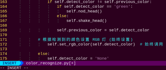
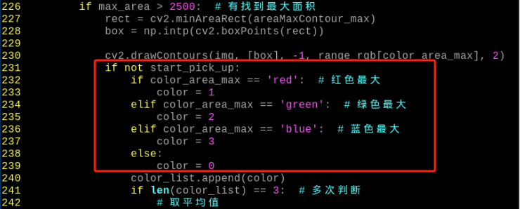
122 123 124 125 126 127 128 129 130 131 132 133 134 135 136 137 138 139 140 141 142 143 144 145 146 147 148 149 150 151 152 153 154 155 156 157 158 159 160 161 162 163 164 165 166 167 168 169 170 171 172 | def run(self, img): """Color detection processing (颜色检测处理)""" img_copy = img.copy() img_h, img_w = img.shape[:2] frame_resize = cv2.resize(img_copy, (320, 240), interpolation=cv2.INTER_NEAREST) frame_gb = cv2.GaussianBlur(frame_resize, (3, 3), 3) frame_lab = cv2.cvtColor(frame_gb, cv2.COLOR_BGR2LAB) max_area = 0 color_area_max = None areaMaxContour_max = 0 # Traverse color ranges from config file for detection (遍历配置文件中的颜色范围进行颜色检测) for color_name, color_data in lab_data.items(): if color_name not in ['black', 'white']: frame_mask = cv2.inRange(frame_lab, (color_data['min'][0], color_data['min'][1], color_data['min'][2]), (color_data['max'][0], color_data['max'][1], color_data['max'][2])) eroded = cv2.erode(frame_mask, cv2.getStructuringElement(cv2.MORPH_RECT, (3, 3))) dilated = cv2.dilate(eroded, cv2.getStructuringElement(cv2.MORPH_RECT, (3, 3))) contours = cv2.findContours(dilated, cv2.RETR_EXTERNAL, cv2.CHAIN_APPROX_NONE)[-2] areaMaxContour, area_max = self.get_area_max_contour(contours) if areaMaxContour is not None: # Ensure areaMaxContour exists (确保 areaMaxContour 存在) if area_max > max_area: max_area = area_max color_area_max = color_name areaMaxContour_max = areaMaxContour with self.lock: # Lock when accessing shared resources (在访问共享资源时加锁) if max_area > 2000: ((centerX, centerY), radius) = cv2.minEnclosingCircle(areaMaxContour_max) centerX = int(Misc.map(centerX, 0, 320, 0, img_w)) centerY = int(Misc.map(centerY, 0, 240, 0, img_h)) radius = int(Misc.map(radius, 0, 320, 0, img_w)) cv2.circle(img, (centerX, centerY), radius, self.get_color(color_area_max), 2) self.detect_color = color_area_max self.draw_color = self.get_color(color_area_max) if self.detect_color != self.previous_color: if self.detect_color == 'red': self.nod_head() else: self.shake_head() self.previous_color = self.detect_color # Set RGB light based on detected color (always set) (根据检测到的颜色设置 RGB 灯 (始终设置)) self.set_rgb_color(self.detect_color) # Always call (始终调用) |
(1) Activating the RGB LED
The RGB LED color matches the detected color.
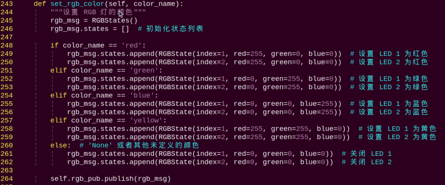
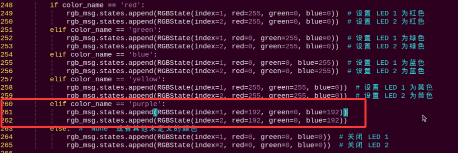
243 244 245 246 247 248 249 250 251 252 253 254 255 256 257 258 259 260 261 262 263 264 265 | def set_rgb_color(self, color_name): """Set RGB light color (设置 RGB 灯的颜色)""" rgb_msg = RGBStates() rgb_msg.states = [] # Initialize status list (初始化状态列表) if color_name == 'red': rgb_msg.states.append(RGBState(index=1, red=255, green=0, blue=0)) # Set LED 1 to red (设置 LED 1 为红色) rgb_msg.states.append(RGBState(index=2, red=255, green=0, blue=0)) # Set LED 2 to red (设置 LED 2 为红色) elif color_name == 'green': rgb_msg.states.append(RGBState(index=1, red=0, green=255, blue=0)) # Set LED 1 to green (设置 LED 1 为绿色) rgb_msg.states.append(RGBState(index=2, red=0, green=255, blue=0)) # Set LED 2 to green (设置 LED 2 为绿色) elif color_name == 'blue': rgb_msg.states.append(RGBState(index=1, red=0, green=0, blue=255)) # Set LED 1 to blue (设置 LED 1 为蓝色) rgb_msg.states.append(RGBState(index=2, red=0, green=0, blue=255)) # Set LED 2 to blue (设置 LED 2 为蓝色) elif color_name == 'yellow': rgb_msg.states.append(RGBState(index=1, red=255, green=255, blue=0)) # Set LED 1 to yellow (设置 LED 1 为黄色) rgb_msg.states.append(RGBState(index=2, red=255, green=255, blue=0)) # Set LED 2 to yellow (设置 LED 2 为黄色) elif color_name == 'purple': rgb_msg.states.append(RGBState(index=1, red=192, green=0, blue=192)) rgb_msg.states.append(RGBState(index=2, red=192, green=0, blue=192)) else: # 'None' or other undefined colors ('None' 或者其他未定义的颜色) rgb_msg.states.append(RGBState(index=1, red=0, green=0, blue=0)) # Turn off LED 1 (关闭 LED 1) rgb_msg.states.append(RGBState(index=2, red=0, green=0, blue=0)) # Turn off LED 2 (关闭 LED 2) |
(2) Triggering the Buzzer
81 82 83 84 85 86 87 88 89 90 91 92 93 94 | def publish_buzzer_state(self, state: bool): """Publish buzzer status message (发布蜂鸣器状态消息)""" buzzer_msg = BuzzerState() if state: buzzer_msg.freq = 1900 buzzer_msg.on_time = 0.2 buzzer_msg.off_time = 0.01 buzzer_msg.repeat = 1 else: buzzer_msg.freq = 0 buzzer_msg.on_time = 0.0 buzzer_msg.off_time = 0.0 buzzer_msg.repeat = 0 self.buzzer_publisher.publish(buzzer_msg) |
The function publish_buzzer_stater() is used to drive the buzzer. For example, with the code:
if state:
	buzzer_msg.freq = 1900
	buzzer_msg.on_time = 0.2
	buzzer_msg.off_time = 0.01
	buzzer_msg.repeat = 1
The first parameter 1900 is the frequency (Hz).
The second parameter 0.2 is the buzzer’s active time, in seconds.
The third parameter 0.01 is the buzzer’s off time, in seconds.
The fourth parameter 1 is the number of repetitions (default is 1).
(3) Robot Movement Execution
After determining whether the recognized color matches the preset color, the robot will perform either a nodding or shaking movement.
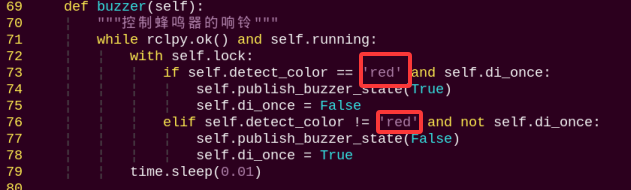
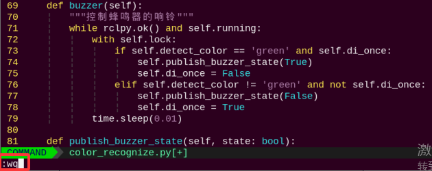
69 70 71 72 73 74 75 76 77 78 79 | def buzzer(self): """Control buzzer sound (控制蜂鸣器的响铃)""" while rclpy.ok() and self.running: with self.lock: if self.detect_color == 'red' and self.di_once: self.publish_buzzer_state(True) self.di_once = False elif self.detect_color != 'red' and not self.di_once: self.publish_buzzer_state(False) self.di_once = True time.sleep(0.01) |
189 190 191 192 193 194 195 196 197 198 199 200 201 202 203 204 | def nod_head(self): """Nodding motion (点头动作)""" self.pwm_controller([1, 1800]) time.sleep(0.3) self.pwm_controller([1, 1200]) time.sleep(0.3) self.pwm_controller([1, 1500]) time.sleep(0.3) def shake_head(self): """Shaking head motion (摇头动作)""" self.pwm_controller([2, 1200]) time.sleep(0.3) self.pwm_controller([2, 1800]) time.sleep(0.3) self.pwm_controller([2, 1500]) time.sleep(0.3) |
163 164 165 166 167 168 169 | if self.detect_color != self.previous_color: if self.detect_color == 'red': self.nod_head() else: self.shake_head() self.previous_color = self.detect_color |
The function self.pwm_controller() is used to control the PWM servo. For example, with the code self.pwm_controller([1, 1800]):
The first parameter 0.3 represents the duration of the servo movement, in seconds.
The second parameter pwm_controller is a list of servo position settings. It is a list in which each element is a tuple consisting of a servo ID and its corresponding position value.
4.2.5 Feature Extensions
Adjusting Color Threshold
If the color recognition does not perform well during usage, the color thresholds may need to be adjusted. This section uses red as an example. The same procedure applies to other colors. Follow the steps below:
Note
By default, the system launches the threshold adjustment tool automatically on startup. You can simply click the icon
 to open it.
If the tool does not start automatically, open the command-line terminal and enter the following command, then press Enter:
ros2 launch peripherals usb_cam.launch.py
(1) Double-click the desktop icon and click Execute in the pop-up dialog.
(2) Once the interface opens, click Connect to connect the camera.

(2) After a successful connection, select red from the color options in the lower-right corner of the interface.

(3) If no image appears in the preview window, the camera may not be connected correctly. Please check the camera cable.
On the right side of the interface, you will see the live camera feed. On the left side is the color area to be sampled. Point the camera at a red ball, then adjust the six sliders below the image until the red ball area on the left turns completely white, and all other areas become black. Then, click Save to save the adjusted threshold settings.
Changing the Default Recognized Color
The color recognition program includes three built-in colors: red, green, and blue. By default, when red is recognized, the camera performs a nodding motion.
Here we take changing the default color to green as an example. The specific steps are as follows:
(1) Enter the following command and press Enter to navigate to the program’s source directory.
cd /home/ubuntu/ros2_ws/src/example/example
(2) Open the program file by entering the command.
vim color_recognize.py
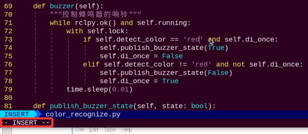
(3) In the opened file, locate the APPID section as shown in the reference image.
Note
After entering the line number in Vim, press Shift + G to jump directly to that line. The line number in the image is for reference only, please refer to the actual file.
(4) Press the i key to enter edit mode.
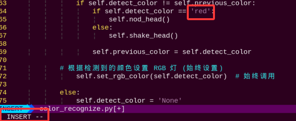
(5) When a red object is detected, the robot will nod. To change it to nod when a green object is detected, modify ‘red’ in detect_color == ‘red’ to ‘green’, as shown in the image below:
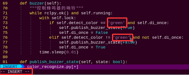
(6) When a red object is detected, the buzzer will sound. To change it so the buzzer sounds when a green object is detected, replace “red” with “green” in detect_color == ‘red’, as shown in the image below:
(7) Next to save the changes. Press the Esc key, then type the following command to save and exit:
:wq
(8) Finally, restart the color recognition program by entering the appropriate command and pressing Enter.
python3 color_recognize.py
Adding a New Recognizable Color
Besides the three built-in colors, users can define additional colors. The following example shows how to add purple as a new recognizable color:
Note
By default, the system launches the threshold adjustment tool automatically on startup. You can simply click the icon
to open it.If the tool does not start automatically, open the command-line terminal and enter the following command, then press Enter:
ros2 launch peripherals usb_cam.launch.py
(1) Double-click the desktop icon and click Execute in the pop-up dialog.
(2) In the opened window, click Connect.
(3) Click Add, enter a name for the new color (e.g., purple), and click OK.

(4) Use the dropdown menu in the color selector to choose purple.
(5) Point the camera at a purple object. Adjust the L, A, and B sliders until the target area turns white on the left side of the screen, while other areas turn black.

(6) Click Save to store the new threshold settings.

(7) After completing the modifications, you can verify whether the new values have been successfully saved by entering the following command and pressing Enter to navigate to the program directory.
cd /home/ubuntu/software/lab_tool
(8) Open the program file by entering the command.
vim lab_config.yaml
(9) You should now be able to see the purple color threshold values.

(10) Then follow steps 1 to 2 of section Changing the Default Recognized Color again to open the program file, press the “i” key to enter edit mode, and locate the section of code as shown in the figure below.
(11) Manually enter ‘purple’: (255, 255, 126) — this represents the RGB value of the color purple. Since the system uses the BGR color format, the RGB values need to be rearranged accordingly. However, in this case, the values remain (255, 255, 126) after conversion. You can look up the color’s RGB values here -> https://tools.jb51.net/static/colorpicker/.
(12) Locate the line in the code as shown below.
(13) Manually enter the content in the input box to set the onboard light on the expansion board to purple. Fill in the RGB values for purple here. You can look up the color’s RGB values at -> https://tools.jb51.net/static/colorpicker/. As shown in the figure below:
(14) Locate the line in the code as shown below.
(15) Next to save the changes. Press the Esc key, then type the following command to save and exit:
:wq
(16) Refer to 4.2.2 Enabling and Disabling the Feature in this document to restart the feature. Place a purple object in front of the camera, and the camera will perform the “shake head” action. If you want it to perform the “nod” action instead, refer to Changing the Default Recognized Color to change the default recognized color to purple.
(17) If you want to add more colors for recognition, refer to the steps above for guidance.
4.3 Color Positioning
4.3.1 Brief Overview of Operation
In this lesson, the camera can be used to recognize red, green, and blue color balls. The recognized objects will be highlighted in the return feed, and their X and Y coordinate positions will be displayed.
The implementation of color position recognition consists of two parts: color detection and position marking.
In the recognition process, Gaussian filtering is first applied to reduce noise in the image. Then, the image is converted to the Lab color space to better distinguish colors.
Based on this, color thresholds are used to identify the color of the object within the circle. A mask is then applied to the image, which involves selecting parts of the image, graphics, or objects to globally or locally block out areas in the image for processing.
After masking, morphological operations including opening and closing are performed on the object image to refine the results.
Opening operation: Involves erosion followed by dilation. Effect: Removes small objects, smooths object boundaries, and does not affect object area, and helps eliminate small noise and separates connected objects.
Closing operation: Involves dilation followed by erosion. Effect: Fills small holes inside objects, connect adjacent objects, and bridge broken contours, while also smoothing boundaries without changing the area.
Position marking requires the use of specific detection algorithms. The basic principle is to search for regions in the image that match predefined features or patterns, and then return the positions and bounding boxes of these regions.
4.3.2 Enabling and Disabling the Feature
Note
When entering commands, be sure to use correct case and spacing. You can use the Tab key to auto-complete keywords.
(1) Power on the device and connect via VNC remote desktop tool.
(2) Click the terminal icon  in the upper-left corner of the system desktop to open a command-line window.

(3) In the opened interface, enter the command to navigate to the directory where the feature program is located, and press Enter.
cd /home/ubuntu/ros2_ws/src/example/example
(4) Entering the following command and press Enter to start the feature.
python3 color_position_recognition.py
(5) To exit the feature, press Ctrl+C in the terminal. If the feature does not exit immediately, press Ctrl+C multiple times.
4.3.3 Project Outcome
The program is set by default to track red, green, and blue balls. Once the colors are successfully recognized, they will be highlighted with bounding boxes in the returned video feed, and their XY coordinates will be displayed in the lower left corner of each box.
Note
For best results, perform traffic sign recognition in a well-lit environment to avoid errors caused by poor lighting.
During the recognition process, avoid having objects in the camera’s field of view that are similar or identical in color to the target object, as this may cause misidentification.
If the color recognition is inaccurate, refer to the section “4.3.5 Feature Extensions → Adjusting Color Thresholds” in this document to configure the color threshold settings.
4.3.4 Program Brief Analysis
The source code for this demo is located at /home/ubuntu/ros2_ws/src/example/example/color_position_recognition.py
(1) In Python, libraries are imported using the import statement. In this program, libraries such as cv2 for image processing, numpy for numerical computation, and rclpy for the ROS 2 framework are included to support image operations, mathematical calculations, and robot control.
4 5 6 7 8 9 10 11 12 13 14 | import cv2 import math import time import threading import rclpy from rclpy.node import Node from sensor_msgs.msg import Image from cv_bridge import CvBridge import sdk.yaml_handle as yaml_handle import sdk.Misc as Misc import numpy as np # 确保导入 numpy |
(2) Other commonly used libraries include those for OpenCV, time management, mathematics, and threading. To call a function from a library, use the format of library_name.function_name(parameter1, parameter2, …)
88 | time.sleep(0.01) # Wait briefly if no image is available (如果没有图像,则稍作等待) |
For example, calling time.sleep() uses the sleep function from the time library, which creates a delay.
Python also includes built-in libraries such as time, cv2, and math, which can be imported and used directly. Additionally, custom libraries can be created and used. For instance, the previously mentioned yaml_handle file is a user-defined module for reading data.
(3) Aliasing Function Libraries
Some library names may be long or hard to remember. To simplify function calls, aliases are often used. For example:
4 5 6 7 8 9 10 11 12 13 14 | import cv2 import math import time import threading import rclpy from rclpy.node import Node from sensor_msgs.msg import Image from cv_bridge import CvBridge import sdk.yaml_handle as yaml_handle import sdk.Misc as Misc import numpy as np # 确保导入 numpy |
After aliasing, functions from the Misc library can be called in a format of Misc.function_name(parameter1, parameter2), which makes the code more convenient and easier to read.
(4) Main Function Analysis
In Python, the main function of a program is defined as __name__ == '__main__:. First, the camera needs to be opened and the video stream read. The read() method is used to capture each frame of the image. It then detects and marks the colored balls and displays the result. By continuously reading and displaying frames in a loop, video playback is achieved. After the video stream ends or the program is terminated, the release() function is used to free up resources.
169 170 171 172 173 174 175 176 177 178 179 180 181 182 183 | def main(): rclpy.init() color_warning_node = ColorWarningNode() try: rclpy.spin(color_warning_node) finally: # Perform cleanup before exiting (退出前进行清理) color_warning_node.running = False # Set flag to stop the thread (设置标志以停止线程) color_warning_node.destroy_node() # Ensure the node is destroyed (确保销毁节点) rclpy.shutdown() cv2.destroyAllWindows() # Ensure OpenCV windows are closed (确保关闭 OpenCV 窗口) if __name__ == '__main__': main() |
(5) Image Processing
The run() function handles image processing.
90 91 92 93 94 95 96 97 98 99 100 101 102 103 | def run(self, img): """Color detection processing (颜色检测处理)""" img_copy = img.copy() img_h, img_w = img.shape[:2] if not self.__isRunning: # Check if the program is enabled, return the original image if not enabled(检测是否开启玩法,没有开启则返回原图像) return img frame_resize = cv2.resize(img_copy, self.size, interpolation=cv2.INTER_NEAREST) frame_gb = cv2.GaussianBlur(frame_resize, (3, 3), 3) frame_lab = cv2.cvtColor(frame_gb, cv2.COLOR_BGR2LAB) # Convert the image to the LAB space(将图像转换到LAB空间) max_area = 0 areaMaxContour = None #fixed |
(6) Resize the Image
98 | frame_resize = cv2.resize(img_copy, self.size, interpolation=cv2.INTER_NEAREST) |
The first parameter img_copy is the input image.
The second parameter self.size specifies the output image size. You can adjust this size as needed.
Parameter 3: interpolation=cv2.INTER_NEAREST – Interpolation method.
INTER_NEAREST: Nearest neighbor interpolation.
INTER_LINEAR: Bilinear interpolation, default if unspecified.
INTER_CUBIC: Bicubic interpolation using a 4×4 pixel neighborhood.
INTER_LANCZOS4: Lanczos interpolation using an 8×8 neighborhood.
(7) Gaussian Blur
Images often contain noise, which can reduce clarity and make it harder to detect features. To reduce noise, different filtering methods can be applied depending on the type of noise. Common techniques include Gaussian blur, Median blur, and Mean blur.
Gaussian blur is a linear smoothing filter especially effective for reducing Gaussian noise. It’s widely used in image processing for denoising.
99 | frame_gb = cv2.GaussianBlur(frame_resize, (3, 3), 3) |
First parameter: frame_resize – the input image
Second parameter: (3, 3) – the size of the Gaussian kernel
Third parameter: 3 – the standard deviation in the X direction
(8) Convert Image to LAB Color Space
Use the cv2.cvtColor() function to convert between color spaces.
100 | frame_lab = cv2.cvtColor(frame_gb, cv2.COLOR_BGR2LAB) # Convert the image to the LAB space(将图像转换到LAB空间) |
First parameter: frame_gb – the input image
Second parameter: cv2.COLOR_BGR2LAB – conversion code that converts BGR format to LAB. If you want to convert from BGR to RGB instead, use cv2.COLOR_BGR2RGB.
(9) Convert images to binary images which contain only 0 and 1 values, making them simpler and easier to process.
The inRange() function from cv2 library is used to perform thresholding.
111 112 113 114 115 116 117 | frame_mask = cv2.inRange(frame_lab, (self.lab_data[color_name]['min'][0], self.lab_data[color_name]['min'][1], self.lab_data[color_name]['min'][2]), (self.lab_data[color_name]['max'][0], self.lab_data[color_name]['max'][1], self.lab_data[color_name]['max'][2])) |
First parameter: frame_lab – the input image
Second parameter: (lab_data[i]['min'][0], lab_data[i]['min'][1], lab_data[i]['min'][2]) – lower bound for LAB threshold
Third parameter: (lab_data[i]['max'][0], lab_data[i]['max'][1], lab_data[i]['max'][2]) – upper bound for LAB threshold
To ensure smoother image analysis and object recognition, morphological operations such as opening and closing are used to preprocess the image mask. These operations help remove noise and fill small holes in objects.
118 119 120 121 | opened = cv2.morphologyEx(frame_mask, cv2.MORPH_OPEN, np.ones((3, 3), np.uint8)) # Opening operation(开运算) closed = cv2.morphologyEx(opened, cv2.MORPH_CLOSE, np.ones((3, 3), np.uint8)) # Closing operation(闭运算) contours = cv2.findContours(closed, cv2.RETR_EXTERNAL, cv2.CHAIN_APPROX_NONE)[-2] # Find contours(找出轮廓) contour, area = self.getAreaMaxContour(contours) # Find the maximal contour(找出最大轮廓) |
(10) Obtaining the Largest Contour
After the above processing, contour detection is used to identify the target object. The findContours() function from the cv2 library is used.
120 | contours = cv2.findContours(closed, cv2.RETR_EXTERNAL, cv2.CHAIN_APPROX_NONE)[-2] # Find contours(找出轮廓) |
The first parameter dilated is the input image.
The second parameter cv2.RETR_EXTERNAL is the contour retrieval mode.
The third parameter cv2.CHAIN_APPROX_NONE)[-2] is the contour approximation method.
Among the detected contours, the one with the largest area is selected. To avoid interference, a threshold is set. Only contours with an area larger than this threshold are considered valid targets.
120 | contours = cv2.findContours(closed, cv2.RETR_EXTERNAL, cv2.CHAIN_APPROX_NONE)[-2] # Find contours(找出轮廓) |
(11) Obtaining Position Information
The cv2.putText() function from the cv2 library is used to draw text on an image.
144 145 146 | cv2.putText(img, f"X: {self.color_center_x}, Y: {self.color_center_y}", (self.color_center_x + self.color_radius, self.color_center_y), cv2.FONT_HERSHEY_SIMPLEX, 0.5, color, 2) |
Parameter 1: img — the input image
Parameter 2: f"X: {self.color_center_x}, Y: {self.color_center_y}" is the text to be drawn. Here, self.color_center_x and self.color_center_y represent the X and Y coordinates of the detected color region’s center. This text displays the coordinate information of the detected color area on the image.
Parameter 3: (self.color_center_x + self.color_radius, self.color_center_y) specifies the starting coordinate of the text on the image, which is the position of the text’s bottom-left corner (x, y).
Parameter 4: cv2.FONT_HERSHEY_SIMPLEX specifies the use of a simple font.
Parameter 5: 0.5 is the font scale factor, which sets the text size to 0.5 times the default size. The value 1.0 represents the default font color.
Parameter 6: color is the color of the text.
Parameter 7: 2 is the thickness of the text strokes.
(12) Displaying the Output
79 80 81 82 83 84 85 86 | if img is not None: frame = self.run(img) cv2.imshow('Frame', frame) key = cv2.waitKey(1) if key == 27: # Exit with ESC (按ESC退出) self.running = False cv2.destroyAllWindows() break |
The cv2.imshow() function displays the image in a window.
Frame is the window name and frame is the image to display. To ensure the window functions correctly, cv2.waitKey() must be included.
This function waits for a key input. The parameter 1 specifies the delay time.
4.3.5 Feature Extensions
Adjusting Color Threshold
If the color recognition does not perform well during usage, the color thresholds may need to be adjusted. This section uses red as an example. The same procedure applies to other colors. Follow the steps below:
Note
By default, the system launches the threshold adjustment tool automatically on startup. You can simply click the icon
 to open it.
If the tool does not start automatically, open the command-line terminal and enter the following command, then press Enter:
ros2 launch peripherals usb_cam.launch.py
(1) Double-click the desktop icon and click Execute in the pop-up dialog.
(2) Once the interface opens, click Connect.
(3) After a successful connection, select red from the color options in the lower-right corner of the interface.

(4) If no image appears in the preview window, the camera may not be connected correctly. Please check the camera cable.
On the right side of the interface, you will see the live camera feed. On the left side is the color area to be sampled. Point the camera at a red color sample, then adjust the six sliders below the image until the red area on the left turns completely white, and all other areas become black. Then, click Save to save the adjusted threshold settings.

Adding a New Recognizable Color
Besides the three built-in colors, users can define additional colors. The following example shows how to add purple as a new recognizable color:
(1) Double-click the desktop icon and click Execute in the pop-up dialog.

(2) In the opened window, click Connect.
(3) Click Add, enter a name for the new color (e.g., purple), and click OK.
(4) Use the dropdown menu in the color selector to choose purple.

(5) Point the camera at a purple object. Adjust the L, A, and B sliders until the target area turns white on the left side of the screen, while other areas turn black.

(6) Click Save to store the new threshold settings.

(7) After completing the modifications, you can verify whether the new values have been successfully saved by entering the following command and pressing Enter to navigate to the program directory.
cd /home/ubuntu/software/lab_tool
(8) Open the program file by entering the command.
vim lab_config.yaml
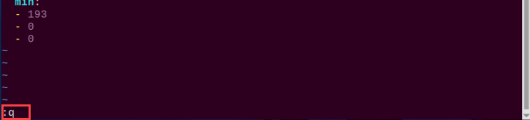
(9) You should now be able to see the purple color threshold values.

(10) Type :q and press Enter to exit this file.
(11) Then enter the command to navigate to the gameplay directory.
cd /home/ubuntu/ros2_ws/src/example/example
(12) Enter the command to open the program file and press Enter.
vim color_position_recognition.py
(13) Locate the line in the code as shown below.
(14) Press i to enter edit mode.
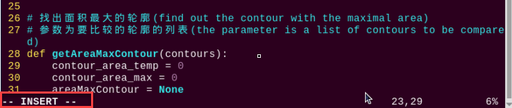
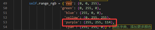
(15) Manually add the new entry “’purple’:(255, 255, 114),”. As shown in the figure below, (255, 255, 114) corresponds to the max values observed earlier.
'purple':(255, 255, 114),
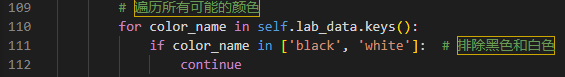
(16) Next, locate the code shown in the figure below, which will iterate through all possible colors, excluding black and white.
(17) Next to save the changes. Press the Esc key, then type the command “:wq” and press Enter to save and exit.
(18) If you want to add more colors for recognition, refer to the steps above for guidance.
4.4 Target Tracking
Note
Before getting started, please ensure that the pan-tilt servo deviation has been properly adjusted.
4.4.1 Brief Overview of Operation
In this lesson, the camera can be used to sample a color and detect the target’s position, allowing TurboPi to follow the target’s movement accordingly.
The implementation of target tracking is divided into two parts: color recognition and tracking.
In the recognition process, Gaussian filtering is first applied to reduce noise in the image. Then, the image is converted to the Lab color space to better distinguish colors.
Based on this, color thresholds are used to identify the color of the object within the circle. A mask is then applied to the image, which involves selecting parts of the image, graphics, or objects to globally or locally block out areas in the image for processing.
After masking, morphological operations including opening and closing are performed on the object image to refine the results.
Opening operation: Involves erosion followed by dilation. Effect: Removes small objects, smooths object boundaries, and does not affect object area, and helps eliminate small noise and separates connected objects.
Closing operation: Involves dilation followed by erosion. Effect: Fills small holes inside objects, connect adjacent objects, and bridge broken contours, while also smoothing boundaries without changing the area.
The tracking part uses a PID algorithm, which compares the target’s pixel coordinates in the frame with the frame’s center coordinates, reducing the distance between the two to achieve target tracking.
The PID (Proportional–Integral–Derivative) algorithm is one of the most widely used automatic control methods. It operates by adjusting control inputs based on the proportional, integral, and derivative of the error. The PID controller is popular due to its simplicity, ease of implementation, broad applicability, and independently adjustable parameters.
4.4.2 Enabling and Disabling the Feature
Note
When entering commands, be sure to use correct case and spacing. You can use the Tab key to auto-complete keywords.
(1) Power on the device and connect via VNC remote desktop tool.

(2) Click the terminal icon  in the upper-left corner of the system desktop to open a command-line window.

(3) This feature requires you to first input the command to disable the auto-start function and press Enter.
Note
After completing and closing this feature, you need to open a new red terminal window and re-enable the auto-start service. Otherwise, it may affect the operation of other functions. To re-enable the auto-start service, follow these steps: first enter ~/.stop_ros.sh, then enter ros2 launch bringup bringup.launch.py.
~/.stop_ros.sh
ros2 launch bringup bringup.launch.py
(4) Enter the following command and press Enter to start the feature.
ros2 launch app object_tracking.launch.py debug:=true
(5) Next, open a new red command-line terminal, enter the command to launch the camera for this feature, and press Enter. Once the camera is activated, click on the object you want to track in the camera’s display window, as shown in the image below.
ros2 service call /object_tracking/enter std_srvs/srv/Trigger {}
(6) In the red command-line terminal from step 5), enter the command to start pan-tilt tracking and press Enter.
ros2 service call /object_tracking/set_pan_tilt std_srvs/srv/SetBool "{data: true}"
(7) In the red command-line terminal from step 5), enter the command to start chassis tracking and press Enter.
ros2 service call /object_tracking/set_chassis_following std_srvs/srv/SetBool "{data: true}"
(8) To stop this feature, enter the command to stop pan-tilt tracking in the same terminal (step 5). Then enter the command to stop chassis tracking. Finally, enter the command to exit the tracking program. After that, go to the red terminal from step 4) and press Ctrl+C to close it. If closing fails, press Ctrl+C multiple times as needed.
ros2 service call /object_tracking/set_pan_tilt std_srvs/srv/SetBool "{data: false}"
ros2 service call /object_tracking/set_chassis_following std_srvs/srv/SetBool "{data: false}"
ros2 service call /line_following/exit std_srvs/srv/Trigger {}
4.4.3 Project Outcome
Once the program starts, the camera display will open. Click on the color you want to track in the video feed. The robot’s pan-tilt and chassis will then follow the selected color target as it moves.
Note
For best results, perform traffic sign recognition in a well-lit environment to avoid errors caused by poor lighting.
During the recognition process, avoid having objects in the camera’s field of view that are similar or identical in color to the target object, as this may cause misidentification.
4.4.4 Program Brief Analysis
The source code for this demo is located at /home/ubuntu/ros2_ws/src/app/app/tracking.py
Import the Necessary Libraries
(1) In Python, libraries are imported using the import statement. In this program, libraries such as cv2 for image processing, numpy for numerical computation, and rclpy for the ROS 2 framework are included to support image operations, mathematical calculations, and robot control.
5 6 7 8 9 10 11 12 13 14 15 16 17 18 19 20 21 22 23 24 25 26 | import os import cv2 import math import queue import rclpy import threading import numpy as np import sdk.pid as pid import sdk.common as common import sdk.yaml_handle as yaml_handle from rclpy.node import Node from app.common import Heart from cv_bridge import CvBridge from sensor_msgs.msg import Image from app.common import ColorPicker from geometry_msgs.msg import Twist from std_srvs.srv import SetBool, Trigger from interfaces.srv import SetPoint, SetFloat64 from large_models_msgs.srv import SetString from ros_robot_controller_msgs.msg import MotorsState, SetPWMServoState, PWMServoState, RGBState, RGBStates import time from rclpy.callback_groups import ReentrantCallbackGroup |
(2) Other commonly used libraries include those for OpenCV, time management, mathematics, threading, and inverse kinematics. To call a function from a library, use the format of library_name.function_name(parameter1, parameter2, …)
time.sleep(0.01)
For example, calling time.sleep() uses the sleep function from the time library, which creates a delay.
Python also includes built-in libraries such as time, cv2, and math, which can be imported and used directly. Additionally, custom libraries can be created and used. For instance, the previously mentioned “yaml_handle” file is a user-defined module for reading data.
(3) Aliasing Function Libraries
Some library names may be long or hard to remember. To simplify function calls, aliases are often used. For example:
13 | import sdk.common as common |
After aliasing, functions from the common library can be called in a format of common.function_name(parameter1, parameter2), which makes the code more convenient and easier to read.
(4) Main Function Analysis
In Python, the main function of a program is defined as “__name__ == ‘__main__:’”. The program begins by calling the init() function to perform initialization. In this case, initialization includes resetting the servo to its initial position and reading the color threshold configuration file. Other typical initialization tasks may involve setting up ports, peripherals, and timers.
After the initialization is complete and the default tracking color is set to red, enable chassis following.
677 678 679 680 681 682 683 684 685 686 687 | def main(): node = OjbectTrackingNode('object_tracking') try: rclpy.spin(node) finally: node.destroy_node() rclpy.shutdown() if __name__ == "__main__": main() |
(5) Image Processing
92 93 94 95 96 97 98 99 100 101 102 103 104 105 106 107 108 109 110 111 112 113 114 115 116 117 118 119 120 121 122 123 124 125 126 127 128 129 130 131 132 133 134 | def __call__(self, image, result_image, threshold): """Process image, detect target and return results(处理图像,检测目标并返回结果)""" h, w = image.shape[:2] image = cv2.resize(image, self.pro_size) image = cv2.cvtColor(image, cv2.COLOR_RGB2LAB) image = cv2.GaussianBlur(image, (5, 5), 5) # Determine threshold range based on manual or AI-set target color(根据手动或大模型设置的目标颜色确定阈值范围) if self.set_status == False: min_color = [int(self.target_lab[0] - 50 * threshold * 2), int(self.target_lab[1] - 50 * threshold), int(self.target_lab[2] - 50 * threshold)] max_color = [int(self.target_lab[0] + 50 * threshold * 2), int(self.target_lab[1] + 50 * threshold), int(self.target_lab[2] + 50 * threshold)] target_color = self.target_lab, min_color, max_color else: min_color = [self.lab_data[self.set_color]['min'][0], self.lab_data[self.set_color]['min'][1], self.lab_data[self.set_color]['min'][2]] max_color = [self.lab_data[self.set_color]['max'][0], self.lab_data[self.set_color]['max'][1], self.lab_data[self.set_color]['max'][2]] target_color = 0, min_color, max_color # Image processing: mask, erode, dilate, find contours(图像处理:生成掩膜、腐蚀、膨胀、轮廓检测) mask = cv2.inRange(image, tuple(target_color[1]), tuple(target_color[2])) eroded = cv2.erode(mask, cv2.getStructuringElement(cv2.MORPH_RECT, (3, 3))) dilated = cv2.dilate(eroded, cv2.getStructuringElement(cv2.MORPH_RECT, (3, 3))) contours = cv2.findContours(dilated, cv2.RETR_EXTERNAL, cv2.CHAIN_APPROX_NONE)[-2] contour_area = map(lambda c: (c, math.fabs(cv2.contourArea(c))), contours) contour_area = list(filter(lambda c: c[1] > 40, contour_area)) circle = None target_pos = None target_radius = 0 # Select target when valid contour is detected(检测到有效轮廓时,选择目标) if len(contour_area) > 0: if self.last_color_circle is None: contour, area = max(contour_area, key=lambda c_a: c_a[1]) circle = cv2.minEnclosingCircle(contour) else: (last_x, last_y), last_r = self.last_color_circle |
(6) Resize the Image for Easier Processing
95 | image = cv2.resize(image, self.pro_size) |
Parameter 1: image — the input image
The second parameter self.pro_size specifies the output image size. You can adjust this size as needed.
(7) Gaussian Blur
Images often contain noise, which can reduce clarity and make it harder to detect features. To reduce noise, different filtering methods can be applied depending on the type of noise. Common techniques include Gaussian blur, Median blur, and Mean blur.
Gaussian blur is a linear smoothing filter especially effective for reducing Gaussian noise. It’s widely used in image processing for denoising.
97 | image = cv2.GaussianBlur(image, (5, 5), 5) |
Parameter 1: image — the input image
Second parameter: (5, 5) – the size of the Gaussian kernel
Third parameter: 5 – the standard deviation in the X direction
(8) Convert the image to LAB color space, the function cv2.cvtColor() is used to convert the color space of an image.
96 | image = cv2.cvtColor(image, cv2.COLOR_RGB2LAB) |
Parameter 1: image — the input image
Second parameter: cv2.COLOR_BGR2LAB – conversion code that converts BGR format to LAB. If you want to convert from BGR to RGB instead, use cv2.COLOR_BGR2RGB.
(9) Convert images to binary images which contain only 0 and 1 values, making them simpler and easier to process.
The cv2.inRange() function is used to perform thresholding.
100 101 102 103 104 105 106 107 108 109 110 111 112 113 114 115 116 117 118 | if self.set_status == False: min_color = [int(self.target_lab[0] - 50 * threshold * 2), int(self.target_lab[1] - 50 * threshold), int(self.target_lab[2] - 50 * threshold)] max_color = [int(self.target_lab[0] + 50 * threshold * 2), int(self.target_lab[1] + 50 * threshold), int(self.target_lab[2] + 50 * threshold)] target_color = self.target_lab, min_color, max_color else: min_color = [self.lab_data[self.set_color]['min'][0], self.lab_data[self.set_color]['min'][1], self.lab_data[self.set_color]['min'][2]] max_color = [self.lab_data[self.set_color]['max'][0], self.lab_data[self.set_color]['max'][1], self.lab_data[self.set_color]['max'][2]] target_color = 0, min_color, max_color # Image processing: mask, erode, dilate, find contours(图像处理:生成掩膜、腐蚀、膨胀、轮廓检测) mask = cv2.inRange(image, tuple(target_color[1]), tuple(target_color[2])) |
Parameter 1: image — the input image
Parameter 2: min_color = [self.lab_data[self.set_color]['min'][0], self.lab_data[self.set_color]['min'][1], self.lab_data[self.set_color]['min'][2]]) defines the lower bound of the color threshold.
Parameter 3: max_color = [self.lab_data[self.set_color]['max'][0], self.lab_data[self.set_color]['max'][1], self.lab_data[self.set_color]['max'][2]] defines the upper bound of the color threshold.
(10) To reduce interference and make the image smoother, it’s necessary to perform morphological operations—erosion followed by dilation. cv2.erode() and cv2.dilate() are morphological functions.
119 120 | eroded = cv2.erode(mask, cv2.getStructuringElement(cv2.MORPH_RECT, (3, 3))) dilated = cv2.dilate(eroded, cv2.getStructuringElement(cv2.MORPH_RECT, (3, 3))) |
Parameter 1: mask — the input image.
Parameter 2: cv2.erode() — removes small noise or isolated pixels in the mask.
Parameter 3: cv2.dilate() — fills in gaps and smoothens the target contour.
Parameter 4: cv2.MORPH_RECT, (3, 3) — indicates the use of a 3x3 rectangular structuring element as the operation kernel, which determines the extent of the erosion/dilation.
(11) Obtaining Contour of Detected Object
After the above processing, contour detection is used to identify the target object. The findContours() function from the cv2 library is used.
121 | contours = cv2.findContours(dilated, cv2.RETR_EXTERNAL, cv2.CHAIN_APPROX_NONE)[-2] |
The first parameter dilated is the input image.
The second parameter cv2.RETR_EXTERNAL is the contour retrieval mode.
The third parameter cv2.CHAIN_APPROX_NONE)[-2] is the contour approximation method.
Among the obtained contours, the one with the largest area or the one closest to the previous target is prioritized for circle fitting. To avoid interference, a threshold value must be set. Only when the contour area is less than this threshold, the contour is considered valid.
129 130 131 132 133 134 135 136 137 138 139 140 | if len(contour_area) > 0: if self.last_color_circle is None: contour, area = max(contour_area, key=lambda c_a: c_a[1]) circle = cv2.minEnclosingCircle(contour) else: (last_x, last_y), last_r = self.last_color_circle circles = map(lambda c: cv2.minEnclosingCircle(c[0]), contour_area) circle_dist = list(map(lambda c: (c, math.sqrt(((c[0][0] - last_x) ** 2) + ((c[0][1] - last_y) ** 2))), circles)) circle, dist = min(circle_dist, key=lambda c: c[1]) if dist < 100: circle = circle |
(12) Obtaining Position Information
The cv2.circle function from the cv2 library is used to draw the minimum enclosing circle of the target contour. This process also obtains the center coordinates and radius of the enclosing circle.
143 144 145 146 147 148 149 150 151 152 153 154 155 156 157 158 159 160 161 162 163 164 | if circle is not None: self.lost_target_count = 0 (x, y), r = circle x = x / self.pro_size[0] * w y = y / self.pro_size[1] * h r = r / self.pro_size[0] * w target_pos = (x, y) target_radius = r self.last_color_circle = circle if self.set_status == False: result_image = cv2.circle(result_image, (int(x), int(y)), int(r), (self.target_rgb[0], self.target_rgb[1], self.target_rgb[2]), 2) else: result_image = cv2.circle(result_image, (int(x), int(y)), int(r), self.range_rgb[self.set_color], 2) else: self.lost_target_count += 1 if self.lost_target_count > 10: self.last_color_circle = None return result_image, target_pos, target_radius |
(13) Displaying the Output
316 317 318 319 320 321 | image = self.image_queue.get(block=True, timeout=0.1) result = cv2.cvtColor(image, cv2.COLOR_RGB2BGR) cv2.imshow("result", result) k = cv2.waitKey(1) if k == ord('q'): break |
The function self.image_queue() is used to acquire image data. The parameter block=True means the function will wait (block) until data is available. The parameter timeout=0.1 sets a timeout duration of 0.1 seconds, balancing response speed and resource usage.
The cv2.imshow() function displays the image in a window.
'frame' is the window name and frame_resize is the image to display. To ensure the window functions correctly, cv2.waitKey() must be included.
This function waits for a key input. The parameter 1 specifies the delay time.
Subthread Analysis
Once a color is detected, the corresponding sub-thread will control both the pan-tilt camera and robot body to track the target.
The car uses a PID algorithm to minimize the difference between the center of the camera frame and the target’s center coordinates.
The PID (Proportional–Integral–Derivative) algorithm is one of the most widely used automatic control methods. It operates by adjusting control inputs based on the proportional, integral, and derivative of the error.
(1) Pan-tilt Tracking
407 408 409 410 411 412 413 414 415 416 | if self.pan_tilt_enabled and not self.chassis_following_enabled: # Pan-tilt-only tracking(单独云台追踪) if target_pos: x, y = target_pos servo_x, servo_y, _, _ = self.tracker.update_pid(x, y, self.image_width, self.image_height) self.publish_servo(servo_x, servo_y) self.last_target_time = time.time() else: self.handle_target_lost_pan_tilt() if time.time() - self.last_target_time > 5 and self.exit_funcation: |
The function self.tracker.update_pid() is used to control the PWM servo. For example, in the code servo_x, servo_y = self.tracker.update_pid(x, y, self.image_width, self.image_height):
The first parameterservo_x, servo_y represents the control values for the pan-tilt servo, calculated using the PID algorithm.
The second parameter self.image_width, self.image_height indicates the width and height of the image.
(2) Chassis Tracking
420 421 422 423 424 425 426 427 428 429 430 431 432 433 434 | elif self.chassis_following_enabled and not self.pan_tilt_enabled: # Chassis-only tracking(单独车体追踪) if target_pos: x, y = target_pos self.control_chassis(x, y, 1500, target_radius) self.publish_servo(1500, 1600) self.last_target_time = time.time() else: self.handle_target_lost_chassis() if time.time() - self.last_target_time > 5 and self.exit_funcation: self.get_logger().info("5秒未检测到目标,自动退出") self.exit_funcation = False self.exit_srv_callback(Trigger.Request(), Trigger.Response()) elif self.pan_tilt_enabled and self.chassis_following_enabled: # Pan-tilt + chassis joint tracking: use pan-tilt PID output for chassis control(云台+车体联合追踪:云台PID输出控制小车运动) |
For chassis tracking, take the code self.control_chassis(x, y, 1500, target_radius) as an example. The meaning of the parameters inside the parentheses is as follows:
The first parameter x, y refers to the coordinates of the tracked object.
The second parameter 1500 refers to the preset servo position.
The third parameter target_radius refers to the radius of the tracked object.
4.5 Visual Line Following
Note
Before getting started, please ensure that the pan-tilt servo deviation has been properly adjusted.
4.5.1 Brief Overview of Operation
In this lesson, the camera can recognize black lines, allowing TurboPi to follow the line autonomously.
The intelligent line-following feature consists of two parts: color recognition and line-following movement.
In the recognition process, Gaussian filtering is first applied to reduce noise in the image. Then, the color of the line is converted using the Lab color space.
Based on this, color thresholds are used to identify the color of the object within the bounding box. A mask is then applied to the image, which involves selecting parts of the image, graphics, or objects to globally or locally block out areas in the image for processing.
Then, after performing morphological opening and closing operations on the object image, the largest contour is highlighted with a bounding box, and the center point of the line is marked with a dot.
Opening operation: Involves erosion followed by dilation. Effect: Removes small objects, smooths object boundaries, and does not affect object area, and helps eliminate small noise and separates connected objects.
Closing operation: Involves dilation followed by erosion. Effect: Fills small holes inside objects, connect adjacent objects, and bridge broken contours, while also smoothing boundaries without changing the area.
When the black line is detected, the PID algorithm compares the center coordinates of the camera image with the actual coordinates of the black line. Based on this comparison, it drives the motor to make TurboPi follow the recognized black line.
The PID (Proportional–Integral–Derivative) algorithm is one of the most widely used automatic control methods. It operates by adjusting control inputs based on the proportional, integral, and derivative of the error. The PID controller is popular due to its simplicity, ease of implementation, broad applicability, and independently adjustable parameters.
4.5.2 Enabling and Disabling the Feature
Note
When entering commands, be sure to use correct case and spacing. You can use the Tab key to auto-complete keywords.
(1) Power on the robot and connect via VNC remote desktop tool.

(2) Click the terminal icon  in the upper-left corner of the system desktop to open a command-line window.

(3) This feature requires you to first input the command to disable the auto-start function, then enter the command and press Enter. Note: After completing and closing this feature, you need to open a new red terminal window and re-enable the auto-start service. Otherwise, it may affect the operation of other functions. To re-enable the auto-start service, follow these steps: first enter ~/.stop_ros.sh, then enter ros2 launch bringup bringup.launch.py.
~/.stop_ros.sh
(4) Enter the following command and press Enter to start the feature.
ros2 launch app line_following.launch.py debug:=true
(5) Next, enter the command to launch the camera for this feature, and press Enter. Once the camera is activated, click on the object you want to track in the camera’s display window, as shown in the image below.
ros2 service call /line_following/enter std_srvs/srv/Trigger {}
(6) Enter the following command to start the feature, and the robot will follow the black line when you press Enter.
ros2 service call /line_following/set_running std_srvs/srv/SetBool "{data: True}"
(7) To close this program, first enter the command to stop the line-following feature in the red terminal at step 5), then enter the command to exit the line-following feature. Finally, press Ctrl + C in the red terminal at step 4). If it fails to close, press Ctrl + C multiple times. Execute the following commands one by one in sequence.
ros2 service call /line_following/set_running std_srvs/srv/SetBool "{data: false}"
ros2 service call /line_following/exit std_srvs/srv/Trigger {}
4.5.3 Project Outcome
By default, the TurboPi program recognizes the color black. After starting the feature, TurboPi will follow the black line.
You can use black electrical tape about 3 cm wide to create the map for this feature. Reference as the figure below:

4.5.4 Program Brief Analysis
The source code for this demo is located at /home/ubuntu/ros2 ws/src/app/app/line_following.py
Import Libraries
In Python, libraries are imported using the import statement. In this program, libraries such as cv2 for image processing, numpy for numerical computation, and rclpy for the ROS 2 framework are included to support image operations, mathematical calculations, and robot control.
4 5 6 7 8 9 10 11 12 13 14 15 16 17 18 19 20 21 22 23 24 25 | import os import cv2 import math import time import rclpy import queue import threading import numpy as np import sdk.pid as pid import sdk.common as common import sdk.yaml_handle as yaml_handle from rclpy.node import Node from app.common import Heart,ColorPicker from cv_bridge import CvBridge from geometry_msgs.msg import Twist from std_msgs.msg import Int32 from std_srvs.srv import SetBool, Trigger from sensor_msgs.msg import Image from interfaces.srv import SetPoint, SetFloat64 from rclpy.qos import QoSProfile, QoSReliabilityPolicy from large_models_msgs.srv import SetString from ros_robot_controller_msgs.msg import MotorsState, SetPWMServoState, PWMServoState,RGBState,RGBStates |
Main Function Analysis
Initialization and Instantiation
439 440 441 442 443 444 445 446 447 448 | def main(): node = LineFollowingNode('line_following') try: rclpy.spin(node) finally: node.destroy_node() rclpy.shutdown() if __name__ == "__main__": main() |
(1) The init() function is called to initialize the TurboPi system.
107 108 109 110 | class LineFollowingNode(Node): def __init__(self, name): rclpy.init() super().__init__(name, allow_undeclared_parameters=True, automatically_declare_parameters_from_overrides=True) |
The get_yaml_data method reads the YAML file pointed to by servo_file_path and parses the data, such as servo angle ranges, initial positions, control parameters, etc. The parsed YAML data is then assigned to an instance variable of the class “self.servo_data” for use in subsequent code, such as initializing servos, configuring motion parameters, etc.
137 | self.servo_data = yaml_handle.get_yaml_data(yaml_handle.servo_file_path) |
(2) The target color for line following is selected via mouse click color picking.
183 184 185 186 187 188 189 190 191 192 193 194 195 196 197 198 199 200 201 202 203 204 205 206 207 208 209 | def main(self): while True: try: image = self.image_queue.get(block=True, timeout=1) except queue.Empty: continue result = cv2.cvtColor(image, cv2.COLOR_RGB2BGR) cv2.imshow("result", result) if self.debug and not self.set_callback: self.set_callback = True # Set a callback function for mouse click event(设置鼠标点击事件的回调函数) cv2.setMouseCallback("result", self.mouse_callback) k = cv2.waitKey(1) if k != -1: break self.mecanum_pub.publish(Twist()) rclpy.shutdown() def mouse_callback(self, event, x, y, flags, param): if event == cv2.EVENT_LBUTTONDOWN: self.get_logger().info("x:{} y{}".format(x, y)) msg = SetPoint.Request() if self.image_height is not None and self.image_width is not None: msg.data.x = x / self.image_width msg.data.y = y / self.image_height self.set_target_color_srv_callback(msg, SetPoint.Response()) |
A loop is used to continuously acquire, display, and interact with image data in real-time, integrating keyboard event handling and robot motion command publishing.
310 311 312 313 314 315 316 317 318 319 | def set_large_model_target_color_srv_callback(self, request, response): self.get_logger().info('\033[1;32m%s\033[0m' % "set_large_model_target_color") with self.lock: self.__target_color = request.data self.set_model = True self.mecanum_pub.publish(Twist()) self.no_target_time = 0 self.exit_funcation = True response.success = True return response |
The set_target_color_srv_callback() service interface implements the target color setting functionality, including status reset, color picker control, and thread-safe operations. This function is a key logic component for the robot’s color interaction capabilities.
(3) The set_running_srv_callback() function is called to start the intelligent line-following feature.
332 333 334 335 336 337 338 339 340 341 342 343 | # Start feature (开启玩法) def set_running_srv_callback(self, request, response): self.get_logger().info('\033[1;32m%s\033[0m' % "set_running") with self.lock: self.is_running = request.data if not self.is_running: self.mecanum_pub.publish(Twist()) if self.is_running: self.no_target_time = 0 response.success = True response.message = "set_running" return response |
(4) Image Processing
The image_callback() function handles image preprocessing, laying the groundwork for later target detection and image annotation.
367 368 369 370 371 372 | def image_callback(self, ros_image): cv_image = self.bridge.imgmsg_to_cv2(ros_image, "rgb8") rgb_image = np.array(cv_image, dtype=np.uint8) self.image_height, self.image_width = rgb_image.shape[:2] result_image = np.copy(rgb_image) # The image used to display the result(显示结果用的画面) target_detected = False # Flag indicating whether the target is detected (标志是否检测到目标) |
(5) Gaussian Blur
Images often contain noise, which can reduce clarity and make it harder to detect features. To reduce noise, different filtering methods can be applied depending on the type of noise. Common techniques include Gaussian blur, Median blur, and Mean blur.
Gaussian blur is a linear smoothing filter especially effective for reducing Gaussian noise. It’s widely used in image processing for denoising.
79 | img_blur = cv2.GaussianBlur(img_lab, (3, 3), 3) # Perform Gaussian filtering to reduce noise(高斯模糊去噪) |
Parameter 1: img_lab — the input image
Second parameter: (3, 3) – the size of the Gaussian kernel
Third parameter: 3 – the standard deviation in the X direction
From the original image, extract the image region defined by the coordinate ratio values roi[0]*h, roi[1]*h, roi[2]*w, and roi[3]*w, and assign the cropped result to the variable blob.
77 | blob = image[int(roi[0]*h):int(roi[1]*h), int(roi[2]*w):int(roi[3]*w)] # Intercept roi(截取roi) |
Then, use the cvtColor() function from the cv2 library to convert the BGR image to the LAB color space.
78 | img_lab = cv2.cvtColor(blob, cv2.COLOR_RGB2LAB) # Convert rgb into lab(rgb转lab) |
Parameter 1: blobs — the input image
The second parameter, cv2.COLOR_BGR2RGB, specifies the conversion type, converting BGR image to LAB color space.
The inRange() function from the cv2 library is used to perform thresholding.
80 | mask = cv2.inRange(img_blur, tuple(target_color[1]), tuple(target_color[2])) # Image binarization(二值化) |
Parameter 1: img_blur — the input image.
Parameter 2: tuple(target_color[1]) — the lower threshold value.
Parameter 3: tuple(target_color[2]) — the upper threshold value.
To reduce interference and make the image smoother, it’s necessary to perform morphological operations such as erosion and dilation.
81 82 | eroded = cv2.erode(mask, cv2.getStructuringElement(cv2.MORPH_RECT, (3, 3))) # Corrode(腐蚀) dilated = cv2.dilate(eroded, cv2.getStructuringElement(cv2.MORPH_RECT, (3, 3))) # Dilate(膨胀) |
The erode() function is used to perform erosion on the image.
For example, in the code eroded = cv2.erode(frame_mask, cv2.getStructuringElement(cv2.MORPH_RECT, (3, 3)), the parameters mean:
Parameter 1: mask — the input image.
Parameter 2: cv2.getStructuringElement(cv2.MORPH_RECT, (3, 3)) defines the structuring element or kernel used for the operation. The first value in the parentheses specifies the kernel shape, and the second specifies the kernel size.
The dilate() function is used to perform dilation on the image. The parameters inside the parentheses are the same as those used in the erode() function.
After the above processing, contour detection is used to identify the target object. The findContours() function from the cv2 library is used.
84 | contours = cv2.findContours(dilated, cv2.RETR_EXTERNAL, cv2.CHAIN_APPROX_TC89_L1)[-2] # Find the contour(找轮廓) |
The first parameter dilated is the input image.
The second parameter cv2.RETR_EXTERNAL is the contour retrieval mode.
The third parameter cv2.CHAIN_APPROX_NONE)[-2] is the contour approximation method.
Among the obtained contours, the largest one is selected by area, and rectangles are drawn for the top, middle, and bottom parts
85 86 87 88 89 90 91 | max_contour_area = self.get_area_max_contour(contours, 30) # Get the contour corresponding to the largest contour(获取最大面积对应轮廓) if max_contour_area is not None: rect = cv2.minAreaRect(max_contour_area[0]) # Minimum circumscribed rectangle(最小外接矩形) box = np.intp(cv2.boxPoints(rect)) # Four corners(四个角) for j in range(4): box[j, 1] = box[j, 1] + int(roi[0]*h) cv2.drawContours(result_image, [box], -1, (0, 255, 255), 2) # Draw the rectangle composed of four points(画出四个点组成的矩形) |
The center points of these three rectangles are calculated and marked. The line_center_x variable is used to determine the degree of deviation of TurboPi**.**
93 94 95 96 97 98 99 100 101 102 103 104 105 | # Acquire the diagonal points of the rectangle(获取矩形对角点) pt1_x, pt1_y = box[0, 0], box[0, 1] pt3_x, pt3_y = box[2, 0], box[2, 1] # Center point of the line(线的中心点) line_center_x, line_center_y = (pt1_x + pt3_x) / 2, (pt1_y + pt3_y) / 2 cv2.circle(result_image, (int(line_center_x), int(line_center_y)), 5, (0, 0, 255), -1) # Draw the center point(画出中心点) centroid_sum += line_center_x * roi[-1] if centroid_sum == 0: return result_image, None center_pos = centroid_sum / self.weight_sum # Calculate the center point according to the ratio(按比重计算中心点) deflection_angle = -math.atan((center_pos - (w / 2.0)) / (h / 2.0)) # Calculate the line angle(计算线角度) return result_image, deflection_angle |
(6) Displaying the Output
The image_callback() function from the cv2 library is called to scale the image and display it in real-time in the return image feed.
367 368 369 370 371 372 | def image_callback(self, ros_image): cv_image = self.bridge.imgmsg_to_cv2(ros_image, "rgb8") rgb_image = np.array(cv_image, dtype=np.uint8) self.image_height, self.image_width = rgb_image.shape[:2] result_image = np.copy(rgb_image) # The image used to display the result(显示结果用的画面) target_detected = False # Flag indicating whether the target is detected (标志是否检测到目标) |
4.6 QR Code Recognition
4.6.1 Brief Overview of Operation
In this lesson, the camera can recognize QR codes and instruct TurboPi to move based on the recognized code. QR code images are located in the “QR Code Images” folder in the same directory as this document. For recognition, you can send the images to your phone or print them out. Recommended print size is 5×5 cm.
A QR code is a black-and-white pattern arranged in a specific geometric format on a 2D plane to encode data symbols.
It cleverly uses the concept of binary bit streams (”0” and “1”), which form the basis of computer logic, and represents textual or numerical information using a variety of geometric shapes corresponding to binary. These codes can be automatically scanned using image input devices or photoelectric scanners for automated data processing.
QR codes share some common features with barcode technology. Each encoding system has its own character set, each character occupies a specific width, and they have built-in error-checking capabilities, among other characteristics.
In this lesson, we use pre-generated QR code models. The camera captures the QR code image and processes it.
Next, the QR code is detected and its information extracted.
Finally, the recognized QR code is highlighted with a frame, and the robot executes a corresponding action.
4.6.2 Enabling and Disabling the Feature
Note
When entering commands, be sure to use correct case and spacing. You can use the Tab key to auto-complete keywords.
(1) Power on the device and connect via VNC remote desktop tool.

(2) Click the terminal icon  in the upper-left corner of the system desktop to open a command-line window.

(3) Entering the following command and press Enter to start the feature.
ros2 service call /qrcode/enter std_srvs/srv/Trigger {}
(4) Enter the following command and press Enter.
ros2 service call /qrcode/set_running std_srvs/srv/SetBool data:\ ture
(5) Open another terminal and launch the visualization interface. Select “/qrcode/image_result”.
rqt
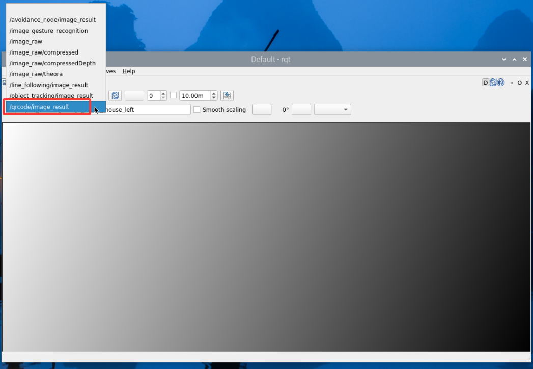
(6) To close this program, first enter the command to stop the feature in the red terminal at step 4), then enter the command to exit the feature. Finally, press Ctrl + C in the red terminal at step 5). If it fails to close, press Ctrl + C multiple times. Execute the following commands one by one in sequence.
ros2 service call /qrcode/set_running std_srvs/srv/SetBool data:\ false
ros2 service call /qrcode/exit std_srvs/srv/Trigger {}
4.6.3 Project Outcome
After the feature is activated, when the camera detects a QR code, it will highlight the QR code in the feedback display and show the recognition result in the bottom-left corner of the screen. The robot will then move accordingly. Note: directions such as forward, backward, left, and right are based on TurboPi’s first-person perspective.
| QR Code ID | Action |
|---|---|
| 1 | TurboPi moves forward a certain distance |
| 2 | TurboPi moves backward a certain distance |
| 3 | TurboPi moves right a certain distance |
| 4 | TurboPi moves left a certain distance |
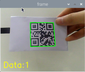
4.6.4 Program Brief Analysis
The source code for this demo is located at /home/ubuntu/ros2_ws/src/app/app/qrcode.py
Import Libraries
5 6 7 8 9 10 11 12 13 14 15 16 17 18 19 20 | import os import cv2 import queue import rclpy import threading import numpy as np import time from rclpy.node import Node from cv_bridge import CvBridge from sensor_msgs.msg import Image from pyzbar import pyzbar from geometry_msgs.msg import Twist from std_srvs.srv import SetBool, Trigger from rclpy.callback_groups import ReentrantCallbackGroup from app.common import Heart from ros_robot_controller_msgs.msg import SetPWMServoState, PWMServoState |
In Python, libraries are imported using the import statement. In this program, libraries such as cv2 for image processing, numpy for numerical computation, and rclpy for the ROS 2 framework are included to support image operations, mathematical calculations, and robot control.
Parameter Declaration and Attribute Initialization
23 24 25 26 27 28 29 30 31 32 33 34 35 36 37 38 39 40 41 42 43 44 | class QRCodeDetectNode(Node): def __init__(self, name): super().__init__(name) self.declare_parameter('debug', False) self.name = name self.is_running = False self.bridge = CvBridge() self.lock = threading.RLock() self.image_sub = None self.result_image = None self.image_height = None self.image_width = None self.image_queue = queue.Queue(2) self.exit_allowed = True # Add flag to allow execution of exit_srv_callback (添加标志位,允许执行 exit_srv_callback) self.heart = None # Heartbeat object (心跳包对象) # self._timers = [] # Remove timer from list (移除定时器列表) threading.Thread(target=self.main, daemon=True).start() self.debug = self.get_parameter('debug').value callback_group = ReentrantCallbackGroup() |
Used for handling the QR code detection function, including setting debug parameters, enabling or disabling QR code recognition, initializing image conversion tools, and data locks. These components lay the groundwork for executing QR code detection tasks.
Main Function Analysis
(1) Initialization and Instantiation
① In Python, the main function of a program is defined as __name__ == '__main__:'.
276 277 278 279 280 281 282 283 284 285 | def main(): rclpy.init() # Initialization (初始化) node = QRCodeDetectNode('qrcode') rclpy.spin(node) node.destroy_node() rclpy.shutdown() if __name__ == "__main__": main() |
② Servo Position Control Function
179 180 181 182 183 184 185 186 187 188 189 190 | def set_servo_position(self, servo_id, position, duration=0.0): """Publish servo control message with duration (发布舵机控制消息,加入持续时间) """ servo_state = PWMServoState() servo_state.id = [servo_id] servo_state.position = [position] set_pwm_servo_state_msg = SetPWMServoState() set_pwm_servo_state_msg.state = [servo_state] set_pwm_servo_state_msg.duration = duration self.pwm_servo_pub.publish(set_pwm_servo_state_msg) self.get_logger().info( f"Set servo {servo_id} position to {position} with duration {duration} seconds") |
Parameter 1: servo_id — The ID number of the servo to control.
Parameter 2: position — The target position to move the servo to.
Parameter 3: duration — The duration of the movement in seconds, default is 0.0 seconds.
By creating instances of different classes and properly configuring their attributes, information such as servo ID, position, and movement duration is packaged into a standardized control message format, enabling precise servo control. Message publishing ensures that control commands are delivered to the servo, while logging enhances the maintainability and traceability of the program, making it easier to quickly identify and resolve issues when they arise.
③ This function also handles entering and exiting QR code detection mode, manages servo position, and controls camera subscription tasks.
107 108 109 110 111 112 113 114 115 | def exit_srv_callback(self, request, response): self.get_logger().info('\033[1;32m%s\033[0m' % 'QRCode exit') with self.lock: if not self.exit_allowed: # Check if execution is allowed (检查是否允许执行) self.get_logger().info("exit_srv_callback blocked by flag.") response.success = True response.message = "exit blocked" return response |
Parameter 1: self.get_logger().info('033[1;32m%s033[0m' % 'QRCode detect enter') logs a message indicating entry into the QR code detection process. The \033[1;32m and \033[0m are used to color the log output green.
Parameter 2: self.set_servo_position(1, 1500, 2.0) sets servo ID 1 to position 1500 with a movement duration of 2.0 seconds.
(2) QR Code Image Processing
start_recognition_srv_callback() function: Used to enable or disable QR code recognition.
150 151 152 153 154 155 156 157 158 159 160 161 162 | def start_recognition_srv_callback(self, request, response): """Service: Start/stop QR code recognition (服务:开启/停止二维码识别) """ with self.lock: self.is_running = request.data # Start or stop QR code recognition (启动或停止二维码识别) if self.is_running: self.get_logger().info("二维码识别已启动") else: self.get_logger().info("二维码识别已停止") self.mecanum_pub.publish(Twist()) # Stop robot motion control (停止控制机器人运动) response.success = True response.message = "Start recognition" if self.is_running else "Stop recognition" return response |
set_running_srv_callback() function: Starts or stops the QR code detection process.
164 165 166 167 168 169 170 171 172 173 174 175 176 177 | def set_running_srv_callback(self, request, response): self.get_logger().info('\033[1;32m%s\033[0m' % 'set running') with self.lock: self.is_running = request.data # Enable or disable recognition (启用或停止识别) if self.is_running: self.get_logger().info("二维码识别已启动") else: self.get_logger().info("二维码识别已停止") self.mecanum_pub.publish(Twist()) # Stop robot motion control (停止控制机器人运动) response.success = True response.message = "set running" return response |
(3) Once a QR code is detected, a bounding box is drawn around it and the decoded information is printed on the screen.
210 211 212 213 214 | cv2.polylines(result_image, [np.int32(hull)], isClosed=True, color=(0, 255, 0), thickness=3) cv2.putText(result_image, obj.data.decode("utf-8"), (obj.rect[0], obj.rect[1]), cv2.FONT_HERSHEY_SIMPLEX, 0.5, (0, 0, 255), 2) |
Use cv2.polylines() function from cv2 library to draw a bounding polygon around the detected QR code. Example: cv2.polylines(result_image, [np.int32(hull)], isClosed=True, color=(0, 255, 0), thickness=3)
Parameter 1: result_image — The image where the detected QR code is outlined.
Parameter 2: [np.int32(hull)] — Refers to the vertex coordinates of the polygon to be drawn.
Parameter 3: isClosed=True — Indicates that the polygon should be a closed shape; if set to False, it will draw an open polyline.
Parameter 4: (0, 255, 0) — Line color of the polygon.
Parameter 5: 3 — Line thickness of the polygon.
Use cv2.putText() from cv2 library to print the decoded QR code data on the image.
(4) Displaying the Output
Use imgmsg_to_cv2() from the cv2 library to convert ROS image messages into OpenCV format, allowing for easier manipulation and display of image data.
192 193 194 195 | def image_callback(self, ros_image): cv_image = self.bridge.imgmsg_to_cv2(ros_image, "rgb8") rgb_image = np.array(cv_image, dtype=np.uint8) self.image_height, self.image_width = rgb_image.shape[:2] |
Subthread Analysis
A sub-thread runs the control_robot_based_on_qr() function to control the movement duration of the mecanum-wheeled robot.
226 227 228 229 230 231 232 233 234 235 | def control_robot_based_on_qr(self, qr_data): if qr_data == "1": # Move forward for 2 seconds using time.sleep (前进2秒,使用 time.sleep) self.move_forward(2) elif qr_data == "2": self.move_backward(2) elif qr_data == "3": self.move_right(2) elif qr_data == "4": self.move_left(2) |
Inside the control_robot_based_on_qr() function, the motor is controlled based on the recognized QR code information.
237 238 239 240 241 242 243 244 245 246 247 248 249 250 251 252 253 254 255 256 257 258 259 260 261 262 263 264 265 266 267 268 269 270 271 272 273 | def move_forward(self, duration): twist = Twist() twist.linear.x = 0.6 # Forward speed (前进速度) self.mecanum_pub.publish(twist) self.get_logger().info(f"Moving forward for {duration} seconds") time.sleep(duration) self.stop_robot() def move_backward(self, duration): twist = Twist() twist.linear.x = -0.6 # Backward speed (后退速度) self.mecanum_pub.publish(twist) self.get_logger().info(f"Moving backward for {duration} seconds") time.sleep(duration) self.stop_robot() def move_right(self, duration): twist = Twist() twist.linear.y = -0.6 # Right translation speed (右平移速度) self.mecanum_pub.publish(twist) self.get_logger().info(f"Moving right for {duration} seconds") time.sleep(duration) self.stop_robot() def move_left(self, duration): twist = Twist() twist.linear.y = 0.6 # Left translation speed (左平移速度) self.mecanum_pub.publish(twist) self.get_logger().info(f"Moving left for {duration} seconds") time.sleep(duration) self.stop_robot() def stop_robot(self): """Stop robot motion (停止机器人的运动) """ twist = Twist() self.mecanum_pub.publish(twist) self.get_logger().info("Robot stopped") |
For example, in the robot motion control code using twist.linear.x and twist.linear.y, the meanings of the parameters inside the parentheses are as follows:
The first parameter, twist.linear.x, represents the robot’s linear velocity along the x-axis, controlling forward and backward movement. A positive value means moving forward, a negative value means moving backward, and the value range is from -1 to 1.
The second parameter, twist.linear.y, represents the robot’s linear velocity along the y-axis, controlling left and right movement. A positive value means moving right, a negative value means moving left, and the value range is from -1 to 1.
4.7 Intelligent Obstacle Avoidance
4.7.1 Brief Overview of Operation
In this lesson, the robot uses an ultrasonic sensor to detect obstacles. When an obstacle is detected, the robot will automatically avoid it.
We are using a glowy ultrasonic distance measurement module, which integrates an ultrasonic transmitter circuit, receiver circuit, and digital processing unit within the same chip. This module uses an IIC communication interface and can read distance measurements from the ultrasonic sensor via IIC.
It features two probes—one for transmitting ultrasonic waves and the other for receiving them.
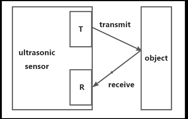
How it works: During distance measurement, the module automatically sends out 8 pulses of 40 kHz square waves and waits for a signal to return. If a signal is returned, the module outputs a high-level signal, and the duration of the high-level signal corresponds to the time it takes for the ultrasound to travel to the object and back.
The formula used to calculate distance is: Distance = (High-level time × Speed of sound (340 m/s)) / 2.
When the intelligent obstacle avoidance mode is activated, the ultrasonic sensor continuously measures the distance between the robot and objects ahead. The robot’s movement is then controlled based on the measurement. If the distance is greater than the preset threshold, the robot moves forward. If the distance is less than the preset threshold, the robot stops and turns to avoid the obstacle.
4.7.2 Enabling and Disabling the Feature
Note
When entering commands, be sure to use correct case and spacing. You can use the Tab key to auto-complete keywords.
(1) Power on the robot and connect via VNC remote desktop tool.

(2) Click the terminal icon  in the upper-left corner of the system desktop to open a command-line window.
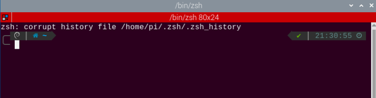
(3) In the opened interface, enter the command and press Enter to start the feature.
ros2 service call /avoidance_node/enter std_srvs/srv/Trigger {}
(4) Enter the command with obstacle avoidance parameters, then press Enter to run the obstacle avoidance program.
Example: Obstacle avoidance threshold: 30 cm. Speed: 40
ros2 service call /avoidance_node/set_param interfaces/srv/SetFloat64List "{data: [30, 40]}"
(5) Enter the following command and press Enter to enable the obstacle avoidance feature.
ros2 service call /avoidance_node/set_running std_srvs/srv/SetBool "{data: true}"
(6) To stop the program, first run the command to disable the obstacle avoidance feature, then run the command to exit the obstacle avoidance feature. Execute the following commands one by one in sequence.
ros2 service call /avoidance_node/set_running std_srvs/srv/SetBool "{data: false}"
ros2 service call /avoidance_node/exit std_srvs/srv/Trigger {}
4.7.3 Project Outcome
Once the feature is activated, the return screen will display the distance between the robot and the detected object. When the distance is less than or equal to 30 cm, the robot will turn left. When the distance is greater than 30 cm, the robot will continue to move forward.
4.7.4 Program Brief Analysis
The source code for this program is located at: /home/ubuntu/ros2_ws/src/app/app/avoidance_node.py
Import Libraries
7 8 9 10 11 12 13 14 15 16 17 18 19 20 21 22 23 24 25 26 27 28 | import math import time import queue import rclpy import signal import threading import numpy as np import pandas as pd import cv2 from app.common import Heart from rclpy.node import Node from std_srvs.srv import Trigger from geometry_msgs.msg import Twist from std_msgs.msg import Int32 from cv_bridge import CvBridge from sensor_msgs.msg import Image from std_srvs.srv import SetBool, Trigger from std_msgs.msg import UInt16, Bool from interfaces.srv import SetInt64, SetFloat64List from sdk.sonar import Sonar from ros_robot_controller_msgs.msg import RGBState,RGBStates |
In Python, libraries are imported using the import statement. In this program, libraries such as cv2 for image processing, numpy for numerical computation, and rclpy for the ROS 2 framework are included to support image operations, mathematical calculations, and robot control.
(2) Define Instance Variables for the Class
35 36 37 38 39 40 41 42 43 44 45 46 47 48 49 50 51 52 53 54 55 | self.sonar = Sonar() self.running = True self.heart = None # Heartbeat object (心跳包对象) self.name = name self.image_sub = None self.sonar_sub = None self.threshold = 30 # Centimeters (厘米) self.speed = 0.4 self.distance = 500 self.distance_data = [] self.bridge = CvBridge() self.is_running = False self.turn = True self.forward = True self.stopMotor = True self.lock = threading.RLock() self.result_publisher = self.create_publisher(Image, '~/image_result', 1) # Publish the image processing result(图像处理结果发布) self.mecanum_pub = self.create_publisher(Twist, 'cmd_vel', 1) # Chassis control(底盘控制) self.sonar_rgb_pub = self.create_publisher(RGBStates, 'sonar_controller/set_rgb', 10) |
Initialize the obstacle avoidance node with its “basic equipment”: set key parameters such as the obstacle distance threshold and movement speed, create storage for distance data, prepare tools for image format conversion, and define flags to track node status, turning status, and motor status. A thread lock is also set up to ensure data safety during multitasking. These preparations enable the node to smoothly perform core functions such as obstacle avoidance, image data processing, and motion control.
(3) Main Function Analysis
① Initialization and Instantiation
242 243 244 245 246 247 248 249 250 251 252 253 254 255 256 257 | def main(): node = AvoidanceNode('avoidance_node') try: rclpy.spin(node) except KeyboardInterrupt: node.destroy_node() node.sonar.setPixelColor(0, (0, 0, 0)) node.sonar.setPixelColor(1, (0, 0, 0)) rclpy.shutdown() print('shutdown') finally: node.destroy_node() print('shutdown finish') if __name__ == '__main__': main() |
② The init() function is called to initialize the TurboPi system.
33 34 35 36 | rclpy.init() super().__init__(name, allow_undeclared_parameters=True, automatically_declare_parameters_from_overrides=True) self.sonar = Sonar() self.running = True |
③ And the reset_value() function resets the servo and motor-related parameters.
69 70 71 72 73 74 75 76 77 78 79 80 | def get_node_state(self, request, response): response.success = True return response def reset_value(self,): self.threshold = 30 self.speed = 0.4 self.distance = 500 self.stopMotor = True self.is_running = False self.forward = True self.turn = True |
(4) Sensor Detection Processing
① The distance() function is used to retrieve the detection value from the ultrasonic sensor and store it in the data list.
217 218 219 220 | dist = self.distance / 10.0 # Get ultrasonic sensor distance data(获取超声波传感器距离数据) self.distance_data.append(dist) # Cache distance data into a list(距离数据缓存到列表) data = pd.DataFrame(self.distance_data) data_ = data.copy() |
② To prevent false detection, the system takes the average of five readings to determine whether an obstacle is present.
224 225 226 227 | data_c = data[np.abs(data - u) <= std] distance = data_c.mean()[0] if len(self.distance_data) == 5: # Take the average of multiple detections(多次检测取平均值) self.distance_data.remove(self.distance_data[0]) |
③ Then, the putText() function from the cv2 library is called to display the measured distance from the ultrasonic sensor on the screen.
231 | result_image = cv2.putText(result_image, "Dist:%.1fcm"%distance, (30, 480-30), cv2.FONT_HERSHEY_SIMPLEX, 1.2, (255, 255, 0), 2) |
Subthread Analysis
A subthread is started to call the distance_callback() function, which controls obstacle avoidance for TurboPi.
184 185 | def distance_callback(self,msg): self.distance = msg.data |
(1) Within the distance_callback() function, the speed of TurboPi is adjusted based on whether the detected distance reaches the threshold.
187 188 189 190 191 192 193 194 195 196 197 198 199 200 201 202 203 204 205 206 207 208 209 | twist = Twist() if self.is_running: if self.distance / 10.0 <= self.threshold: # Check if distance threshold is reached(检测是否达到距离阈值) twist.angular.z = 11.0 if self.turn: # Implement a check to prevent duplicate commands(做一个判断防止重复发指令) self.turn = False self.forward = True self.stopMotor = True else: twist.linear.x = float(self.speed) twist.angular.z = 0.0 if self.forward: # Implement a check to prevent duplicate commands(做一个判断防止重复发指令) self.turn = True self.forward = False self.stopMotor = True self.mecanum_pub.publish(twist) else: if self.stopMotor: # Implement a check to prevent duplicate commands(做一个判断防止重复发指令) self.stopMotor = False self.turn = True self.forward = True #self.mecanum_pub.publish(Twist()) |
For example, motor control is handled by the following code:
if self.distance / 10.0 <= self.threshold:

twist.angular.z = 7.0

if self.turn:

self.turn = False

self.forward = True

self.stopMotor = True. The meaning of each part is as follows:
Parameter 1 if self.distance / 10.0 <= self.threshold: compares the detected distance with the preset threshold. If the object is too close, it sets the angular speed (twist.angular.z = 7.0) to make the robot rotate.
Parameter 2 if self.turn: if True, updates the flags to self.turn = False, self.forward = True, and self.stopMotor = True. These flags help prevent repeated turn commands and ensure a single, clear control logic.
(2) The ultrasonic sensor’s reading is then used to determine if there’s an obstacle. If no obstacle is detected, the robot moves forward. If an obstacle is detected, the robot turns to avoid it.
187 188 189 190 191 192 193 194 195 196 197 198 199 200 201 202 203 204 205 206 207 208 209 | twist = Twist() if self.is_running: if self.distance / 10.0 <= self.threshold: # Check if distance threshold is reached(检测是否达到距离阈值) twist.angular.z = 11.0 if self.turn: # Implement a check to prevent duplicate commands(做一个判断防止重复发指令) self.turn = False self.forward = True self.stopMotor = True else: twist.linear.x = float(self.speed) twist.angular.z = 0.0 if self.forward: # Implement a check to prevent duplicate commands(做一个判断防止重复发指令) self.turn = True self.forward = False self.stopMotor = True self.mecanum_pub.publish(twist) else: if self.stopMotor: # Implement a check to prevent duplicate commands(做一个判断防止重复发指令) self.stopMotor = False self.turn = True self.forward = True #self.mecanum_pub.publish(Twist()) |
4.7.5 Feature Extensions
Modify Distance Threshold
By default, the obstacle avoidance threshold is set to 30 cm. If you need to change this value, follow the steps below. This section takes an example where the robot should turn left when the distance to an object is less than or equal to 20 cm.
(1) Enter the command to switch to the directory where the program is located, then press Enter.
cd /home/ubuntu/ros2_ws/src/app/app
(2) Open the program file by entering the command.
vim avoidance_node.py
(3) In the opened file, locate the section as shown in the reference image.
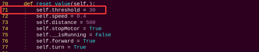
Note
After entering the line number in Vim, press Shift + G to jump directly to that line. The line number in the image is for reference only, please refer to the actual file.
(4) Press the i key to enter edit mode.
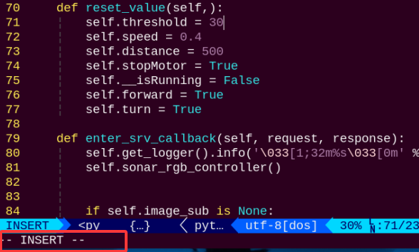
(5) Modify the line Threshold = 30.0, changing 30.0 to 20.0, as shown in the image below.
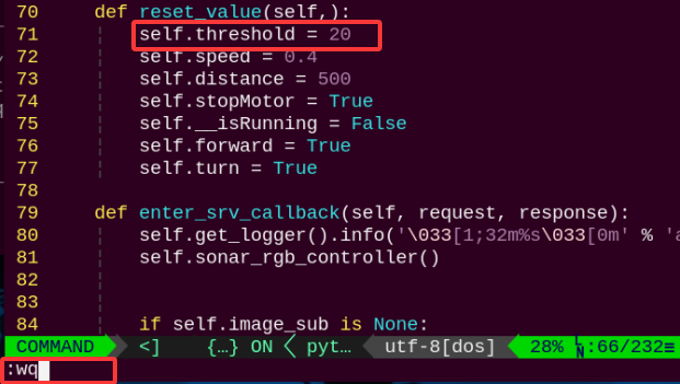
(6) After editing, press Esc, then type the command :wq and press Enter to save and exit
(7) Follow section 2 Enabling and Disabling the Feature in this guide to restart the feature. The robot will now turn left when the distance to an object is less than or equal to 20 cm.
Modify Speed
To change the robot’s movement speed, follow the steps below. In this example, we will change the speed value to make the robot moving at a speed of 20.
(1) Enter the following command and press Enter to navigate to the program’s source directory.
cd /home/ubuntu/ros2_ws/src/app/app
(2) Open the program file by entering the command.
vim avoidance_node.py
(3) In the opened file, locate the section as shown in the reference image.
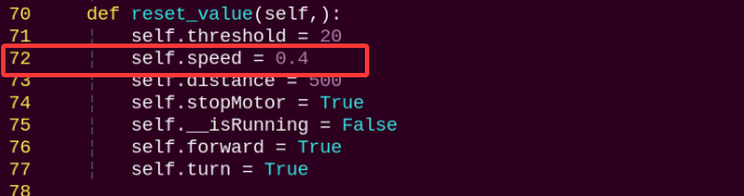
Note
After entering the line number in Vim, press Shift + G to jump directly to that line. The line number in the image is for reference only, please refer to the actual file.
(4) Press the i key to enter edit mode.
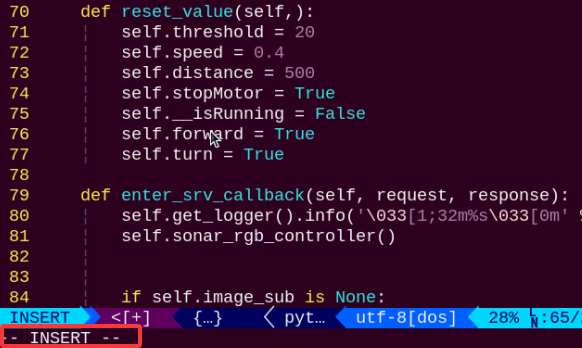
(5) Modify the line speed = 0.4, changing 0.4 to 0.2, as shown in the image below.
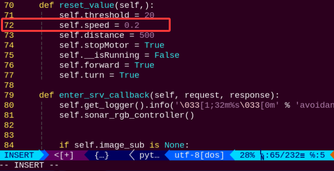
(6) After editing, press Esc, then type the command and press Enter to save and exit
:wq
(7) Follow 4.7.2 Enabling and Disabling the Feature in this guide to restart the feature. The robot will now move at a speed of 20.
4.8 Traffic Light Navigation
4.8.1 Brief Overview of Operation
In this lesson, the robot uses a camera to recognize traffic lights and a line follower sensor to follow a path. When a red light is detected, the robot stops and waits. When a green light is detected, the robot continues following the line. The traffic light navigation feature is composed of two parts: color recognition and line following. Let’s first take a look at the line-following part.
This part uses a 4-channel line-following sensor to enable the robot to stay on track by detecting the black line. The 4-channel line-following sensor consists of four probes, each with an infrared transmitter and infrared receiver.
Due to the fact that black surfaces absorb infrared light, when a probe is over a black background, the infrared receiver does not detect the infrared light emitted by the transmitter. After being processed by a Schmitt trigger, the sensor outputs a high-level signal (1). When the probe is over a white or light-colored background, the receiver does detect the infrared light, and the Schmitt trigger outputs a low-level signal (0). You can observe this by looking at the blue LED indicators on the back of the line sensor module: the LED turns on when the output is 1 and off when the output is 0. During movement, color recognition is used via the onboard camera. If the TurboPi detects a red traffic light, it will stop. If it detects a green traffic light, it will continue moving forward. For details on how color recognition works, refer to the documentation: 4.2 Color Recognition.
4.8.2 Enabling and Disabling the Feature
Note
When entering commands, be sure to use correct case and spacing. You can use the Tab key to auto-complete keywords.
(1) Power on the device and connect via VNC remote desktop tool.
(2) Click the terminal icon  in the upper-left corner of the system desktop to open a command-line window.

(3) Enter the following command to navigate to the directory where the feature’s program is located, then press Enter.
cd /home/ubuntu/ros2_ws/src/example/example
(4) Enter the following command to start the program and open the camera feed.
python3 line_follower.py
(5) Open a new red terminal window and enter the following command to launch the feature.
ros2 service call /start_game example_interfaces/srv/SetBool "{data: true}"
(6) To close this feature, first enter the command to stop the feature and press Enter in step 5). Then, in step 4), press Ctrl + C in the red terminal window to stop the program. If it doesn’t stop successfully the first time, you can press Ctrl + C multiple times.
ros2 service call /stop_game example_interfaces/srv/SetBool "{data: true}"
4.8.3 Project Outcome
Note
After placing the robot on the map, you need to adjust the camera angle to ensure that no part of the robot’s body is visible in the video feed. If the robot itself appears in the feed, it may interfere with the proper functioning of the feature.
Once the feature is activated, place the robot on the activity map with traffic lights and black tape lines. As the robot moves forward and reaches the traffic light, it will recognize the color of the light—stopping for red, and continuing for green.
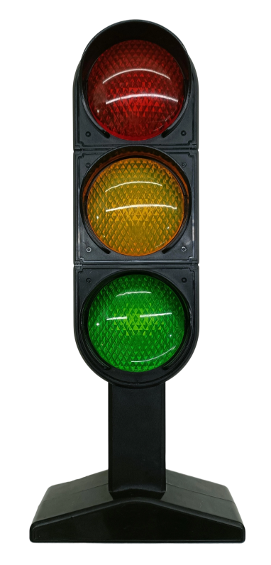
4.8.4 Program Brief Analysis
The source code for this demo is located at /home/ubuntu/ros2_ws/src/example/example/line_follower.py
Import the Necessary Libraries
(1) In Python, libraries are imported using the import statement. In this program, libraries such as cv2 for image processing, numpy for numerical computation, and rclpy for the ROS 2 framework are included to support image operations, mathematical calculations, and robot control.
1 2 3 4 5 6 7 8 9 10 11 12 13 14 15 16 17 | import sys import time import math import signal import threading import numpy as np import cv2 import yaml import rclpy from rclpy.node import Node from std_msgs.msg import String from geometry_msgs.msg import Twist from sensor_msgs.msg import Image from cv_bridge import CvBridge from rclpy.service import Service from example_interfaces.srv import SetBool import sdk.FourInfrared as infrared |
(2) Other commonly used libraries include those for OpenCV, time management, mathematics, and threading. To call a function from a library, use the format of library_name.function_name(parameter1, parameter2, …)
291 | cv2.imshow('Processed Frame', frame) |
Python also includes built-in libraries such as time, cv2, and math, which can be imported and used directly. Additionally, custom libraries can be created and used. For instance, the previously mentioned “CvBridge” file is a user-defined module for reading data.
(3) Aliasing Function Libraries
Some library names may be long or hard to remember. To simplify function calls, aliases are often used. For example:
297 298 299 | frame_resize = cv2.resize(img_copy, self.size, interpolation=cv2.INTER_NEAREST) frame_gb = cv2.GaussianBlur(frame_resize, (3, 3), 3) frame_lab = cv2.cvtColor(frame_gb, cv2.COLOR_BGR2LAB) |
After aliasing, functions from the cv2 library can be called in a format of cv2.function_name(parameter1, parameter2), which makes the code more convenient and easier to read.
Main Function Analysis
In Python, the main function of a program is defined as “__name__ == ‘__main__:’”. The program begins by calling the init() function to perform initialization. In this case, initialization includes resetting the servo to its initial position and reading the color threshold configuration file. Other typical initialization tasks may involve setting up ports, peripherals, and timers.
347 348 349 350 351 352 | def main(args=None): rclpy.init(args=args) robot_controller = RobotController() rclpy.spin(robot_controller) robot_controller.destroy_node() rclpy.shutdown() |
Node and Hardware Initialization
(1) Create the ROS2 node RobotController, and initialize topics, services, timers, and hardware interfaces.
21 22 23 24 25 26 27 28 29 | class RobotController(Node): def __init__(self): super().__init__('robot_controller') # Initialize publisher (发布者初始化) self.mecanum_pub = self.create_publisher(Twist, '/cmd_vel', 1) self.color_pub = self.create_publisher(String, '/detected_color', 10) self.rgb_pub = self.create_publisher(RGBStates, '/ros_robot_controller/set_rgb', 1) self.buzzer_pub = self.create_publisher(BuzzerState, '/ros_robot_controller/set_buzzer', 1) |
Parameter 1: "/cmd_vel"— publishes movement commands to control the robot, such as linear and angular velocity.
Parameter 2: "/detected_color" — publishes the detected color information.
Parameter 3: "/set_rgb" and "/set_buzzer" — used to control the RGB light and the buzzer.
(2) The node also provides services to start and stop the robot control feature.
49 50 51 | # Start and stop game services (启动和停止游戏服务) self.start_service = self.create_service(SetBool, 'start_game', self.start_game_callback) self.stop_service = self.create_service(SetBool, 'stop_game', self.stop_game_callback) |
(3) /image_raw is used to receive the raw camera feed.
54 | self.image_sub = self.create_subscription(Image, '/image_raw', self.image_callback, 10) |
(4) The infrared sensor reads data from the four-channel line-following sensor through the FourInfrared class.
56 57 | # Initialize infrared line-following sensors (初始化红外寻线传感器) self.line = infrared.FourInfrared() |
Image Processing
The input image is resized to a fixed resolution of 640×480 and then processed with Gaussian blur to reduce noise.
297 298 299 | frame_resize = cv2.resize(img_copy, self.size, interpolation=cv2.INTER_NEAREST) frame_gb = cv2.GaussianBlur(frame_resize, (3, 3), 3) frame_lab = cv2.cvtColor(frame_gb, cv2.COLOR_BGR2LAB) |
(1) Resizing helps standardize input for efficient processing.
297 | frame_resize = cv2.resize(img_copy, self.size, interpolation=cv2.INTER_NEAREST) |
The first parameter img_copy is the input image.
The second parameter self.size specifies the output image size.
The third parameter interpolation=cv2.INTER_NEAREST is the interpolation method.
INTER_NEAREST: Nearest neighbor interpolation.
INTER_LINEAR: Bilinear interpolation, default if unspecified.
INTER_CUBIC: Bicubic interpolation using a 4×4 pixel neighborhood.
INTER_LANCZOS4: Lanczos interpolation using an 8×8 neighborhood.
(2) Gaussian Blur
Images often contain noise, which can reduce clarity and make it harder to detect features. To reduce noise, different filtering methods can be applied depending on the type of noise. Common techniques include Gaussian blur, Median blur, and Mean blur.
Gaussian blur is a linear smoothing filter especially effective for reducing Gaussian noise. It’s widely used in image processing for denoising.
298 | frame_gb = cv2.GaussianBlur(frame_resize, (3, 3), 3) |
First parameter: frame_resize – the input image
Second parameter: (3, 3) – the size of the Gaussian kernel
Third parameter: 3 – the standard deviation in the X direction
(3) Convert the image to LAB color space, the function cv2.cvtColor() is used to convert the color space of an image.
299 | frame_lab = cv2.cvtColor(frame_gb, cv2.COLOR_BGR2LAB) |
First parameter: frame_gb – the input image
Second parameter: cv2.COLOR_BGR2LAB – conversion code that converts BGR format to LAB. If you want to convert from BGR to RGB instead, use cv2.COLOR_BGR2RGB.
(4) After the above processing, contour detection is used to identify the target object. The findContours() function from the cv2 library is used.
314 315 | contours = cv2.findContours(mask, cv2.RETR_EXTERNAL, cv2.CHAIN_APPROX_SIMPLE)[-2] contour, area = self.get_area_max_contour(contours) |
Parameter 1: closed — the input image
The second parameter cv2.RETR_EXTERNAL is the contour retrieval mode.
The third parameter cv2.CHAIN_APPROX_NONE)[-2] is the contour approximation method.
Among the detected contours, the one with the largest area is selected. To avoid interference, a minimum area threshold is set. Only contours with an area larger than this threshold are considered valid targets.
317 318 319 320 321 322 323 324 325 326 327 328 329 330 331 | if contour is not None and area > max_area: max_area = area color_area_max = color max_contour = contour if max_area > 2500 and max_contour is not None: rect = cv2.minAreaRect(max_contour) box = np.intp(cv2.boxPoints(rect)) cv2.drawContours(img, [box], -1, (0, 255, 0), 2) self.detect_color = color_area_max else: self.detect_color = "None" cv2.putText(img, "Color: " + self.detect_color, (10, img.shape[0] - 10), cv2.FONT_HERSHEY_SIMPLEX, 0.65, (255, 0, 0), 2) |
335 336 337 338 339 340 341 342 343 344 | def get_area_max_contour(self, contours): """Get largest contour and its area (获取面积最大的轮廓及其面积)""" area_max = 0 contour_max = None for c in contours: area = abs(cv2.contourArea(c)) if area > area_max and area > 300: # Area threshold to avoid noise (面积阈值避免噪声) area_max = area contour_max = c return contour_max, area_max |
(5) Displaying the Output
287 288 289 290 291 292 | def image_callback(self, img_msg): """Image callback: convert to OpenCV image and process for color detection (图像回调,转为OpenCV图像,处理颜色识别)""" img = self.bridge.imgmsg_to_cv2(img_msg, 'bgr8') frame = self.process_image(img) cv2.imshow('Processed Frame', frame) cv2.waitKey(1) |
The cv2.imshow() function displays the image in a window.
'frame' is the window name and frame_resize is the image to display. To ensure the window functions correctly, cv2.waitKey() must be included.
This function waits for a key input. The parameter 1 specifies the delay time.
Subthread Analysis
The robot’s movement function, line_following(), runs as a subthread. Once a color is detected, the line_following() function is triggered.
This mainly involves analyzing the image processing results and executing corresponding responses, including control of RGB lights, buzzer, 4-channel line follower, and other modules.
159 160 161 162 163 164 165 166 167 168 169 170 171 172 173 174 175 176 177 178 179 180 181 182 183 184 185 186 187 188 189 190 191 192 193 194 195 196 197 198 199 200 201 202 203 204 205 206 207 208 209 210 211 212 213 214 215 216 217 218 219 220 221 222 | def line_following(self): """ Line-following logic (sensor signal logic has been inverted): (巡线逻辑(已将传感器信号逻辑反转)) Now True means black line detected, False means no black line — as per your requirement (现在True表示检测到黑线,False表示未检测到黑线,符合您的需求。) """ raw_data = self.line.readData() # Invert sensor states to simplify later judgment, True means black line detected (反转传感器状态,方便后续判断,True表示检测到黑线) sensor_data = [not s for s in raw_data] self.get_logger().info(f"传感器状态(True检测到线): S0={sensor_data[0]}, S1={sensor_data[1]}, S2={sensor_data[2]}, S3={sensor_data[3]}") # Control movement based on inverted signal status (根据反转后的信号状态控制运动) if sensor_data[0] and not sensor_data[1] and sensor_data[2] and sensor_data[3]: self.get_logger().info("执行:右大转弯") self.sharp_right_turn() elif sensor_data[0] and sensor_data[1] and not sensor_data[2] and sensor_data[3]: self.get_logger().info("执行:左大转弯") self.sharp_left_turn() elif all(sensor_data): self.get_logger().info("所有传感器检测到黑线,停止机器人") self.stop_robot() elif sensor_data[0] and not sensor_data[1] and not sensor_data[2] and sensor_data[3]: self.get_logger().info("执行:直走") self.move_forward() elif not sensor_data[0] and not sensor_data[1] and sensor_data[2] and sensor_data[3]: self.get_logger().info("执行:左转") self.turn_left() elif sensor_data[0] and sensor_data[1] and not sensor_data[2] and not sensor_data[3]: self.get_logger().info("执行:右转") self.turn_right() elif sensor_data[0] and sensor_data[1] and not sensor_data[2] and sensor_data[3]: self.get_logger().info("执行:右转") self.turn_right() elif sensor_data[0] and not sensor_data[1] and sensor_data[2] and sensor_data[3]: self.get_logger().info("执行:左转") self.turn_left() elif sensor_data[0] and not sensor_data[1] and not sensor_data[2] and not sensor_data[3]: self.get_logger().info("执行:右大转弯") self.sharp_right_turn() elif not sensor_data[0] and not sensor_data[1] and not sensor_data[2] and sensor_data[3]: self.get_logger().info("执行:左大转弯") self.sharp_left_turn() elif sensor_data[0] and not sensor_data[1] and not sensor_data[2] and sensor_data[3]: self.get_logger().info("执行:直走") self.move_forward() elif sensor_data[0] and sensor_data[1] and sensor_data[2] and sensor_data[3]: self.get_logger().info("所有传感器都检测到线,继续前进") self.move_forward() else: self.get_logger().info("传感器状态异常,停止机器人") self.stop_robot() |
(1) Activating the RGB LED
The RGB LED color matches the detected color.
252 253 254 255 256 257 258 259 260 261 262 263 264 265 266 267 268 269 270 271 272 273 274 275 | def set_rgb(self, color): """Set RGB light color, mapping color name to RGB value (设置RGB灯颜色,根据色名字设定对应RGB值)""" rgb_msg = RGBStates() rgb_state1 = RGBState() rgb_state1.index = 1 rgb_state2 = RGBState() rgb_state2.index = 2 if color == "red": rgb_state1.red, rgb_state1.green, rgb_state1.blue = 255, 0, 0 rgb_state2.red, rgb_state2.green, rgb_state2.blue = 255, 0, 0 elif color == "green": rgb_state1.red, rgb_state1.green, rgb_state1.blue = 0, 255, 0 rgb_state2.red, rgb_state2.green, rgb_state2.blue = 0, 255, 0 elif color == "yellow": rgb_state1.red, rgb_state1.green, rgb_state1.blue = 255, 255, 0 rgb_state2.red, rgb_state2.green, rgb_state2.blue = 255, 255, 0 else: # Turn off light (关闭灯光) rgb_state1.red, rgb_state1.green, rgb_state1.blue = 0, 0, 0 rgb_state2.red, rgb_state2.green, rgb_state2.blue = 0, 0, 0 rgb_msg.states = [rgb_state1, rgb_state2] self.rgb_pub.publish(rgb_msg) self.get_logger().info(f"设置RGB灯为:{color}") |
(2) Triggering the Buzzer
277 278 279 280 281 282 283 284 285 | def play_buzzer(self): """Activate buzzer (激活蜂鸣器)""" buzzer_msg = BuzzerState() buzzer_msg.freq = 1000 # Frequency: 1000Hz (频率1000Hz) buzzer_msg.on_time = 0.1 # Buzz duration: 0.1 seconds (响铃时间0.1秒) buzzer_msg.off_time = 0.1 # Silence duration: 0.1 seconds (静音时间0.1秒) buzzer_msg.repeat = 1 # Repeat count (重复次数) self.buzzer_pub.publish(buzzer_msg) self.get_logger().info("蜂鸣器响起") |
The function setBuzzer() is used to activate the buzzer. Based on the code shown in the example image:
The first parameter 1000 is the frequency (Hz).
The second parameter 0.1 is the buzzer’s active time, in seconds.
The third parameter 0.1 is the buzzer’s off time, in seconds.
The fourth parameter 1 is the number of repetitions (default is 1).