5. MediaPipe Human-Robot Interaction
5.1 MediaPipe Introduction and Getting Started
5.1.1 Overview of MediaPipe
MediaPipe is an open-source framework designed for building multimedia machine learning pipelines. It supports cross-platform deployment on mobile devices, desktops, and servers, and can leverage mobile GPU acceleration. MediaPipe is compatible with inference engines such as TensorFlow and TensorFlow Lite, allowing seamless integration with models from both platforms. Additionally, it offers GPU acceleration on mobile and embedded platforms.

5.1.2 Advantages and Disadvantages of MediaPipe
5.1.2.1 Advantages of MediaPipe
MediaPipe supports various platforms and languages, including iOS, Android, C++, Python, JAVAScript, Coral, etc.
The performance is fast, and the model can generally run in real time.
Both the model and code allow for high reusability.
5.1.2.2 Disadvantages of MediaPipe
For mobile devices, MediaPipe will occupy 10 MB or more.
It heavily depends on TensorFlow, and switching to another machine learning framework would require significant code changes.
The framework uses static graphs, which improve efficiency but also make it more difficult to detect errors.
5.1.3 Workflow of Using MediaPipe
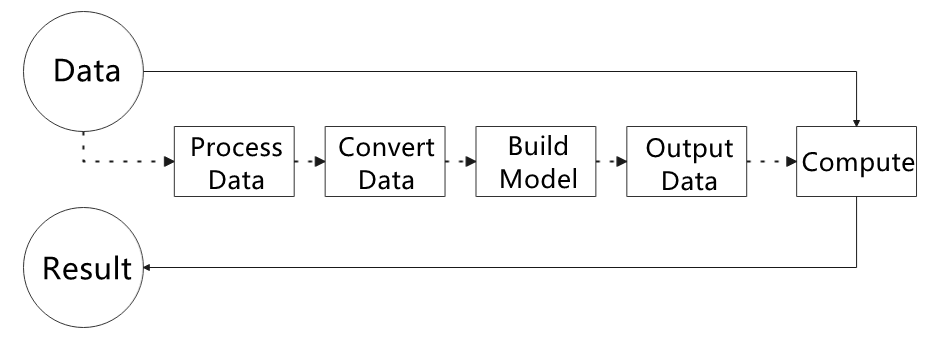
The figure below shows how to use MediaPipe. The solid line represents the part to be coded, and the dotted line indicates the part not to be coded. MediaPipe can offer the result and the function realization framework quickly.
5.1.3.1 Dependency
MediaPipe utilizes OpenCV to process video, and uses FFMPEG to process audio data. Furthermore, it incorporates other essential dependencies, including OpenGL/Metal, Tensorflow, and Eigen.
A basic understanding of OpenCV is recommended before working with MediaPipe. Refer to 9. OpenCV Computer Vision Course under the 1. Tutorials folder for an introduction to OpenCV.
5.1.3.2 MediaPipe Solutions
Solutions are based on the open-source pre-constructed sample of TensorFlow or TFLite. MediaPipe Solutions is built upon a framework that provides 16 Solutions, including face detection, Face Mesh, iris, hand, posture, human body, and so on.
5.1.4 Websites for MediaPipe Learning
MediaPipe Official Website: https://developers.google.com/mediapipe
MediaPipe Wiki: http://i.bnu.edu.cn/wiki/index.php?title=Mediapipe
MediaPipe github:https://github.com/google/mediapipe
dlib Official Website: http://dlib.net/
dlib github: https://github.com/davisking/dlib
5.2 Background Segmentation
In this lesson, MediaPipe’s Selfie Segmentation model is used to segment trained models from the background and then apply a virtual background, such as a face or a hand.
5.2.1 Program Introduction
First, the MediaPipe selfie segmentation model is imported, and real-time video is obtained by subscribing to the camera topic.
Next, the image is processed, and the segmentation mask is drawn onto the background image. Bilateral filtering is used to improve the segmentation around the edges.
Finally, the background is replaced with a virtual one.
5.2.2 Operation Steps
Power on the robot and connect it to a remote control tool like VNC.
Click the terminal icon
 in the system desktop to open a ROS2 command-line window.
Enter the following command in the terminal and press Enter to start the feature.
cd ~/ros2_ws/src/example/example/ && python3 self_segmentation.py

To exit this feature, press the Esc key in the image window to close the camera feed.
Alternatively, press Ctrl+C in the terminal. If the program does not close successfully, try pressing Ctrl+C again.
5.2.3 Project Outcome
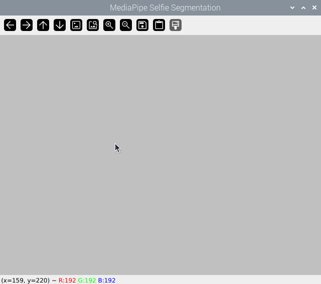
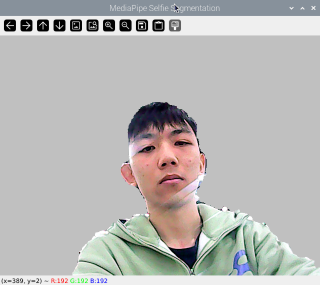
After the feature is started, the screen will show a completely gray virtual background. Once a person enters the frame, the person will be segmented from the background.
5.2.4 Program Analysis
The program file of the feature is located at: ~/ros2_ws/src/example/example/self_segmentation.py
5.2.4.1 Functions
main:
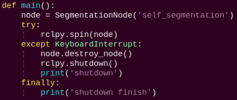
Starts the background segmentation node and executes the segmentation task.
5.2.4.2 Class
SegmentationNode:
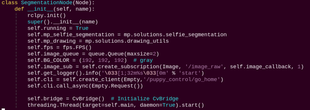
init: Initializes the parameters required for background segmentation, calls the image callback function, and starts the model inference function.
image_callback:

The image callback function is used to read data from the camera and enqueue it.
main:
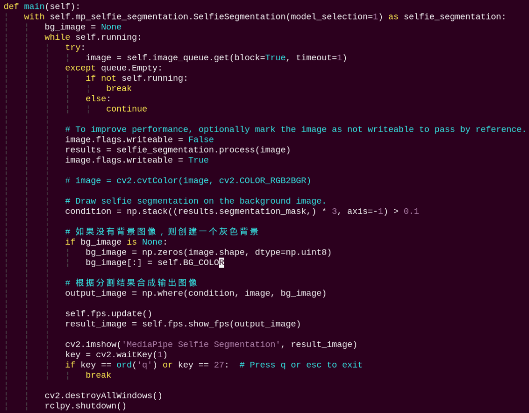
Reads the model from Mediapipe, inputs the image into the model, obtains the output image, and finally displays it using OpenCV.
5.3 3D Object Detection
5.3.1 Program Introduction
First, import MediaPipe’s 3D Objection and subscribe to the topic messages to obtain the real-time camera feed.
Next, apply preprocessing steps such as image flipping, and then perform 3D object detection on the images.
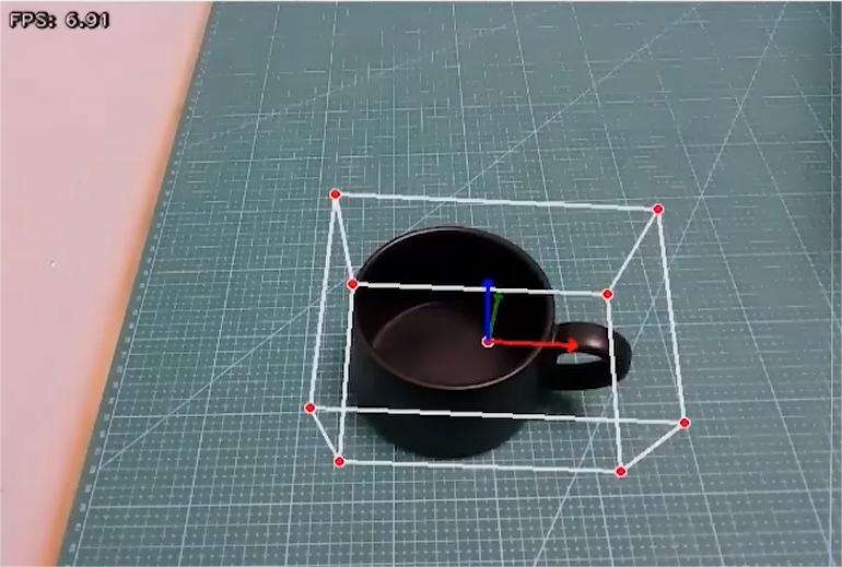
Finally, draw 3D bounding boxes on the detected objects in the image. In this section, a cup is used for demonstration.
5.3.2 Operation Steps
Power on the robot and connect it to a remote control tool like VNC.
Click the terminal icon
in the system desktop to open a ROS2 command-line window.Enter the following command in the terminal and press Enter to start the feature.
cd ~/ros2_ws/src/example/example/ && python3 objectron.py

To exit this feature, press the Esc key in the image window to close the camera feed.
Alternatively, press Ctrl+C in the terminal. If the program does not close successfully, try pressing Ctrl+C again.
5.3.3 Project Outcome
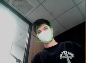
Once the program starts, a 3D bounding box will appear around the detected object in the camera view. Currently, four types of objects are supported: a cup with a handle, a shoe, a chair, and a camera. For example, when detecting a cup, the effect is shown as follows:
5.3.4 Program Analysis
The program file of the feature is located at:
~/ros2_ws/src/example/example/objectron.py
5.3.4.1 Functions
main:
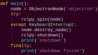
Used to start the 3D detection node.
5.3.4.2 Class
ObjectronNode:
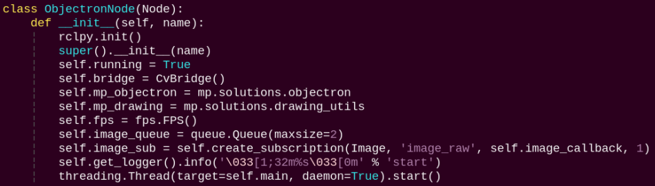
init: Initializes the parameters required for 3D recognition, calls the image callback function, and starts the model inference function.
image_callback:
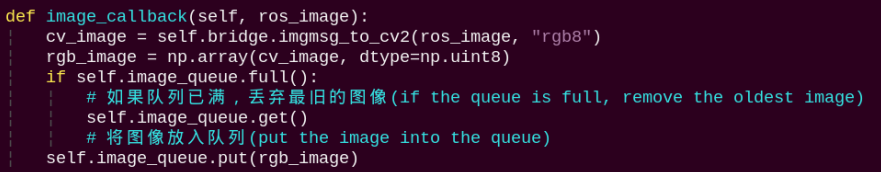
The image callback function is used to read data from the camera and enqueue it.
main:
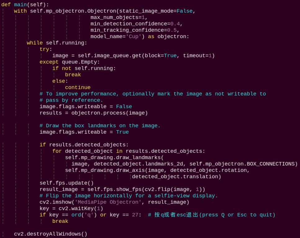
Loads the model from MediaPipe, feeds the image into the model, and then uses OpenCV to draw object edges and display the results.
5.4 Face Tracking
5.4.1 Program Introduction
In this session, the robot uses a camera to perform face detection, enabling both the car and the pan-tilt servos to follow the movement of a human face.
Among various applications of artificial intelligence, image recognition is one of the most widespread, with face recognition being one of the most prominent examples. It is commonly used in scenarios such as smart door locks and smartphone facial unlocking.
This face tracking feature consists of two main parts: face detection and tracking.
The process begins with face detection to locate faces in the image. A trained face model is then applied to detect faces on the scaled image. The detected face coordinates are converted back to the original image scale, allowing identification of the largest face, which is then highlighted with a bounding box.
Finally, based on the PID algorithm, the system compares the center of the image with the position of the detected face. It then adjusts the motors and servos accordingly to follow the face in real time.
The PID (Proportional–Integral–Derivative) algorithm is one of the most widely used automatic control methods. It operates by adjusting control inputs based on the proportional, integral, and derivative of the error. The PID controller is popular due to its simplicity, ease of implementation, broad applicability, and independently adjustable parameters.
5.4.2 Operation Steps
Power on the robot and connect it to a remote control tool like VNC.
Click the terminal icon
in the system desktop to open a ROS2 command-line window.Enter the following command and press Enter to navigate to the directory where the feature’s program is stored:
cd ~/ros2_ws/src/example/example

Enter the following command in the terminal and press Enter to start the feature. Two tracking modes are provided: tracking with the pan-tilt only and tracking with the chassis only. Pan-tilt-only tracking is the default mode.
For pan-tilt-only tracking, enter the following command:
python3 face_tracking.py

For chassis-only tracking, enter the following command:
python3 face_tracking.py --mode chassis

Open a new terminal window and enter the following command to launch the feature.
ros2 service call /face_landmarker/set_running std_srvs/srv/SetBool data:\\ true

To stop the feature, enter the following command in step 5’s terminal window.
ros2 service call /face_landmarker/set_running std_srvs/srv/SetBool data:\\ false

Finally, return to the terminal window opened in step 4 and press Ctrl+C to terminate the program. If it does not close immediately, press Ctrl+C multiple times.
5.4.3 Project Outcome
Note
For optimal performance, ensure that only one face is visible within the camera’s field of view. The presence of multiple faces may affect detection accuracy.
Once the feature is activated, the system searches for faces. When a face is detected, a bounding box is drawn around it, and the pan-tilt servos or the chassis will move to follow the face.
5.4.4 Program Analysis
The program file of the feature is located at:
~/ros2_ws/src/example/example/face_tracking.py
5.4.4.1 Functions
main:
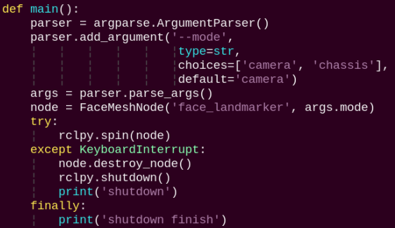
This function starts the face tracking node.
5.4.4.2 Class
FaceMeshNode:
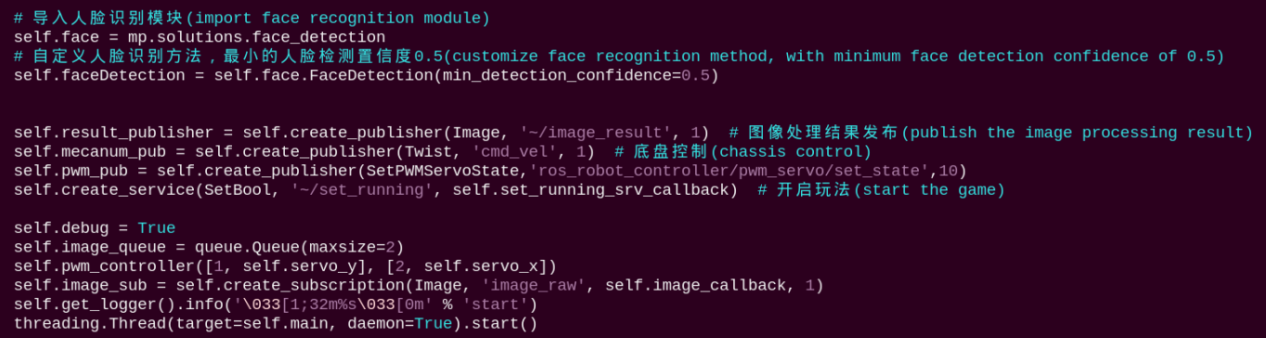
Initializes parameters and the face detection module, subscribes to the camera image topics, and publishes to the chassis and servo control topics.
image_callback:
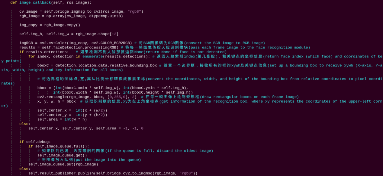
Subscribes to the image topic to perform face detection and calculate the face’s center coordinates and area.
main:
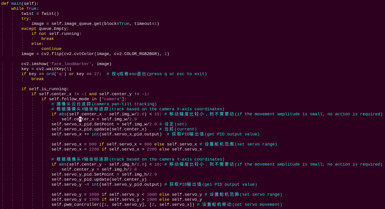
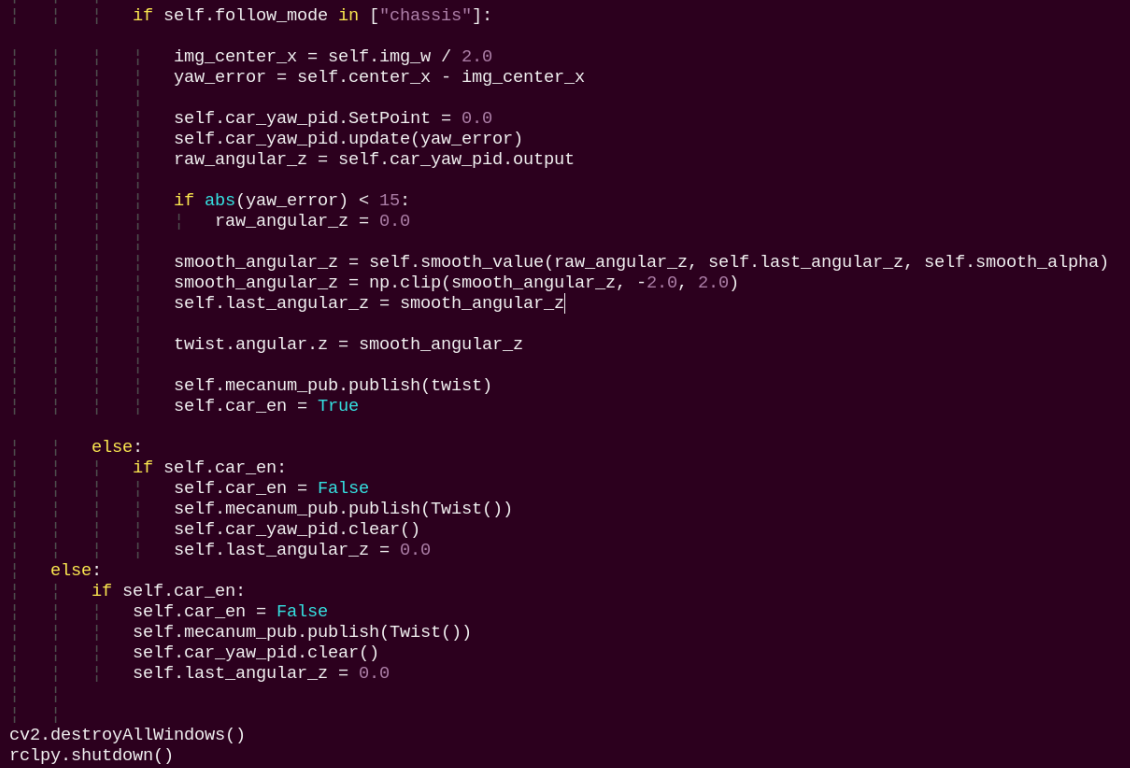
Reads the image queue, displays the images, and performs pan-tilt or chassis control for tracking based on the selected mode. In camera mode, the pwm_controller method is called to publish servo commands. In chassis mode, the X-axis error between the face center and the image center is calculated, and PID control outputs the chassis angular velocity.
5.5 3D Face Detection
In this program, MediaPipe Face Mesh is utilized to detect the human face within the camera image.
MediaPipe Face Mesh is a powerful model capable of estimating 468 3D facial features, even when deployed on a mobile device. It uses machine learning (ML) to infer 3D facial structure. This model leverages a lightweight architecture and GPU acceleration to deliver critical real-time performance.
Additionally, the solution is bundled with a face transformation module that bridges the gap between facial landmark estimation and practical real-time augmented reality (AR) applications. It establishes a metric 3D space and uses the screen positions of facial landmarks to estimate face transformations within that space. The face transformation data consists of common 3D primitives, including a facial pose transformation matrix and a triangulated face mesh.
5.5.1 Program Introduction
First, it’s important to understand that the machine learning pipeline used here, which can be thought of as a linear process, consists of two real-time deep neural network models working in tandem: One is a detector that processes the full image to locate faces. The other is a face landmark model that operates on those locations and uses regression to predict an approximate 3D surface.
For the 3D face landmarks, transfer learning was applied, and a multi-task network was trained. This network simultaneously predicts 3D landmark coordinates on synthetic rendered data and 2D semantic contours on annotated real-world data. As a result, the network is informed by both synthetic and real-world data, allowing for accurate 3D landmark prediction.
The 3D landmark model takes cropped video frames as input, without requiring additional depth input. It outputs the positions of 3D points along with a probability score indicating whether a face is present and properly aligned in the input.
After importing the face mesh model, subscribe to the topic messages to obtain the real-time camera feed.
The image is processed through operations such as flipping and color space conversion. Then, by comparing the face detection confidence to a predefined threshold, it determines whether a face has been successfully detected.
Finally, a 3D mesh is rendered over the detected face in the video feed.
5.5.2 Operation Steps
Power on the robot and connect it to a remote control tool like VNC.
Click the terminal icon
in the system desktop to open a ROS2 command-line window.Open a new command-line terminal, enter the command, and press Enter to run the program.
cd ~/ros2_ws/src/example/example/ && python3 face_mesh.py

To exit this feature, press the Esc key in the image window to close the camera feed.
Alternatively, press Ctrl+C in the terminal. If the program does not close successfully, try pressing Ctrl+C again.
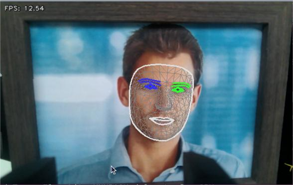
5.5.3 Project Outcome
Once the feature is started, the camera detects a face and highlights it with a bounding box in the returned video feed.
5.5.4 Program Analysis
The program file of the feature is located at:
~/ros2_ws/src/example/example/face_mesh.py
5.5.4.1 Functions
main:
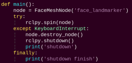
Used to launch the 3D face detection node.
5.5.4.2 Class
FaceMeshNode:
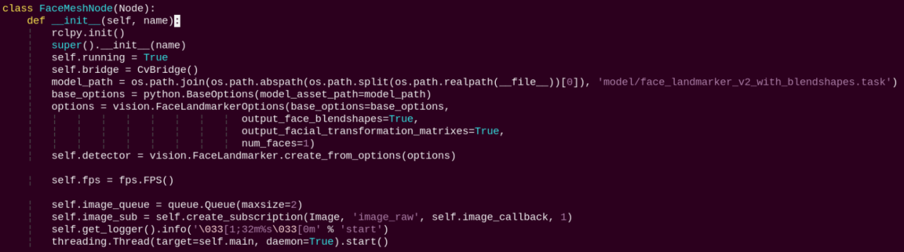
init: Initializes the parameters required for 3D face detection, calls the image callback function, and starts the model inference function.
image_callback:
The image callback function is used to read data from the camera and enqueue it.
main:
Loads the model from MediaPipe, feeds the image into it, and uses OpenCV to draw facial keypoints and display the returned video feed.
5.6 Hand Keypoint Detection
In this lesson, MediaPipe’s hand detection model is used to display hand keypoints and the connecting lines between them on the returned image.
MediaPipe Hands is a high-fidelity hand and finger tracking model. It uses machine learning (ML) to infer 21 3D landmarks of a hand from a single frame.
5.6.1 Program Introduction
First, it’s important to understand that MediaPipe’s palm detection model utilizes a machine learning pipeline composed of multiple models, which is a linear model, similar to an assembly line. The model processes the entire image and returns an oriented hand bounding box. The hand landmark model then operates on the cropped image region defined by the palm detector and returns high-fidelity 3D hand keypoints.
After importing the hand detection model, the system subscribes to topic messages to acquire real-time camera images.
The images are then processed with flipping and color space conversion, which greatly reduces the need for data augmentation for the hand landmark model.
In addition, the pipeline can generate crops based on the hand landmarks recognized in the previous frame. The palm detection model is only invoked to re-locate the hand when the landmark model can no longer detect its presence.
Next, the system compares the detection confidence against the model’s minimum threshold to determine if hand detection is successful.
Finally, it detects and draws the hand keypoints on the output image.
5.6.2 Operation Steps
Power on the robot and connect it to a remote control tool like VNC.
Click the terminal icon
in the system desktop to open a ROS2 command-line window.Open a new command-line terminal, enter the command, and press Enter to run the program.
cd ~/ros2_ws/src/example/example/ && python3 hand.py

To exit the feature, press Ctrl+C in the terminal. If the program does not close successfully, try pressing Ctrl+C again.
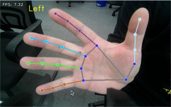
5.6.3 Project Outcome
After starting the feature, once the camera detects a hand, the returned image will display the hand landmarks along with the connections between them.
5.6.4 Program Analysis
The program file of the feature is located at:
~/ros2_ws/src/example/example/hand.py
5.6.4.1 Functions
main:
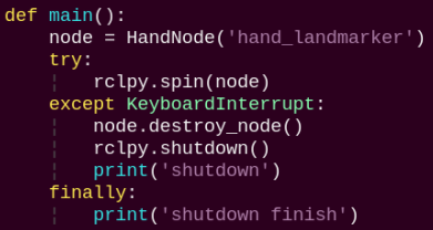
Used to start the hand keypoint detection node.
5.6.4.2 Class
HandNode:
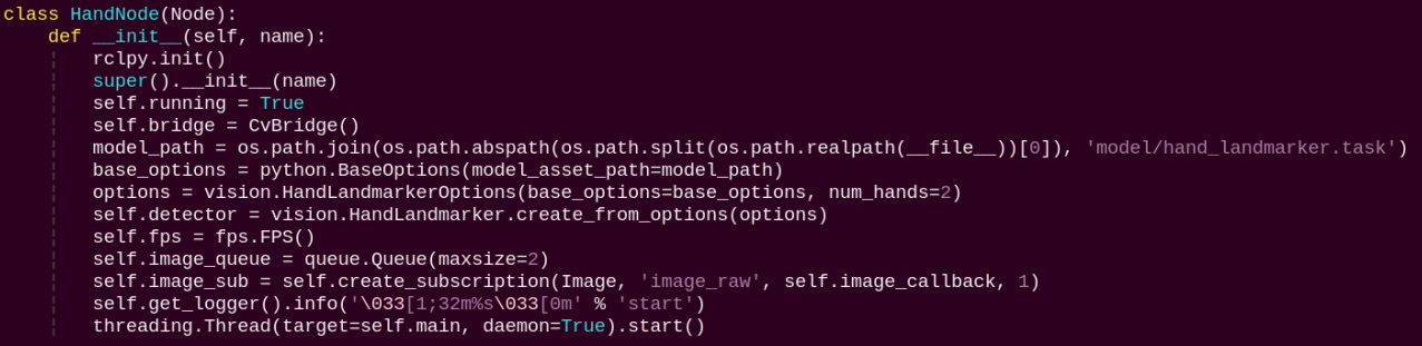
init: Initializes the parameters required for hand keypoints detection, calls the image callback function, and starts the model inference function.
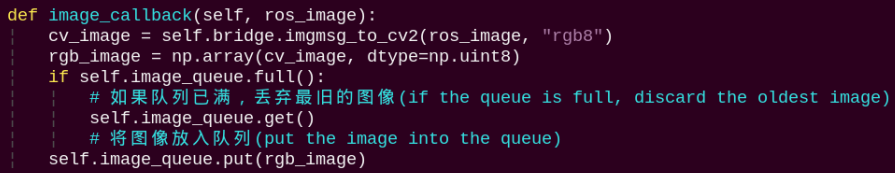
image_callback:
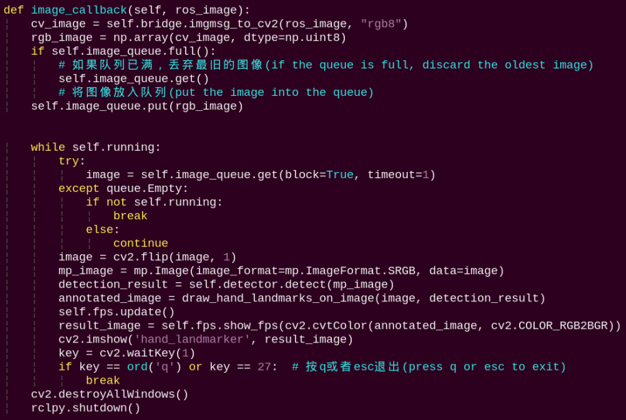
The image callback function is used to read data from the camera and enqueue it.
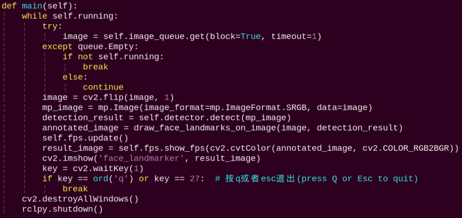
Loads the model from MediaPipe, feeds the image into it, and uses OpenCV to draw the hand’s keypoints and display the returned video feed.
5.7 Body Keypoint Detection
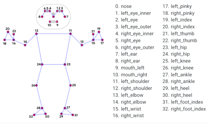
In this lesson, MediaPipe’s pose detection model is used to detect body landmarks and display them on the video feed.
MediaPipe Pose is a high-fidelity body pose tracking model. Powered by BlazePose, it infers 33 3D landmarks across the full body from RGB input. This research also supports the ML Kit Pose Detection API.
5.7.1 Program Introduction
First, import the pose detection model. Then, the program applies image preprocessing such as flipping and converting the color space. By comparing against a minimum detection confidence threshold, it determines whether the human body is successfully detected.
Next, it uses a minimum tracking confidence threshold to decide whether the detected pose can be reliably tracked. If not, the model will automatically re-invoke detection on the next input image.
The pipeline first identifies the region of interest (ROI) containing the person’s pose in the frame using a detector. The tracker then uses the cropped ROI image as input to predict pose landmarks and segmentation masks within that area. For video applications, the detector is only invoked when necessary—such as for the first frame or when the tracker fails to identify a pose from the previous frame. For all other frames, the ROI is derived from the previously tracked landmarks.
After importing the MediaPipe pose detection model, subscribe to the topic messages to obtain the real-time video stream from the camera.
Finally, it identifies and draws the body landmarks on the image.
5.7.2 Operation Steps
Power on the robot and connect it to a remote control tool like VNC.
Click the terminal icon
in the system desktop to open a ROS2 command-line window.Open a new command-line terminal, enter the command, and press Enter to run the program.
cd ~/ros2_ws/src/example/example/ && python3 pose.py

To exit the feature, press Ctrl+C in the terminal. If the program does not close successfully, try pressing Ctrl+C again.
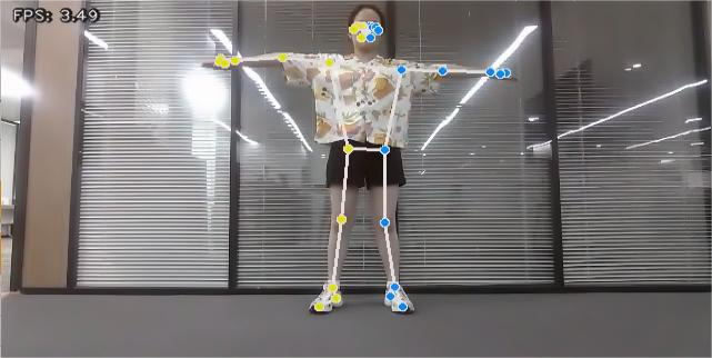
5.7.3 Project Outcome
After the program is launched, the camera performs human pose estimation and displays the detected keypoints and their connections on the video feed.
5.7.4 Program Analysis
The program file of the feature is located at:
~/ros2_ws/src/example/example/pose.py
5.7.4.1 Functions
main:
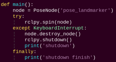
Used to start the body detection node.
5.7.4.2 Class
PoseNode:
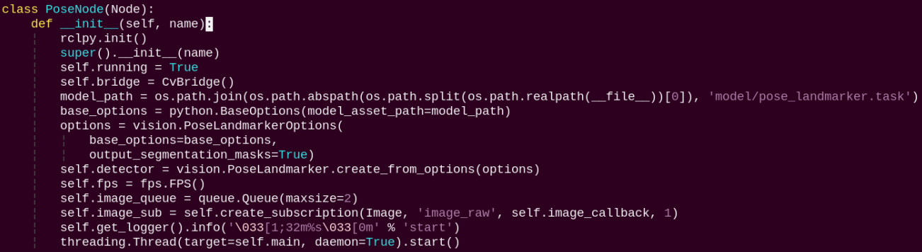
init: Initializes the parameters required for body keypoints detection, calls the image callback function, and starts the model inference function.
image_callback:
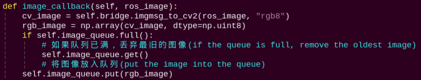
The image callback function is used to read data from the camera and enqueue it.
main:
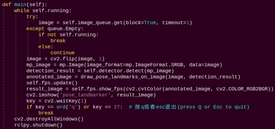
Loads the MediaPipe model, feeds the image into the model, and then uses OpenCV to draw body keypoints on the output image and display the processed view.
5.8 Fingertip Distance Recognition
The robot uses MediaPipe’s hand detection model to recognize palm joints. Once a hand is detected, the robot identifies the fingertips in the image and draws lines connecting them.
5.8.1 Program Introduction
First, the MediaPipe hand detection model is called to process the camera feed. Next, the image is flipped and processed to detect hand information within the frame. Finally, the robot detects the fingertips in the image and draws a line between the two fingertips.
5.8.2 Operation Steps
Note
When entering commands, be sure to use correct case and spacing. You can use the Tab key to auto-complete keywords.
Power on the robot and connect it to a remote control tool like VNC.
Click the terminal icon
in the system desktop to open a ROS2 command-line window.Open a new command-line terminal, enter the command, and press Enter to run the program.
cd ~/ros2_ws/src/example/example/ && python3 hand_gesture.py

To exit the feature, press Ctrl+C in the terminal. If the program does not close successfully, try pressing Ctrl+C again.
5.8.3 Project Outcome
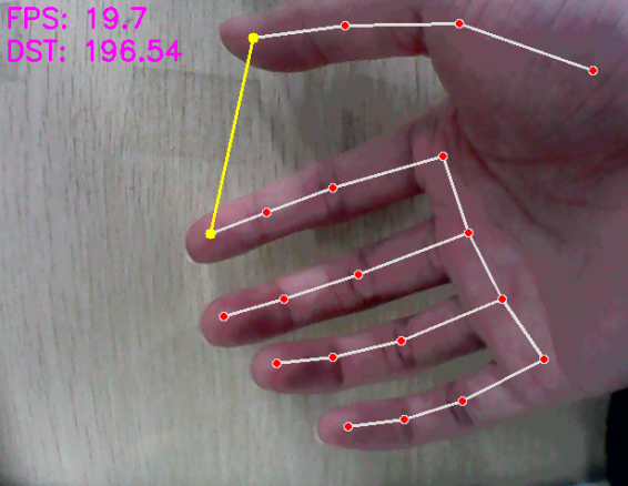
After starting the feature, place your hand within the camera’s field of view. When a hand is detected, the returned image highlights the hand keypoints and draws a line connecting the two fingertips.
5.8.4 Program Analysis
The program file of the feature is located at:
~/ros2_ws/src/example/example/hand_gesture.py
Note
Before modifying the program, be sure to back up the original factory program. Do not modify the source code files directly. Incorrect parameter changes may cause the robot to behave abnormally and become irreparable!
5.8.4.1 Functions
main:
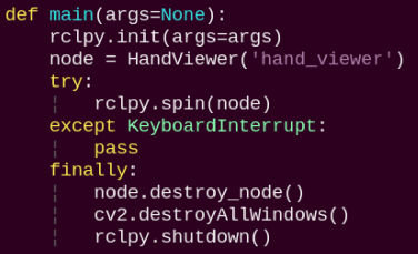
Used to start the fingertip distance recognition node.
5.8.4.2 Class
HandViewer:
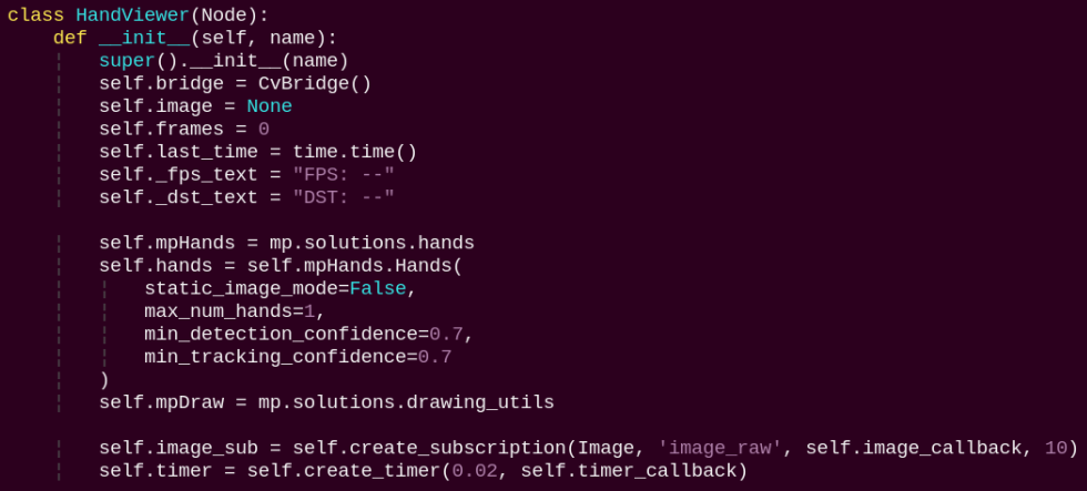
The init function initializes the module and subscribes to the camera image topic.
image_callback:
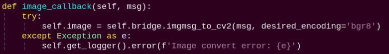
Image callback function converts camera images to OpenCV format for processing.
timer_callback:
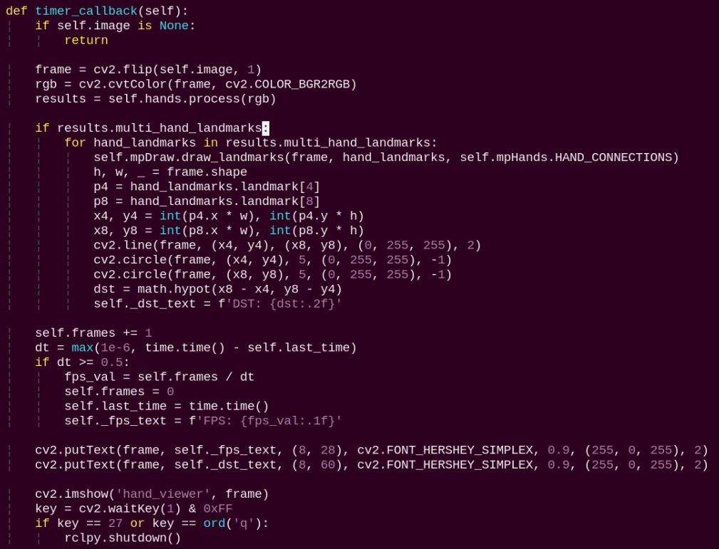
Preprocesses the image with a mirror flip, detects hand keypoints, draws the keypoints and connecting lines, obtains the coordinates of the thumb and index fingertips and draws a line between them, and calculates the Euclidean distance between the two fingertips.
5.9 Body Gesture Control
Using the human pose estimation model trained with the MediaPipe machine learning framework, the system detects the human pose in the camera feed and marks the relevant joint positions. Based on this, multiple actions can be recognized in sequence, allowing direct control of the robot through body gestures.
From the robot’s first-person perspective:
Raising the left arm causes the robot to move a certain distance to the right. Raising the right arm causes the robot to move a certain distance to the left. Raising the left leg causes the robot to move forward a certain distance. Raising the right leg causes the robot to move backward a certain distance.
5.9.1 Program Introduction
First, the MediaPipe human pose estimation model is imported, and the camera feed is accessed by subscribing to the relevant topic messages.
MediaPipe is an open-source framework designed for building multimedia machine learning pipelines. It supports cross-platform deployment on mobile devices, desktops, and servers, and can leverage mobile GPU acceleration. It also supports inference engines for TensorFlow and TensorFlow Lite.
Next, using the constructed model, key points of the human torso are detected in the camera feed. These key points are connected to visualize the torso, allowing the system to determine the body posture.
Finally, if the user performs a specific action, the robot responds accordingly.
5.9.2 Operation Steps
Note
When entering commands, be sure to use correct case and spacing. You can use the Tab key to auto-complete keywords.
Power on the robot and connect it to a remote control tool like VNC.
Click the terminal icon
in the system desktop to open a ROS2 command-line window.Enter the following command and press Enter to start the feature.
cd ~/ros2_ws/src/example/example/ && python3 body_control.py

To exit this feature, press the Esc key in the image window to close the camera feed.
Alternatively, press Ctrl+C in the terminal. If the program does not close successfully, try pressing Ctrl+C again.
5.9.3 Project Outcome
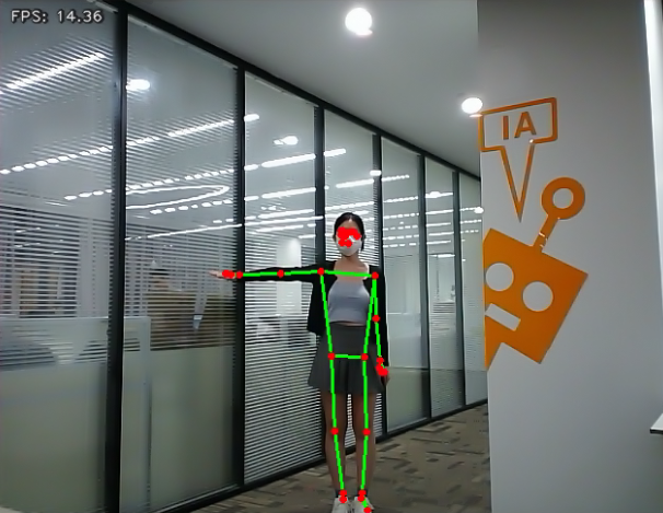
After starting the feature, stand within the camera’s field of view. When a human body is detected, the returned video feed will display the key points of the torso along with lines connecting them.
From the robot’s first-person perspective:
Raising the left arm causes the robot to move a short distance to the right. Raising the right arm causes the robot to move a short distance to the left. Raising the left leg causes the robot to move forward a short distance. Raising the right leg causes the robot to move backward a short distance.
5.9.4 Program Analysis
The program file of the feature is located at:
~/ros2_ws/src/example/example/body_control.py
Note
Before modifying the program, be sure to back up the original factory program. Do not modify the source code files directly. Incorrect parameter changes may cause the robot to behave abnormally and become irreparable!
5.9.4.1 Functions
main:
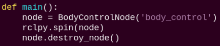
Starts the body motion control node.
get_joint_landmarks:
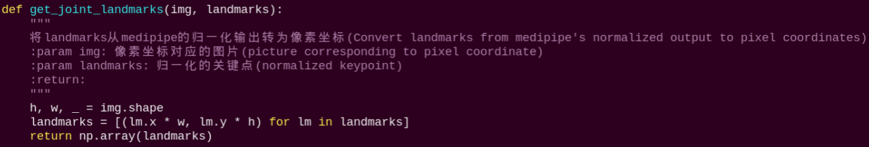
Converts the detected information into pixel coordinates.
joint_distance:
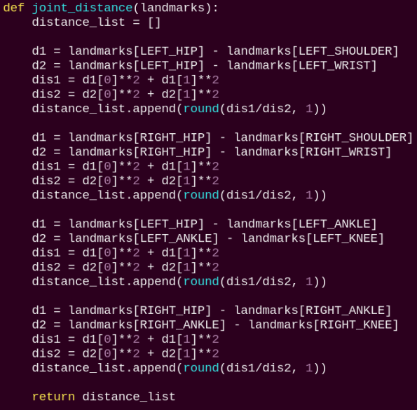
Calculates the distances between joints based on pixel coordinates.
5.9.4.2 Class
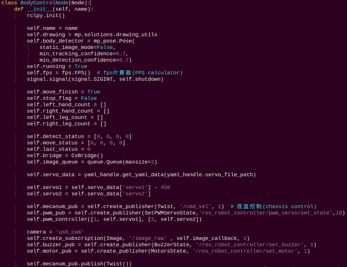
Initializes parameters, subscribes to image topics, and publishes topics for controlling servos, the chassis, and the buzzer.
get_node_state:
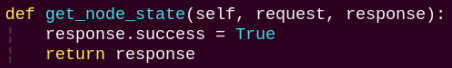
Sets the current initialization state of the node.
shutdown:
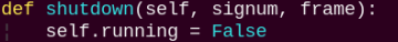
A callback function to terminate the recognition process upon program exit.
image_callback:

The image callback function processes incoming images and places them into a queue.
move:
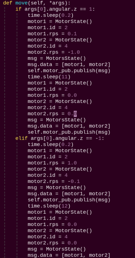
Motion strategy function controls the robot’s movement according to the detected body actions.
buzzer_warn:
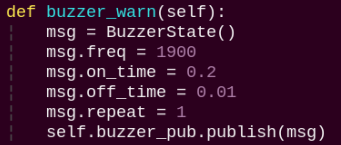
Buzzer control function triggers buzzer alerts.
image_proc:
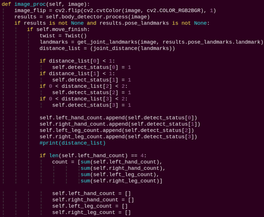
The image processing routine applies the model to draw body keypoints based on the detected results and drives motion according to the recognized pose.
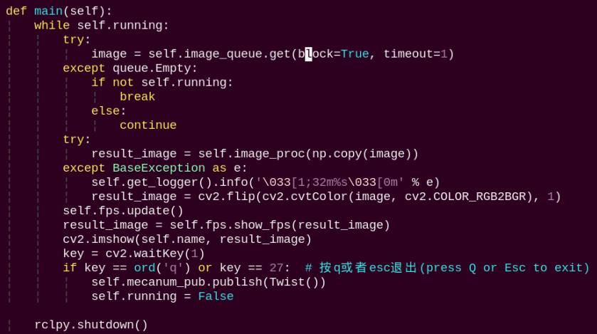
main:
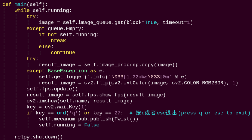
The main function feeds image data into the recognition routine and displays the returned video stream.
5.10 Human Pose Detection
In this program, a human pose estimation model from the MediaPipe machine learning framework is used to detect human poses. Upon detecting a fall, the robot issues an alert and moves back and forth.
5.10.1 Program Introduction
First, the MediaPipe human pose estimation model is imported, and the camera feed is accessed by subscribing to the relevant topic messages.
Next, the image is flipped and processed to detect human body information within the frame. Based on the connections between human keypoints, the system calculates the body height to determine body movements.
Finally, if a fall is detected, the robot will trigger an alert and move forward and backward.
5.10.2 Operation Steps
Note
When entering commands, be sure to use correct case and spacing. You can use the Tab key to auto-complete keywords.
Power on the robot and connect it to a remote control tool like VNC.
Click the terminal icon
in the system desktop to open a ROS2 command-line window.Enter the following command and press Enter to start the feature.
cd ~/ros2_ws/src/example/example/ && python3 fall_down_detect.py

To exit this feature, press the Esc key in the image window to close the camera feed.
Alternatively, press Ctrl+C in the terminal. If the program does not close successfully, try pressing Ctrl+C again.
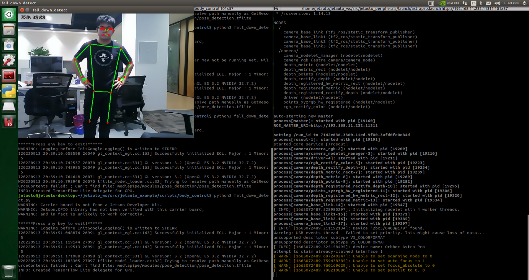
5.10.3 Project Outcome
After starting the feature, make sure the person is fully within the camera’s field of view. When a person is detected, the keypoints of the body will be marked on the live feed.
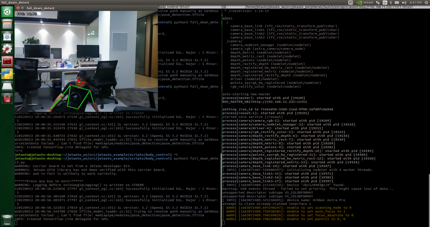
If the person slightly sits down and the robot recognizes a fall posture, it will continuously sound an alert and repeatedly move forward and backward as a warning.
5.10.4 Program Analysis
The program file of the feature is located at:
~/ros2_ws/src/example/example/fall_down_detect.py
Note
Before modifying the program, be sure to back up the original factory program. Do not modify the source code files directly. Incorrect parameter changes may cause the robot to behave abnormally and become irreparable!
5.10.4.1 Functions
main:
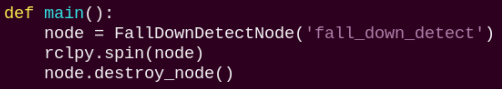
The main function is used to start the human pose detection node.
get_joint_landmarks:
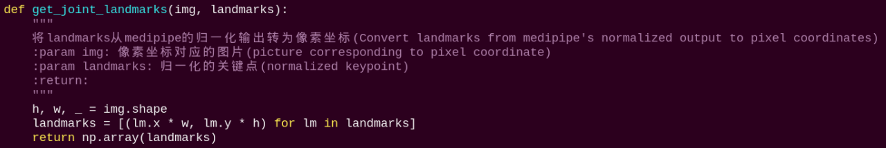
Converts the detected information into pixel coordinates.
height_cal:
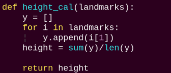
Calculates the body height based on the detected information.
5.10.4.2 Class
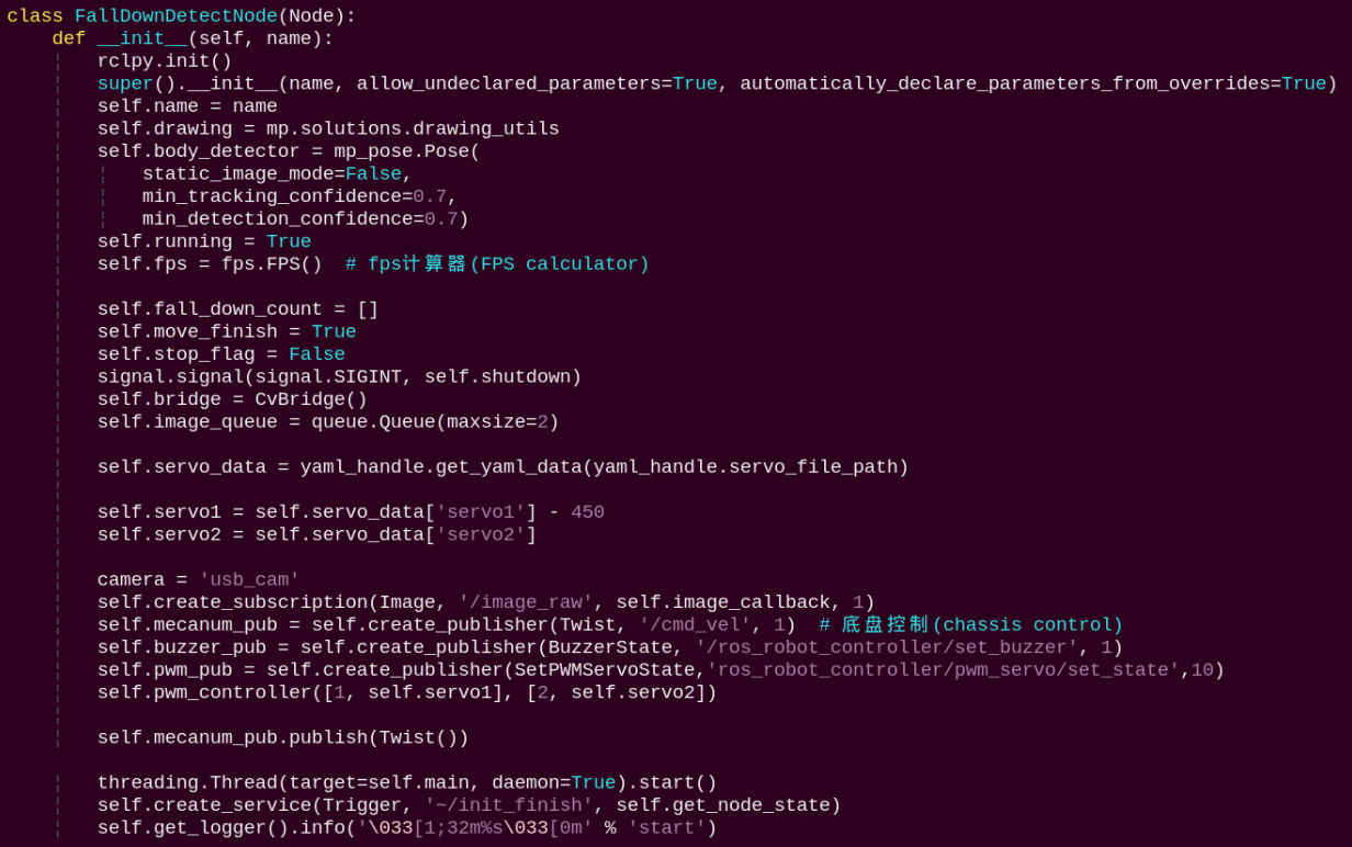
Initializes parameters, subscribes to camera image topics, and publishes topics for controlling the chassis and the buzzer.
get_node_state:
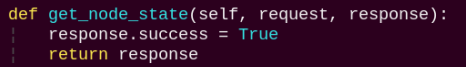
Sets the current initialization state of the node.
shutdown:
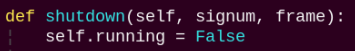
A callback function to terminate the recognition process upon program exit.
image_callback:
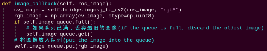
The image callback function processes incoming images and places them into a queue.
move:
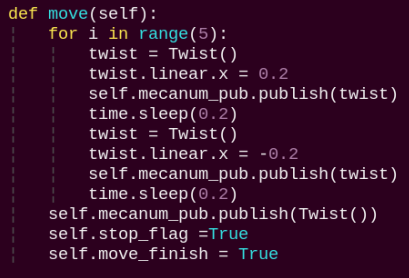
Motion strategy function controls the robot’s movement according to the detected body height.
buzzer_warn:
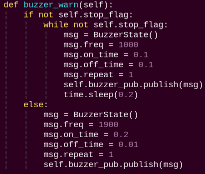
Buzzer control function triggers buzzer alerts.
image_proc:
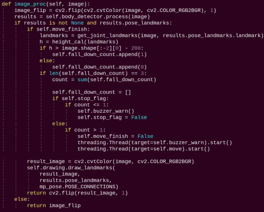
The image processing routine applies the model to draw human keypoints based on the detected results and drives motion according to the estimated height.
main:
The main function feeds image data into the recognition routine and displays the returned video stream.