1. Getting Started
1.1 NexArm Overview
NexArm is a high-performance open-source robotic arm developed by Hiwonder for AI education. Built on an ESP32 controller, it combines deeply optimized control algorithms with a modern open-source ecosystem, delivering a full-stack solution from low-level hardware control to end-to-end large AI model validation.
With an industrial-grade all-metal body, high-precision magnetic encoder servos in the core joints, a rotating pan-tilt unit, and a precision rail gripper, NexArm provides an effective working radius of up to 500 mm. The built-in advanced inverse kinematics algorithm supports Cartesian coordinate control and complex motion planning, enabling accurate and reliable grasping and trajectory execution.
Designed for imitation learning, NexArm supports a Leader-Follower teleoperation system consisting of a leader arm and a follower arm. Its low-level architecture is deeply compatible with the latest Hugging Face LeRobot framework. Low-latency teleoperation enables millisecond-level motion mapping, making NexArm an excellent entry-level validation platform for end-to-end Vision-Language-Action model research.
NexArm provides rich hardware interfaces and expansion options. It supports the K230 vision module for visual tracking and grasping with high-precision hand-eye coordination, and can also connect seamlessly to mobile chassis, linear slide rails, conveyor belts, and other peripherals. Combined with the multimodal large AI models built into the vision module, NexArm supports in-depth development for large AI model interaction and multimodal embodied intelligence applications.
NexArm is deeply adapted to the LeRobot open-source project, with full compatibility across low-level drivers and inverse kinematics parameters. Core resources from the Hugging Face community, including pretrained models, real-robot demonstration datasets, and simulation environments, can be reused directly without tedious low-level configuration. With a Raspberry Pi, an NVIDIA platform, or a PC with a dedicated graphics card, end-to-end algorithms such as ACT can run smoothly. From simulation training to real-robot deployment, NexArm helps complete the full development loop for imitation learning and reinforcement learning, keeping the focus on core algorithm validation.
1.2 App Control
1.2.1 App Download
For iOS devices, search for Wonderbot in the App Store and download the app.
For Android devices, install the Wonderbot-V2.3.4.apk from 5. NexArm App Installation Package in folder 2. Softwares.
Note
iOS and Android devices can scan the QR code below to download and install the app. iOS 12.0 or later is required, and Android 5.0 or later is required.
Android devices must grant all app permissions in the phone settings. Otherwise, some functions may not work properly.
1.2.2 App Connection
Note
NexArm is shipped with Bluetooth connection enabled by default. After the robotic arm is powered on, the corresponding Bluetooth device can be found in the app. Press the button key2 to switch between PS3 controller mode and app control mode.
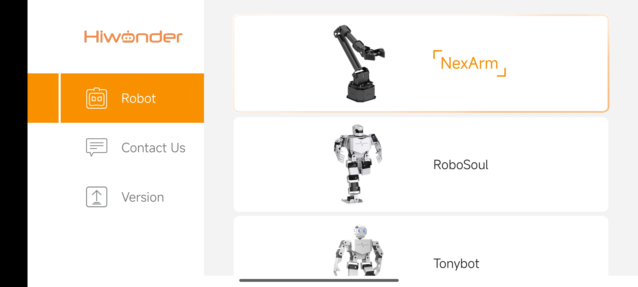
Open the app, tap Robot on the left side, find NexArm in the pop-up options, and tap it to enter the control interface.
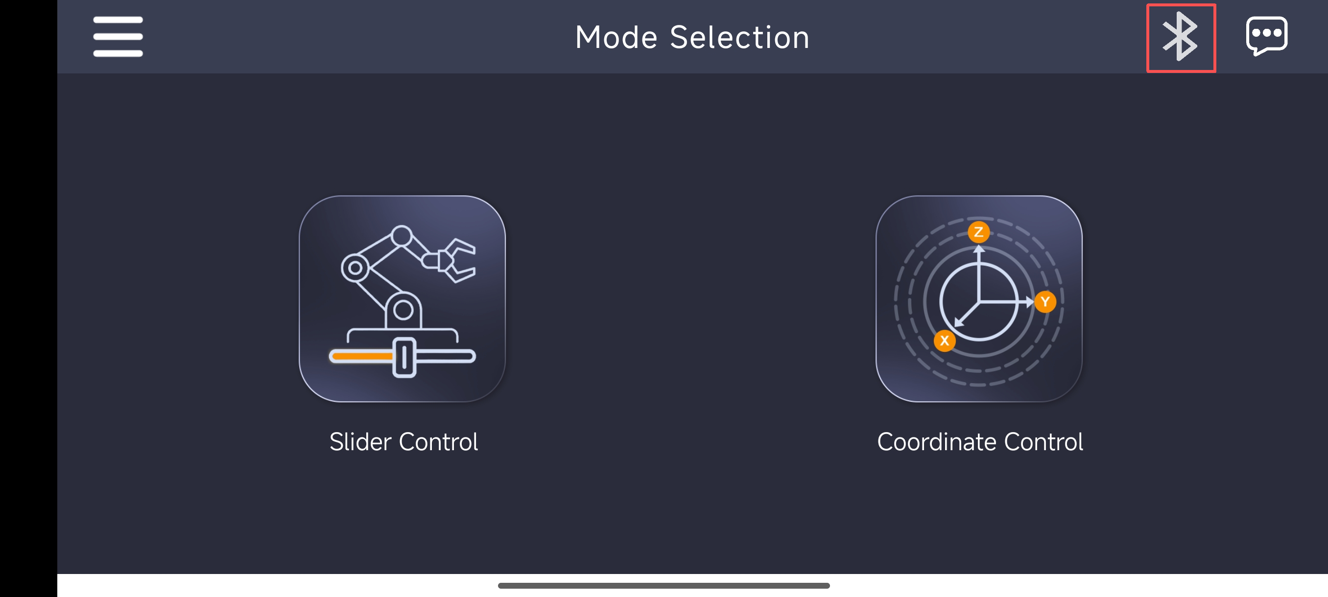
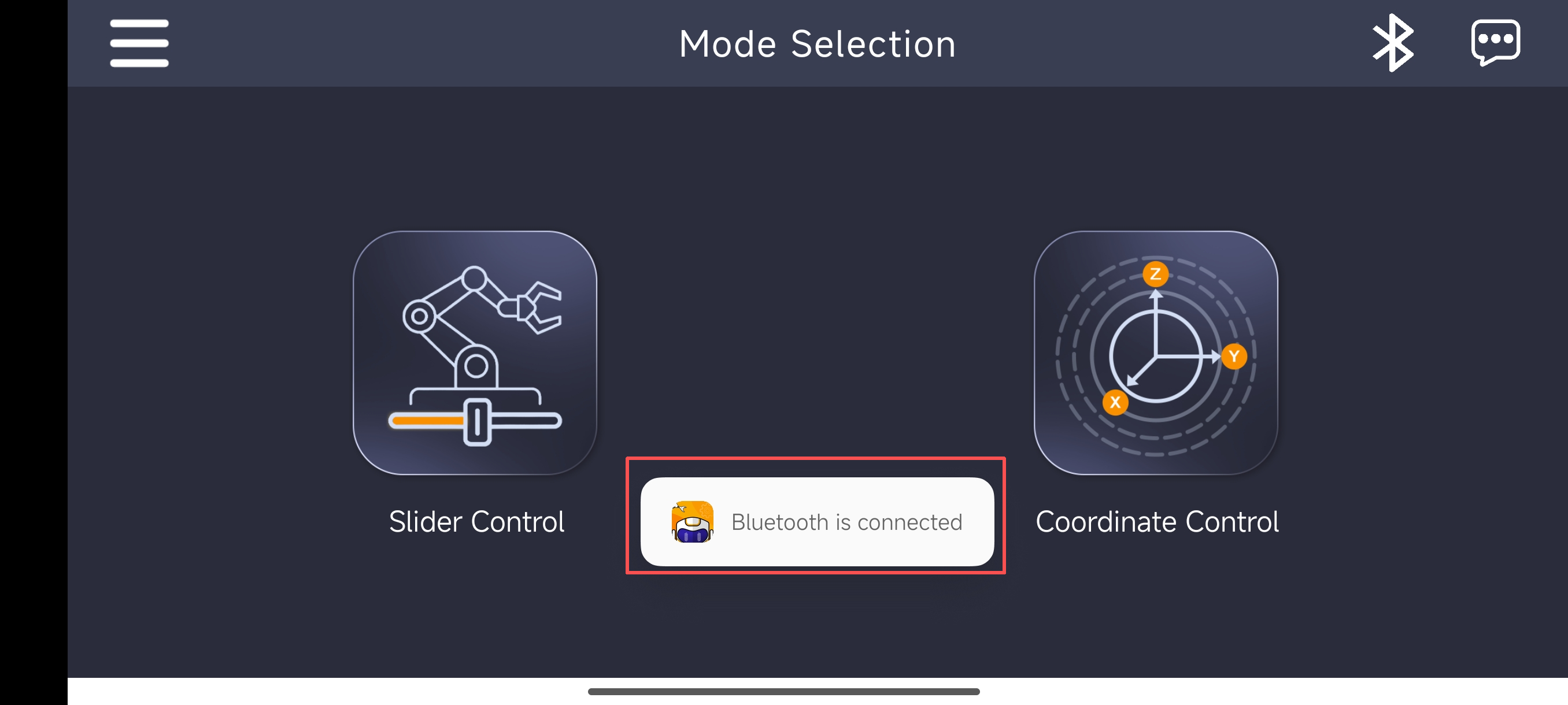
After entering the control interface, the Mode Selection screen will appear. Tap the Bluetooth icon in the upper-right corner to connect Bluetooth first.
Connect NexArm to the original power adapter, turn on the power switch, and wait a few seconds. Tap the Bluetooth connection icon in the app. When the Bluetooth list appears, find Nex_Arm and tap it to connect.
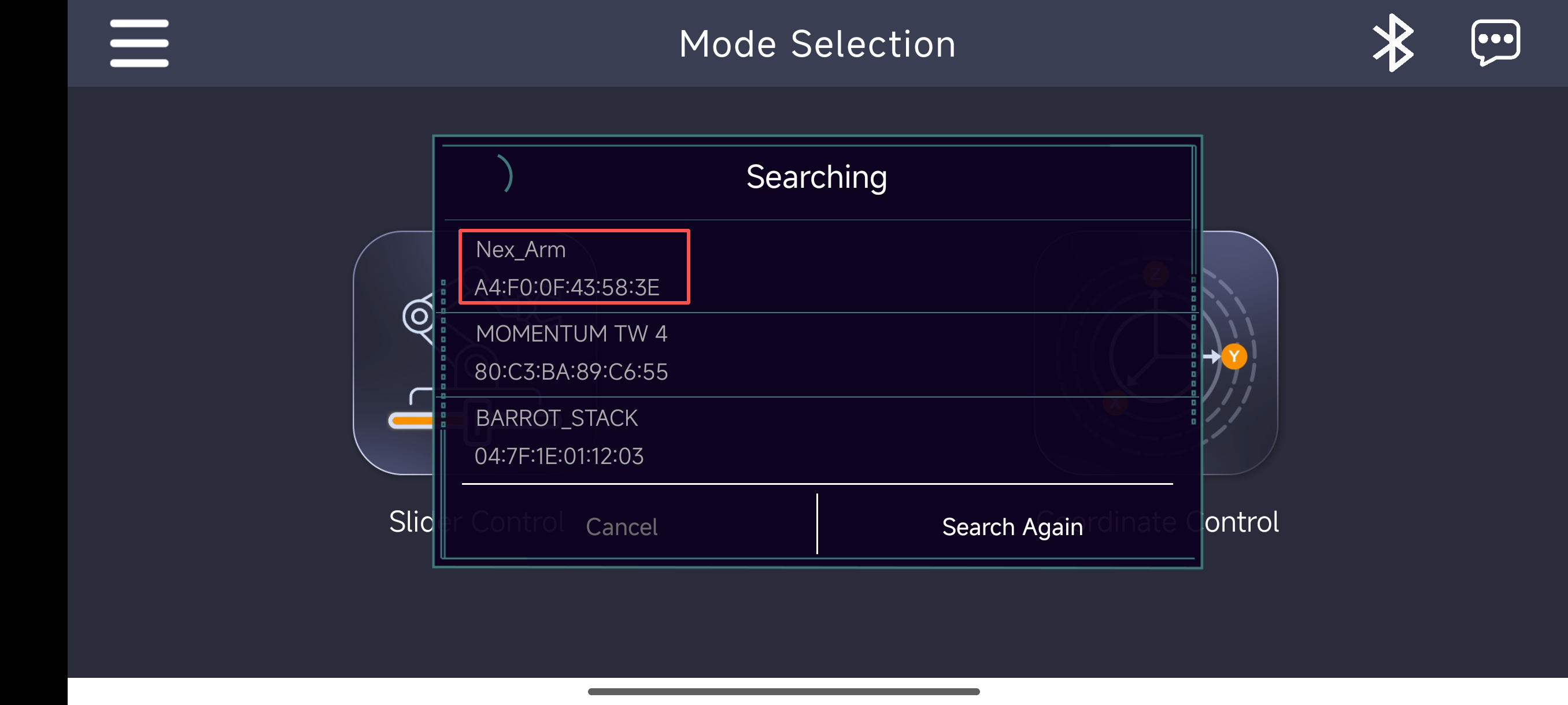
After a successful connection, the Bluetooth list closes automatically, and the notification Bluetooth is connected is displayed.
1.2.3 Function Overview
Slider Control Mode
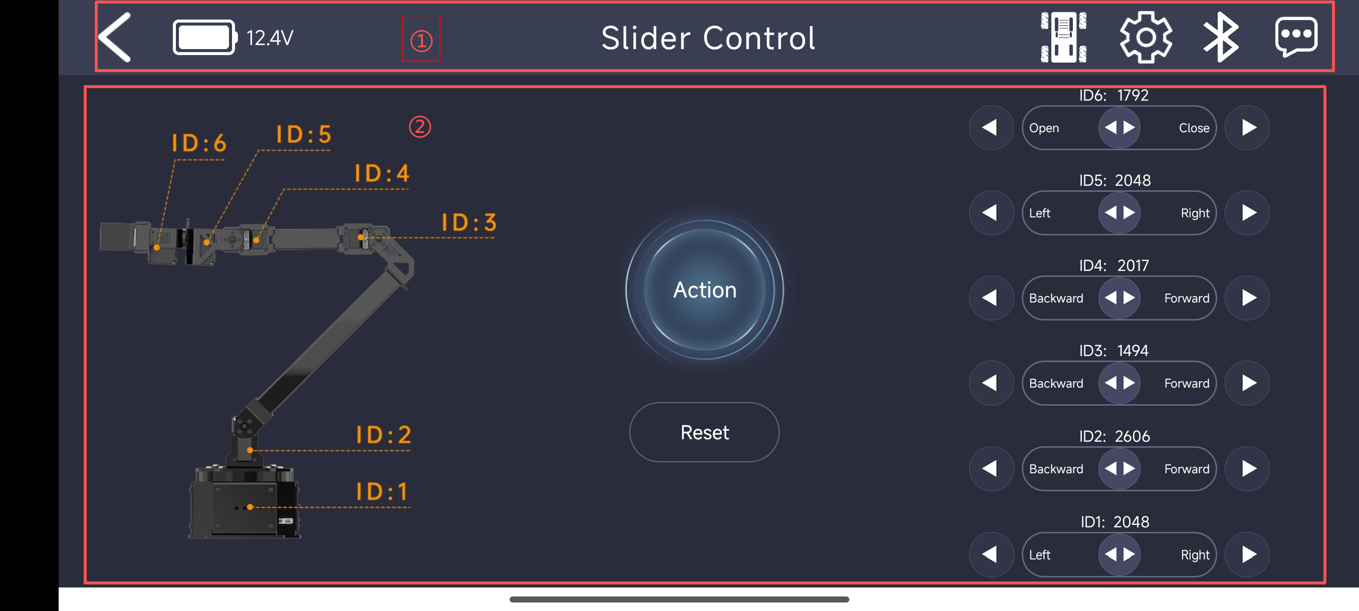
In Slider Control mode, each NexArm servo can be controlled independently by dragging the sliders on the right side. This mode has two main areas, marked as ① the menu bar and ② the control area.
Menu Bar
| Icon | Function Description |
|---|---|
 |
Return to the mode selection screen. |
 |
Display the current NexArm supply voltage in real time. |
 |
Enter the chassis control interface. A mobile chassis is required. |
 |
Bluetooth connection. The icon flashes when disconnected and stays on after connection. |
 |
ESP-NOW mode configuration. A synchronizer is required. |
 |
More information. |
Control Area
| Icon | Function Description |
|---|---|
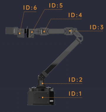 |
NexArm servo ID diagram. |
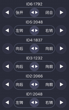 |
Slider for individual servo control. |
 |
Custom action group. The action group must be downloaded to NexArm from the host software in advance. |
 |
NexArm reset button. After pressing it, NexArm enters the reset posture for Slider Control mode. |
Coordinate Control Mode
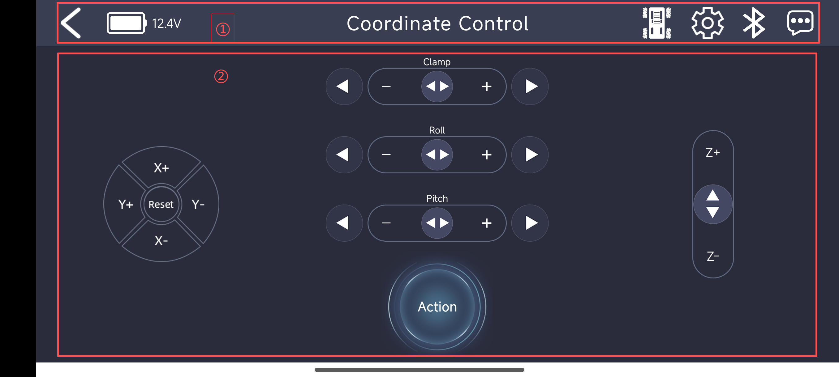
In Coordinate Control mode, NexArm can perform inverse kinematics motion by adjusting the X, Y, Z coordinate buttons and the Roll and Pitch angle sliders. The Clamp slider controls the opening and closing of the gripper. This mode has two main areas, marked as ① the menu bar and ② the control area.
Menu Bar
| Icon | Function Description |
|---|---|
|
Return to the mode selection screen. |
|
Display the current NexArm supply voltage in real time. |
|
Enter the chassis control interface. A mobile chassis is required. |
|
Bluetooth connection. The icon flashes when disconnected and stays on after connection. |
|
ESP-NOW mode configuration. A synchronizer is required. |
|
More information. |
Control Area
| Icon | Function Description |
|---|---|
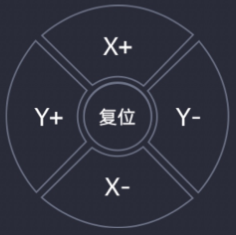 |
X-axis and Y-axis motion buttons for moving NexArm along the X and Y axes and performing reset operations. |
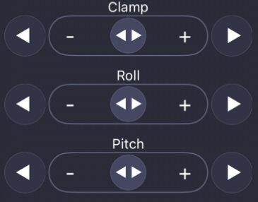 |
The Clamp slider controls gripper opening and closing. The Roll and Pitch angle sliders control inverse kinematics motion. |
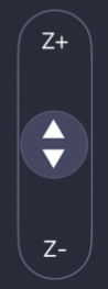 |
Z-axis motion slider for moving NexArm along the Z axis. |
|
Custom action group. The action group must be downloaded to NexArm from the host software in advance. |
1.2.4 Calling Action Groups
In either control mode, tap the action group button.
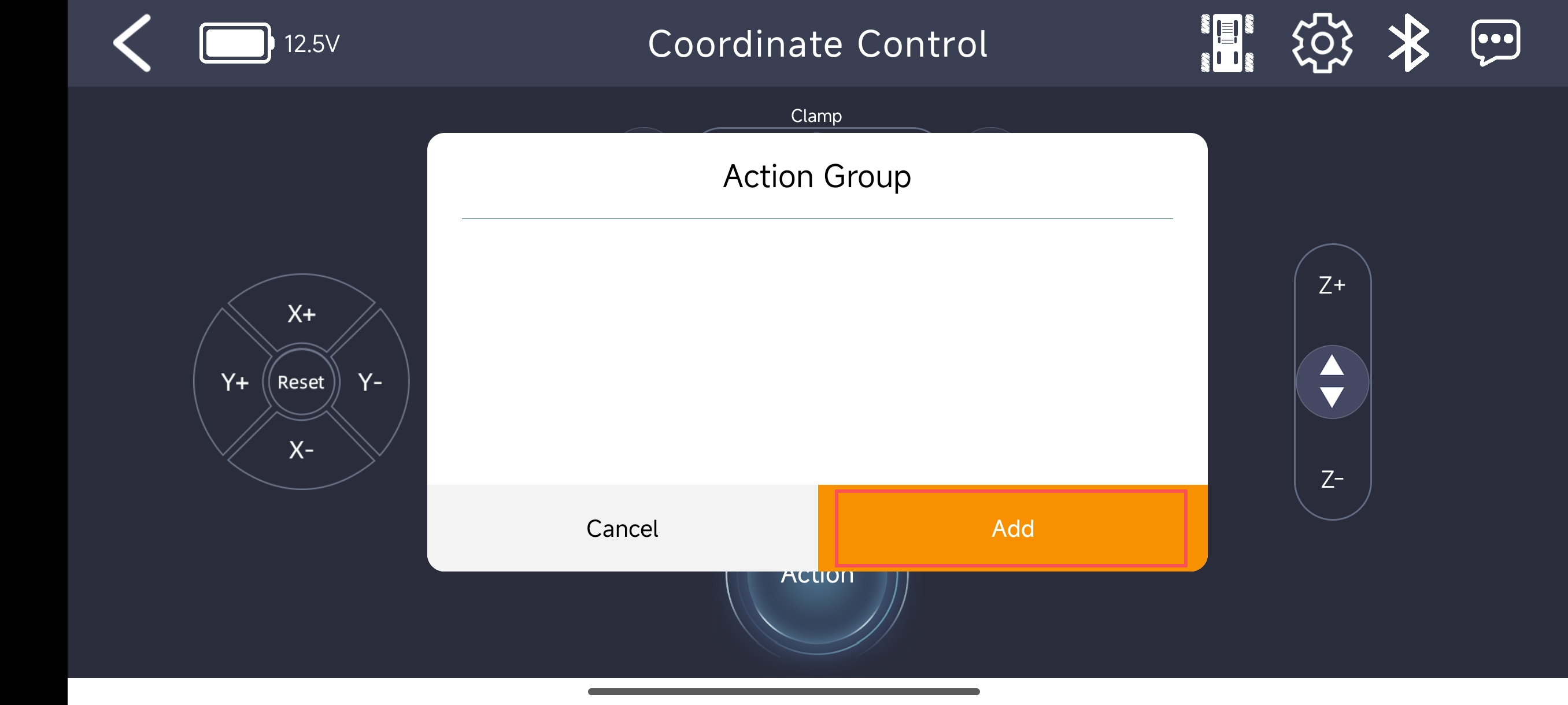
After the button is tapped, the Action Group screen appears. Tap Add to add an action group.
Note
The action group calling function requires the action group ID to be confirmed in the host software in advance, and the action group with the corresponding ID must be downloaded to NexArm. Otherwise, this function cannot be used. For the download procedure, refer to 1.5 Action Group Editing and Execution in this document.
Action group 0 has been downloaded to NexArm from the host software in advance. In this example, the action group is named 111, and the action group ID is set to
0. After the settings are complete, tap OK.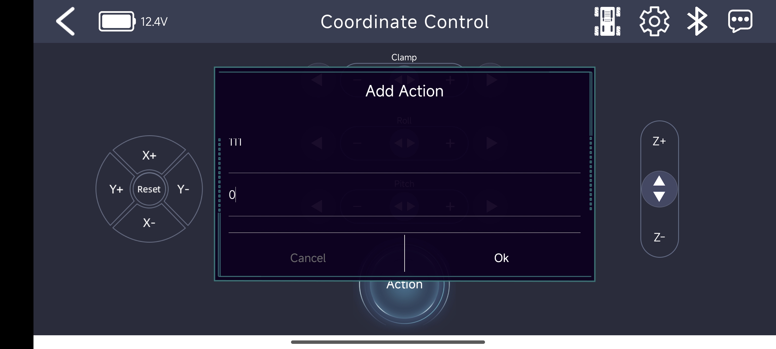
After the information is entered, tap OK. The Add Action window closes, and the
 pop-up appears. Tap the action group button again. The action group named 111 is now shown in the list. Tap it to run the action group with the corresponding ID.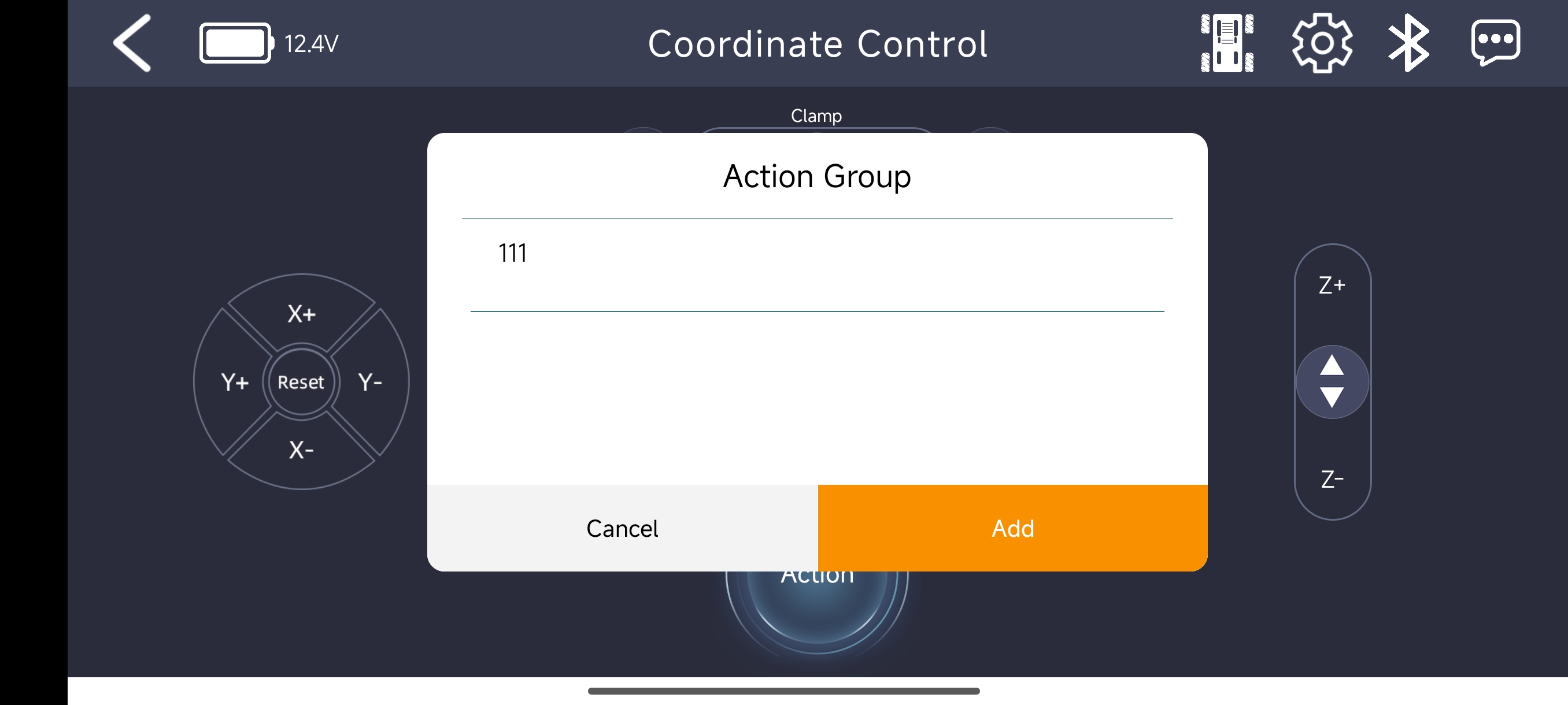
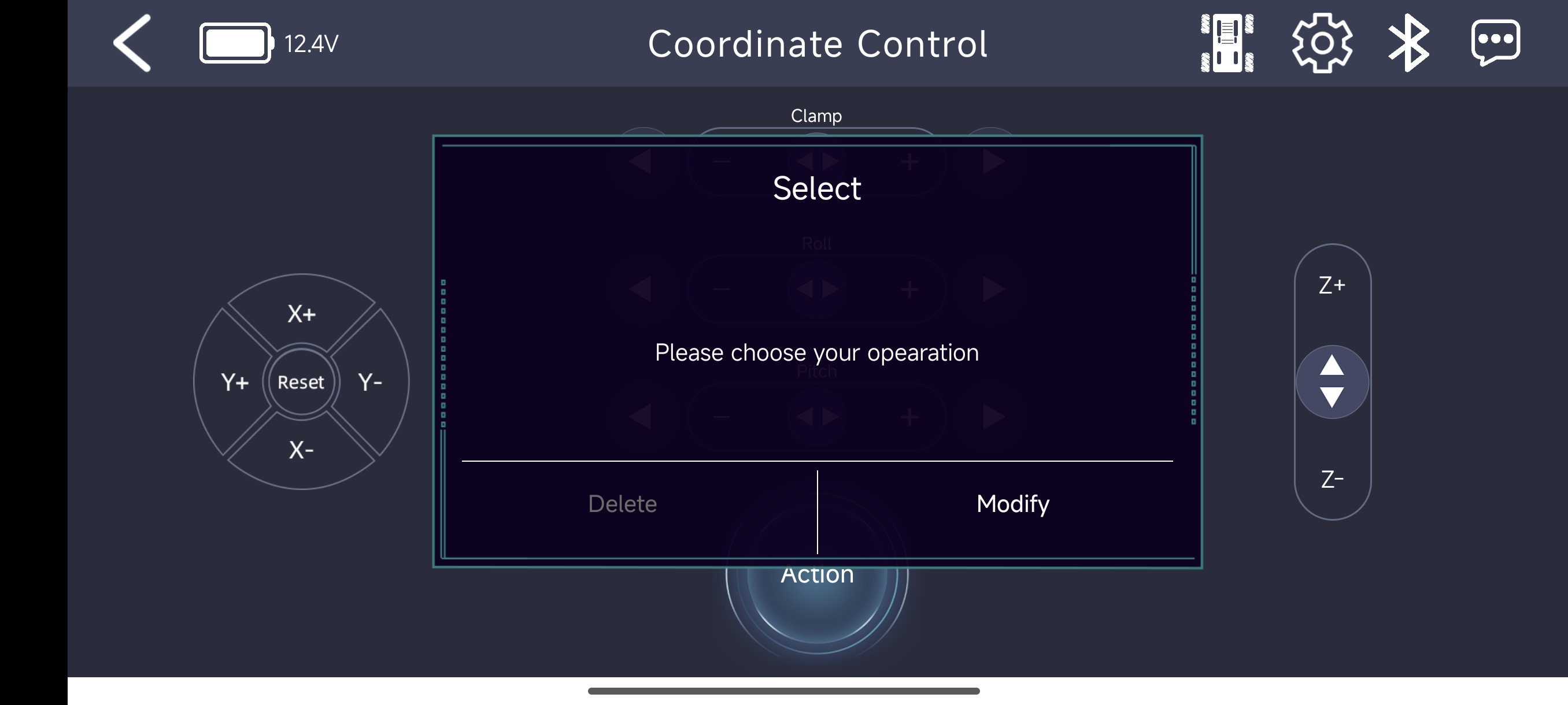
Press and hold the 111 item in the list. The delete and edit options for the action group will appear.
1.3 Wireless Controller Control
1.3.1 PS3 Controller Overview
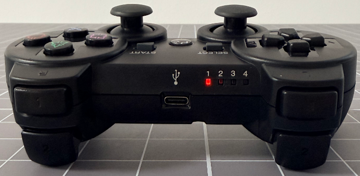
NexArm supports a PS3 protocol-compatible wireless controller for wireless control. The controller is held with both hands. The D-pad is on the left, and the four face buttons △, ○, ×, and □ are on the right. Select and Start are in the center, and the PS button is on the front. The left and right shoulder buttons include L1/L2 and R1/R2, along with two pressable analog sticks, L3/R3. Communication with the main control board is handled through Bluetooth. The controller also includes a built-in battery, USB charging, and player indicator lights. It is used to adjust the robotic arm posture and servos in coordinate control mode and individual servo mode, as well as chassis forward movement, lateral movement, and turning.
1.3.2 Controller Button Layout
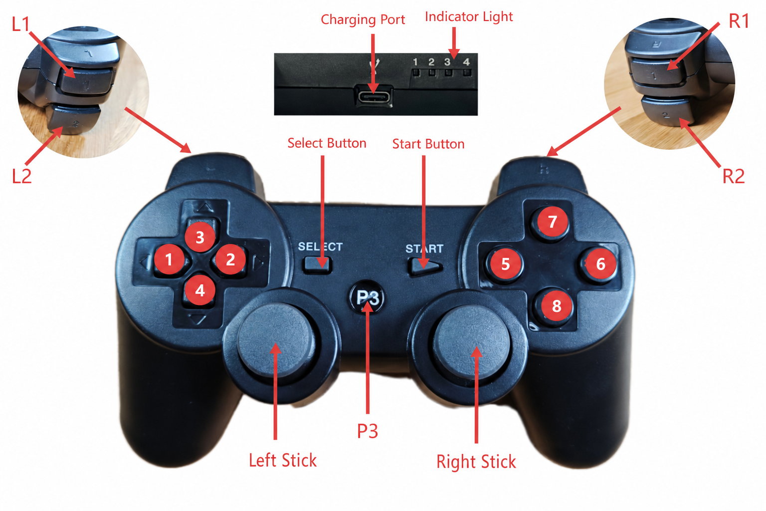
| Button No. | Coordinate Control Mode | Servo Control Mode |
|---|---|---|
| P3 | Power button | Power button |
| Left joystick | Chassis control joystick 1 | Chassis control joystick 1 |
| Right joystick | Chassis control joystick 2 | Chassis control joystick 2 |
| Select button | Press and hold Select and Start at the same time to switch modes. One short beep indicates coordinate control mode. Two short beeps after pressing indicate servo control mode. | Press and hold Select and Start at the same time to switch modes. One short beep indicates coordinate control mode. Two short beeps after pressing indicate servo control mode. |
| Start button | Press once to reset | Press once to reset |
| Charging port | Type-C 5 V charging port | Type-C 5 V charging port |
| Indicator light | After power-on, all four indicator lights flash to show that the controller is searching for a device. After a successful connection, the other indicators turn off, and indicator 1 stays on. | After power-on, all four indicator lights flash to show that the controller is searching for a device. After a successful connection, the other indicators turn off, and indicator 1 stays on. |
| ① | Increase the robotic arm movement along the Y axis | Increase the servo 1 angle |
| ② | Decrease the robotic arm movement along the Y axis | Decrease the servo 1 angle |
| ③ | Increase the robotic arm movement along the X axis | Increase the servo 2 angle |
| ④ | Decrease the robotic arm movement along the X axis | Decrease the servo 2 angle |
| ⑤ | Decrease the robotic arm Pitch angle | Increase the servo 4 angle |
| ⑥ | Increase the robotic arm Pitch angle | Decrease the servo 4 angle |
| ⑦ | Increase the robotic arm movement along the Z axis | Increase the servo 3 angle |
| ⑧ | Decrease the robotic arm movement along the Z axis | Decrease the servo 3 angle |
| L1 | Increase the robotic arm Roll angle | Decrease the servo 5 angle |
| L2 | Decrease the robotic arm Claw angle | Decrease the servo 6 angle |
| R1 | Decrease the robotic arm Roll angle | Increase the servo 5 angle |
| R2 | Increase the robotic arm Claw angle | Increase the servo 6 angle |
1.3.3 Wireless Controller Connection Steps
Check the Bluetooth pairing code on the back of the controller.
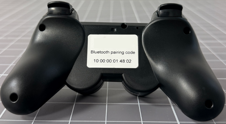
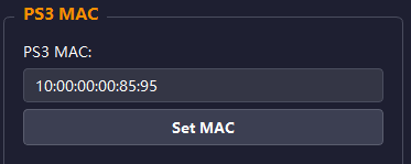
Connect NexArm to the host software, then change the NexArm Bluetooth pairing code to the controller Bluetooth pairing code. For detailed host software connection and usage, refer to 1.4 PC Software Control in this section.
Power on NexArm again. The display will show the NexArm posture information.
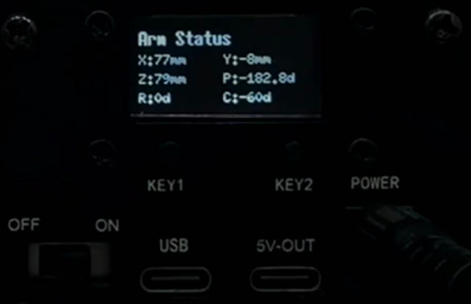
Press key2. The display shows the prompt Switch to BLE Press again to confirm switch.
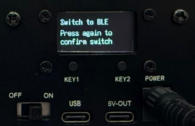
Press key2 again to start switching. After the switch is successful, the screen restarts. The active mode is app Bluetooth control, and the robotic arm can be controlled from the app.
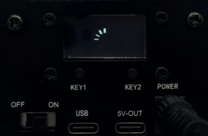
Press key2 again. The display shows the prompt Switch to PS3 Press again to confirm switch.
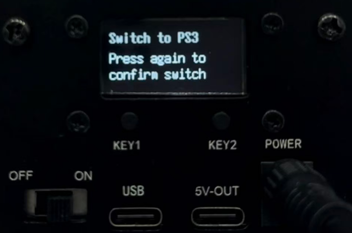
Press key2 again to start switching. After the switch is successful, the screen restarts. Keep NexArm in this state.
Press and hold the controller P3 button. The four indicator lights begin flashing.
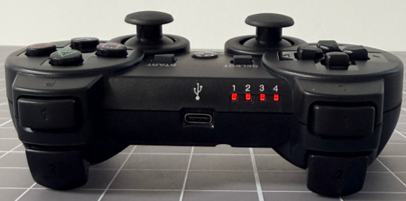
After flashing for 2 to 4 seconds, indicators 2, 3, and 4 stop flashing, and indicator 1 stays on. This indicates that the controller has connected successfully. NexArm can now be controlled according to the controller button descriptions in the next section.
1.4 PC Software Control
1.4.1 PC Software Overview
1.4.1.1 Installing the Serial Port Driver
Double-click ch341ser.exe in 1. Tutorials/1. Getting Started/04 Appendix/03 Serial Port Driver.
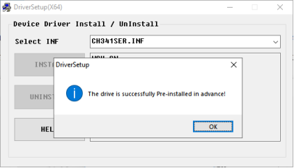
Click INSTALL. After the installation is complete, a driver installation success message will appear.
1.4.1.2 Launching the Software
Note
The PC software does not require installation. Install the driver on the computer before using the software.
Find NexArm.exe in 2. Softwares/1. NexArm PC Software.
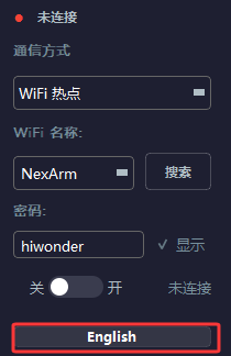
Switch the software language in the lower-left corner based on the required language.
1.4.1.3 Device Connection
Note
NexArm is shipped with the factory program already downloaded, so the robotic arm can be powered on and tested directly. If another program has overwritten the factory program, it can be found in the same directory as this file and downloaded again.
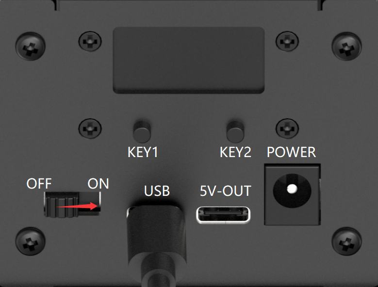
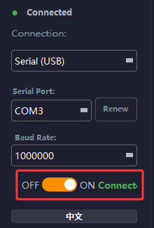
Toggle the switch to ON to turn on the NexArm power switch.
Serial Port Connection
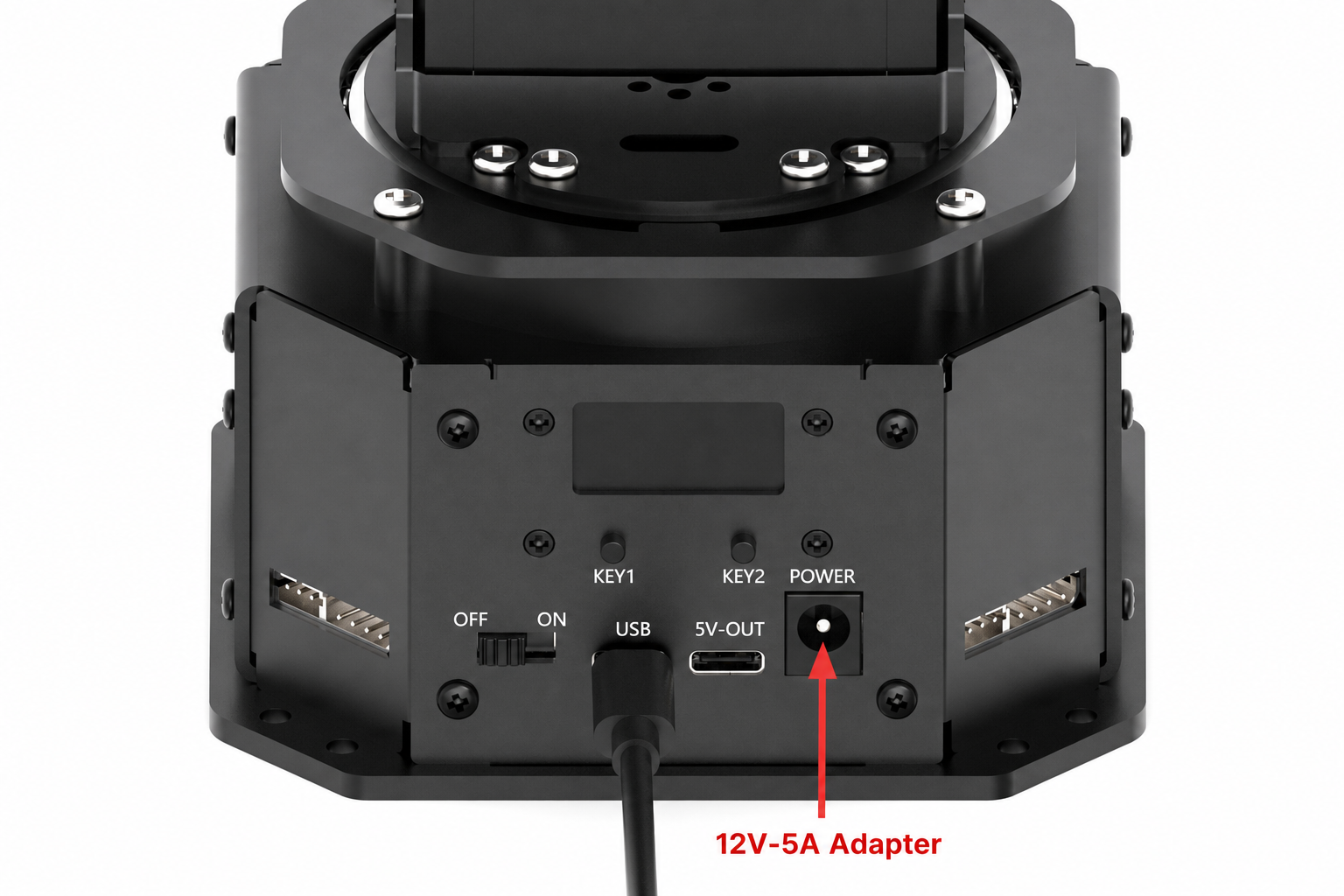
After the robotic arm is powered on, connect NexArm to the computer with a Type-C data cable.
Open the host software, select USB Serial as the communication method, and select the corresponding device port to connect.
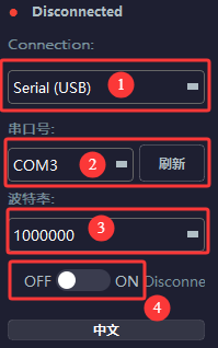
When the red circular icon turns green and shows connected, the connection is successful.
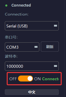
Wi-Fi Connection
After the robotic arm is powered on, press key1 to switch to ESP-NOW mode for synchronizer control.
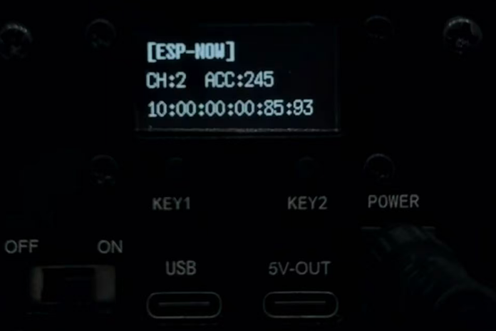
After switching to ESP-NOW mode, press key1 again to switch to WiFi AP mode. The display will show the Wi-Fi name NexArm and the IP address. At this point, the host software can connect wirelessly.
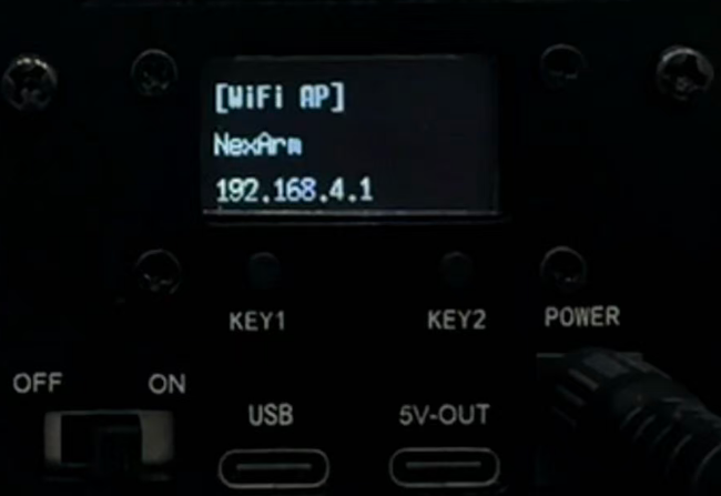
Open the host software, switch the communication method to WiFi Hotspot, search for the NexArm hotspot, and connect to it. The connection password is hiwonder.
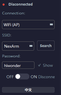
After the connection succeeds, the connected prompt is displayed. At the same time, the device IP field in System Log displays the NexArm IP address. This indicates a successful connection.
1.4.2 Function Overview
The host software communicates with NexArm through six control modes and system settings to implement different functions: Servo and Action Group, Coordinate Control FK/IK, Peripheral Control, System Settings, AI Vision Functions, and Advanced Servo Settings.
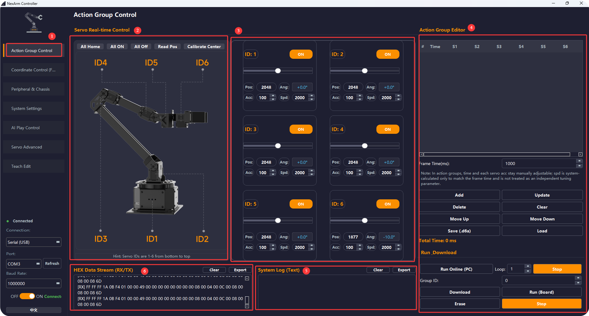
1.4.2.1 Servo and Action Group
| Label | Area Name | Purpose and Function | How to Use |
|---|---|---|---|
| 1 | Action Group Control tab entry | Opens the main Action Group Control page. This page is used for individual servo debugging, action group editing, action group download, and action group execution. | Click the left-side menu to enter this page. Complete the serial port connection first. |
| 2 | Real-time servo control and robotic arm diagram area | Displays the position relationship of the 6 servos on the robotic arm and provides whole-arm buttons: All Home, All On, All Off, Read Pos, and Calibration Center. All Home returns the whole arm to the default posture. All On and All Off enable or disable torque for the whole arm. Read Pos refreshes the current servo status. The Calibration Center is mainly used for installation and calibration, usually to adjust servos to the mechanical installation reference center. | Before debugging, click All On, then click Read Pos. Click All Home when the robotic arm needs to return to a safe posture. Use the Calibration Center during horn installation or zero-position calibration. This sets the current angles of all servos as center angles, except servos 5 and 6. |
| 3 | Individual servo control card area | Each ID has an independent control card, including ON/OFF, a position slider, Pos, Ang, Acc, and Spd. This area is used for independent debugging and fine adjustment of individual joints. | Select the corresponding ID, turn ON on, then adjust the position through the slider or value box. Acc controls the acceleration of the current motion, and Spd controls the speed of the current motion. When a single axis behaves abnormally, check each axis one by one. |
| 4 | Action group editing and running area | Used to edit, save, load, download, and run action groups. The upper table saves Time + S1~S6 by frame. A single-frame time can be set in the middle area. The middle-lower area provides Add, Update, Delete, Clear, Move Up, Move Down, Save .d6a, and Load. The bottom area provides Run Online (PC), loop count, Group ID, Download, Run (Board), Erase, and Stop. Download writes the action group to the ESP32. During onboard execution, the controller runs the onboard file by group ID. |
Common workflow: 1. Manually adjust the posture. 2. Click Add to record one frame. 3. Repeat until the full action is recorded. 4. Save it locally as a .d6a file. 5. To run offline, set the Group ID, then click Download. 6. Click Run (Board) to let the controller execute the action independently. During online debugging, Run Online (PC) can be used directly. |
| 5 | System Log | Displays connection status, action group operation results, error prompts, and function feedback for checking whether commands execute correctly. | Check this area first when running action groups, downloading files, or stopping actions. If the log is empty or abnormal, check together with the HEX data stream. |
| 6 | HEX data stream RX/TX | Displays raw hexadecimal communication data between the host software and controller. It is suitable for protocol debugging and serial communication troubleshooting. | After a function button is clicked, check this area first to confirm whether corresponding transmit or receive data appears when commands or responses seem missing. |
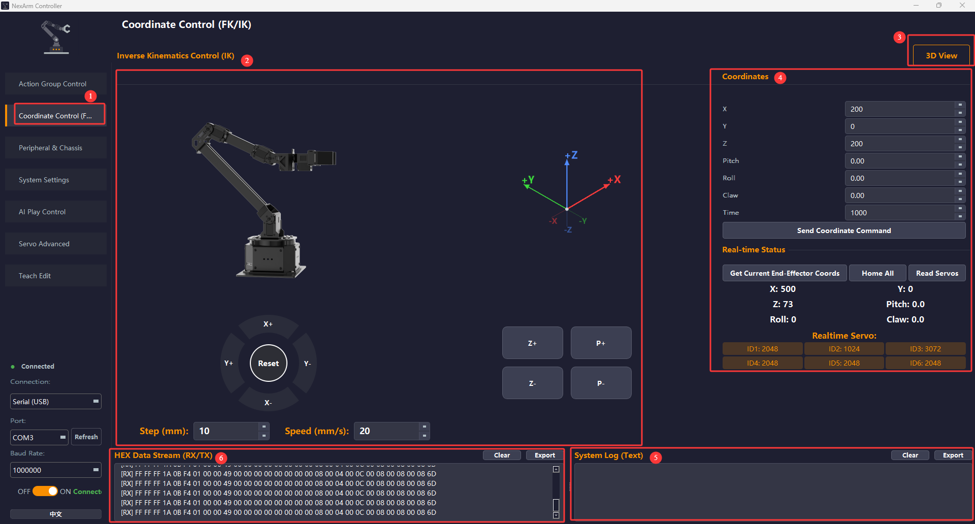
1.4.2.2 Coordinate Control
| Label | Area Name | Purpose and Function | How to Use |
|---|---|---|---|
| 1 | Coordinate Control FK/IK tab entry | Opens the coordinate control page. This page mainly controls the robotic arm by end-effector coordinates instead of individual servo angles. | Click the left-side menu to enter this page. |
| 2 | Inverse kinematics control main area | Provides the end-effector incremental control area, including X+, X-, Y+, Y-, Z+, Z-, P+, P-, and Reset, and displays the robotic arm posture diagram and coordinate axis directions. Step mm sets the movement step for each click. |
To fine-tune the end-effector position, set Step mm first, then click the direction buttons to approach the target position step by step. P+ and P- mainly adjust the pitch angle, and Reset returns to the default reference posture in this area. |
| 3 | 3D view button | Switches or opens the 3D posture view to help observe coordinate axis directions, end-effector posture, and spatial relationships. This area is mainly for visualization and is not a low-level control command. | Click it when a more intuitive posture view is needed. If a separate 3D window is not enabled in the current software version, this button is usually still kept as a posture-view entry. |
| 4 | Coordinate parameters and the real-time status area | Allows direct input of X, Y, Z, Pitch, Roll, Claw, and Time, then sends the full coordinate set. It also supports Get Current End Coordinate, Center All, and Read Servo. The lower area displays the current TCP status and real-time values of all 6 servos. |
When target coordinates are known, enter the target values and click Send Coordinate Command. To read the current posture first and then make a small adjustment, click Get Current End-Effector Coords. To check joint status, click Read Servos. |
| 5 | System Log | Displays text feedback for coordinate control, status reading, centering, and communication exceptions. | Check this area first when no motion occurs during coordinate control. |
| 6 | HEX data stream RX/TX | Displays coordinate control commands and returned packets, including sending coordinates, reading servos, and reading end-effector coordinates. | Used to confirm whether IK control commands have been sent to the device. |
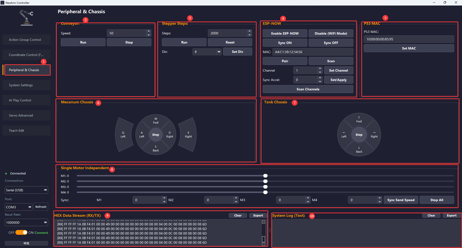
1.4.2.3 Peripheral Control
| Label | Area Name | Purpose and Function | How to Use |
|---|---|---|---|
| 1 | Peripheral Control tab entry | Opens the peripheral control page. This page centrally manages the conveyor belt, slide rail, ESP-NOW, PS3 MAC, chassis, and multiple motors. |
Click the left-side menu to enter this page. |
| 2 | Conveyor Belt | Sets the conveyor belt speed and controls run and stop. It corresponds to CMD_CONVEYOR_SET in the firmware. |
Enter a value in the speed box, then click Run to start. Click Stop to stop. This is commonly used when debugging grasping or sorting scenarios. |
| 3 | Slide rail steps | Controls the step count, reset, and microstepping settings of the stepper slide rail. It corresponds to CMD_STEPPER_RUN, CMD_STEPPER_RESET, and CMD_STEPPER_DIV in the firmware. |
Set the target step count first, then click Run. Click Reset to return to the origin. To adjust motion resolution, set Div, then click Set Div. |
| 4 | ESP-NOW | Configures ESP-NOW wireless mode, synchronization switch, target MAC, channel, and synchronization acceleration. It also supports channel scanning. |
Common workflow: 1. Click Enable ESP-NOW. 2. Configure the target MAC or pairing. 3. Set Channel. 4. Click Sync On when Leader-Follower synchronization is required. 5. If interference is heavy, click Scan Channels first, then select a cleaner channel. |
| 5 | PS3 MAC | Writes the PS3 controller Bluetooth MAC address. After receiving this command, the firmware saves the configuration and restarts to apply the new MAC. | Enter the correct PS3 MAC and click Set MAC. A brief device disconnection after setting is normal because the device restarts. |
| 6 | Mecanum chassis | Controls the Mecanum chassis to move forward, move backward, strafe left, strafe right, turn left, turn right, and stop. It applies to omnidirectional chassis. | Use this area when the device chassis type is Mecanum. Click the corresponding direction button to test chassis movement. If movement is abnormal, check whether the chassis parameters in System Settings are correct. |
| 7 | Tracked chassis | Controls the tracked or differential chassis to move forward, move backward, turn left, turn right, and stop. | Use this area when the device uses a tracked or differential chassis. Low-speed direction testing is recommended first. |
| 8 | Individual motor control | Independently controls motors M1~M4, and can also send four speed values at the same time. It is suitable for correcting individual motor direction, troubleshooting motor faults, or testing combined drive motion. |
During individual checks, adjust the upper sliders. To send all four values together, enter M1~M4 values below, then click Sync Send Speed. Click Stop All for emergency stop. |
| 9 | HEX data stream RX/TX | Displays low-level commands sent from the peripheral control page. It is especially useful for checking whether ESP-NOW, chassis, and motor commands are actually sent. |
If a peripheral does not respond, check this area first to see whether packets are being sent. |
| 10 | System Log (Text) | Displays status feedback and error information during peripheral control. | If peripheral motion does not match expectations, check this area together with the HEX area first. |
1.4.2.4 System Settings
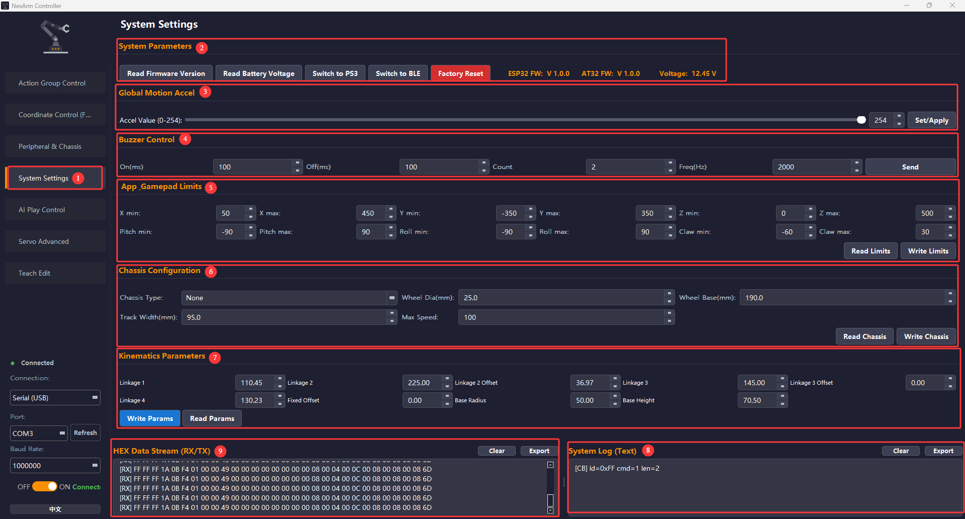
| Label | Area Name | Purpose and Function | How to Use |
|---|---|---|---|
| 1 | System Settings tab entry | Opens the system settings page. This page is mainly used for reading system parameters, restoring factory settings, setting limits, global acceleration, buzzer control, and chassis parameters. | Click the left-side menu to enter this page. |
| 2 | System parameters | Includes Read Firmware Version, Read Battery Voltage, Switch to PS3, Switch to BLE, and Factory Reset. Restore Factory Settings resets coordinate limits, servo offsets, additional motion acceleration, robotic arm posture, chassis parameters, kinematics parameters, and the default PS3 MAC. | Use Factory Reset during device delivery, maintenance, or when parameters become disordered. The device restarts after switching BLE or PS3 mode, which is normal. |
| 3 | Global motion acceleration | Sets the global acceleration parameter, which affects synchronized individual servo motion, ESP-NOW synchronization, and some motion control functions. It corresponds to CMD_SET_GLOBAL_ACC in the firmware. |
Lower the value if motion feels too abrupt. Increase it appropriately if motion feels too sluggish, then click Set/Apply. |
| 4 | Buzzer control | Sets on duration, off duration, count, and frequency, then sends a buzzer prompt command for debugging or interaction feedback. It corresponds to CMD_BUZZER_SET in the firmware. |
Enter the parameters, then click Send to test whether the buzzer works properly or to create an interaction prompt. |
| 5 | App and controller limits | Sets the upper and lower limits for X, Y, Z, Pitch, Roll, and Claw. These parameters affect coordinate control and controller control ranges and act as safety boundaries. The firmware updates the local ESP32 variables and sends the limits to AT32. |
Click Read Limits to check the current configuration, then make small adjustments and click Write Limits. After changes are made, test the boundary movement immediately to confirm that no limit is exceeded. |
| 6 | Chassis parameter settings | Sets chassis type, wheel diameter, wheelbase, track width, maximum speed, and related parameters. It corresponds to CMD_SET_CHASSIS_CONFIG and CMD_GET_CHASSIS_CONFIG in the firmware. |
Read and modify parameters here after replacing the chassis or when chassis movement is inaccurate. After parameters are written, verify movement immediately on the Peripheral & Chassis page. |
| 7 | Kinematics parameter settings | Configures 9 floating-point parameters for the robotic arm geometry model: link 1, link 2, link 3, link 4, link 2 offset, link 3 offset, fixed offset, base radius, and base height. The unit is generally mm, and the parameters are used for FK/IK. |
Click Read Params first to check the current lower-controller configuration. Modify the input boxes as needed, then click Write Params to save and send the parameters. After replacing links or structural parts, calibrate the full parameter set. After writing, perform a simple point-to-point motion to verify end-effector accuracy. |
| 8 | System Log (Text) | Displays execution feedback for system settings, such as version reading, voltage reading, limit writing, and factory reset results. | Pay close attention to this area when operating system-level parameters. |
| 9 | HEX data stream RX/TX | Displays low-level protocol data related to system settings. | Use this area to confirm protocol communication when limit writing, Bluetooth mode switching, or chassis parameter settings do not take effect. |
1.4.2.5 AI Vision Functions
Note
AI vision functions require the K230 vision module. Before enabling AI vision functions, the latest image must be flashed to the K230 vision module. The image is located under 2. Softwares/6. WonderMK K230 Vision Module Manual & Tool/04 K230 Vision Module Image. For the image flashing procedure, refer to 2. Softwares/6. WonderMK K230 Vision Module Manual & Tool/01 K230 Vision Module Manual/1. Quick Start.pdf.
Vision Offset Calibration
Note
Vision offset calibration must be performed before enabling AI vision functions. The AprilTag cards required for vision offset calibration are located under 2. Softwares/7. E-Card Collection/02 AprilTag Cards.
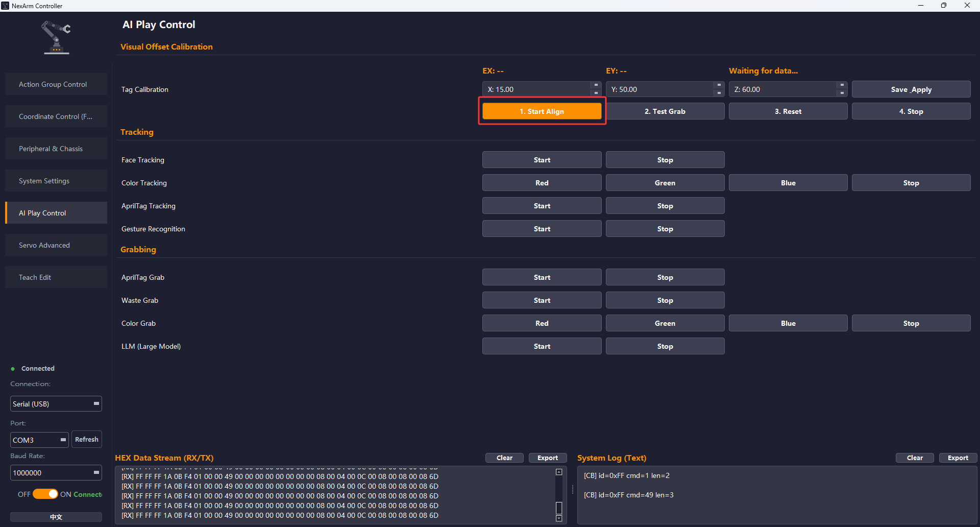
Place the AprilTag card on the desktop, then click 1. Start Align. The robotic arm moves to the calibration posture, and the System Log prints the AprilTag debugging information.
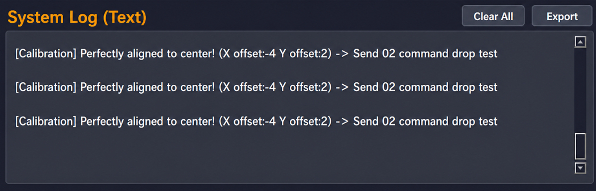
Move the AprilTag card according to the debugging information until the System Log prints Perfectly aligned to center!, as shown below.
Click 2. Test Grab. The robotic arm lowers into the grasping posture.

If the robotic arm does not reach the expected angle after lowering, click 3. Reset first, then adjust the
X,Y, andZvalues. After the adjustment is complete, click Save_Apply, then click 2. Test Grab again. Repeat until the robotic arm reaches the expected position after lowering. After the expected position is reached, click 4. Stop.
Note
If the robotic arm shifts left or right after lowering, adjust the
Yvalue.If the robotic arm shifts forward or backward, adjust the
Xvalue.If the robotic arm shifts up or down, adjust the
Zvalue.

Tracking Functions
Click Start to start the corresponding function. After the function is enabled, the robotic arm performs tracking motion based on the recognized target.
AprilTag Automatic Grasping
Place the AprilTag card on the desktop. After Start is clicked, the robotic arm automatically recognizes the target, adjusts its angle, lowers, and grasps the target.
Waste Sorting Grasping
This function works similarly to AprilTag Automatic Grasping. After Start is clicked, the robotic arm automatically recognizes the target, adjusts its angle, lowers, and grasps the target. The waste sorting electronic cards are located under 2. Softwares/7. E-Card Collection/03 Waste Classification Cards.
Large AI Model Functions
Before using the large AI model functions, flash the image and configure the network connection and large AI model by following 2. Softwares/6. WonderMK K230 Vision Module Manual & Tool/01 K230 Vision Module Manual/1. Quick Start.pdf and 2. Softwares/6. WonderMK K230 Vision Module Manual & Tool/01 K230 Vision Module Manual/2. Large AI Model Configuration and Usage.
After the network is configured, open the AI Model function on the K230 vision module and wake it up with the voice command Hello Hiwonder.
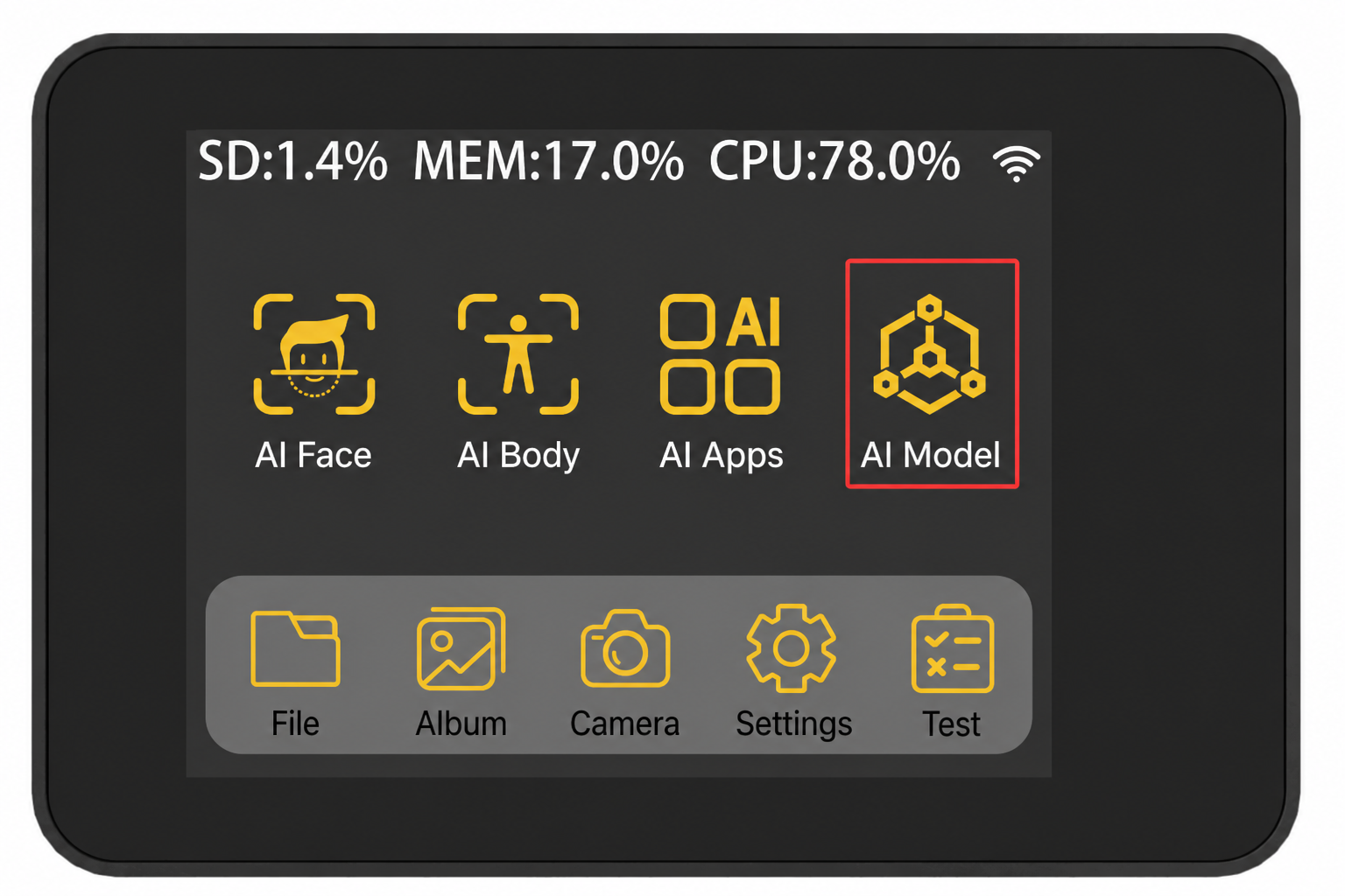
After waking up, click Start in the large AI model function of the host software, then issue commands to control the robotic arm to perform the corresponding actions.

1.4.2.6 Advanced Servo Settings
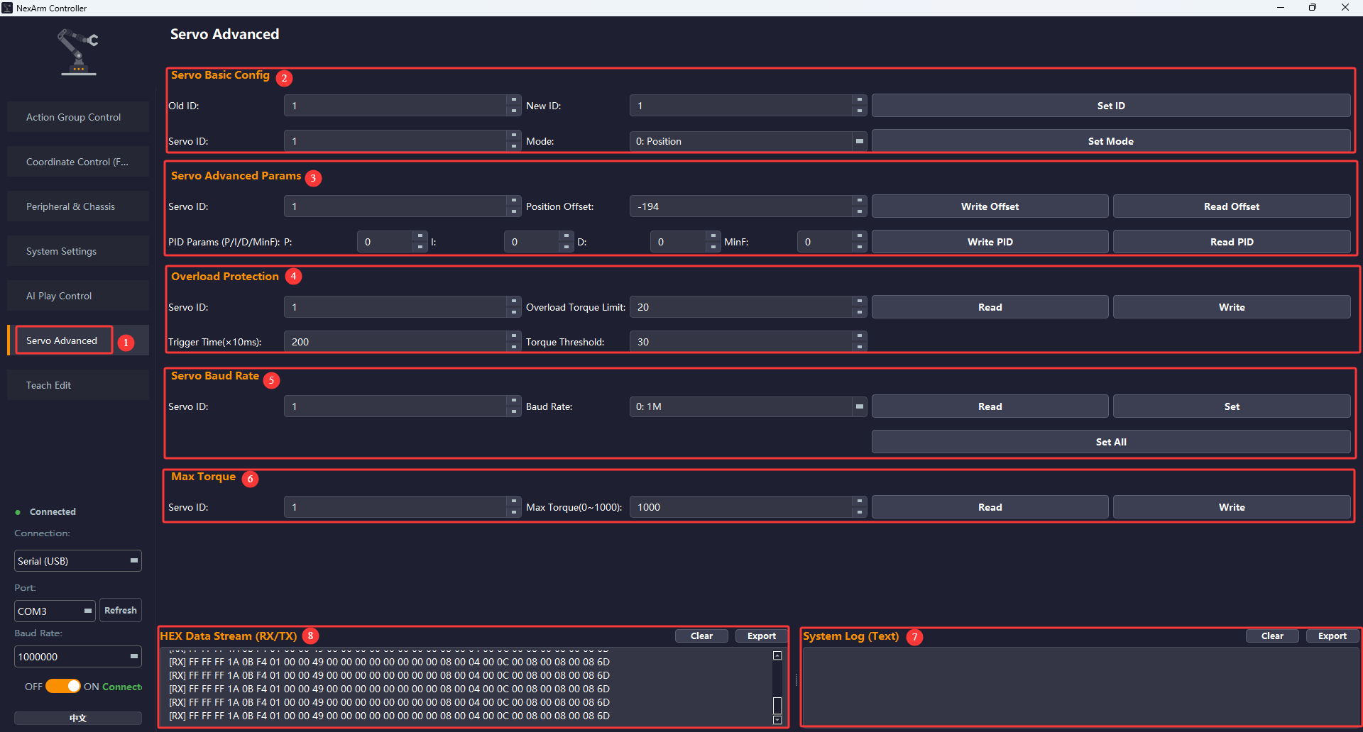
| Label | Area Name | Purpose and Function | How to Use |
|---|---|---|---|
| 1 | Advanced Servo Settings tab entry | Opens the low-level servo parameter configuration page. This page is mainly used for advanced parameters such as servo ID, mode, offset, PID, overload protection, baud rate, and maximum torque. | Click the left-side menu to enter this page. |
| 2 | Basic servo settings | Provides ID modification from Old ID to New ID, and sets the working mode by servo ID. The example mode in the screenshot is 0: Position mode. | When changing an ID, it is recommended to keep only one target servo on the bus to avoid changing the wrong servo. After the mode is changed, test immediately whether the position control still responds normally. |
| 3 | Advanced servo parameters | Includes reading and writing position Offset and reading and writing PID Parameters (P/I/D/MinF). Offset and PID commands in the firmware are directly passed through to the low-level AT32. | Common workflow: 1. Read the offset or PID first. 2. Make a small adjustment. 3. Write the parameter back to the device. 4. Verify with motion testing. |
| 4 | Overload protection | Sets overload limit torque, trigger time, and torque threshold, and supports reading and writing. This protects the servo from excessive force when it stalls, gets stuck, or experiences impact loads. | When the robotic arm carries a heavy load or is likely to get stuck, the threshold can be lowered appropriately for protection. Low-speed testing should be performed immediately after modification. |
| 5 | Servo baud rate | Reads and sets the baud rate of a single servo, and also supports Set All. | The bus baud rate must match the controller communication setting. An incorrect baud rate may cause the servo to temporarily go offline, so it is recommended to test a single servo successfully before applying settings in a batch. |
| 6 | Maximum torque | Reads and writes the maximum servo torque limit. The example range is 0~1000. |
Increase it appropriately when the gripper slips or a joint lacks force. Lower it appropriately when the mechanical structure is fragile or during debugging. |
| 7 | System Log (Text) | Displays execution results and error information for advanced setting commands. | After low-level servo parameters are changed, check this area to confirm whether writing succeeded. |
| 8 | HEX data stream RX/TX | Displays low-level protocol data related to advanced servo settings. | Used to determine whether the PC software failed to send data or the lower controller failed to respond when the baud rate, offset, PID, or other parameters fail to write. |
1.4.2.7 Teach Edit
Function Entry
Click Teach Edit in the left-side menu to enter the corresponding interface.
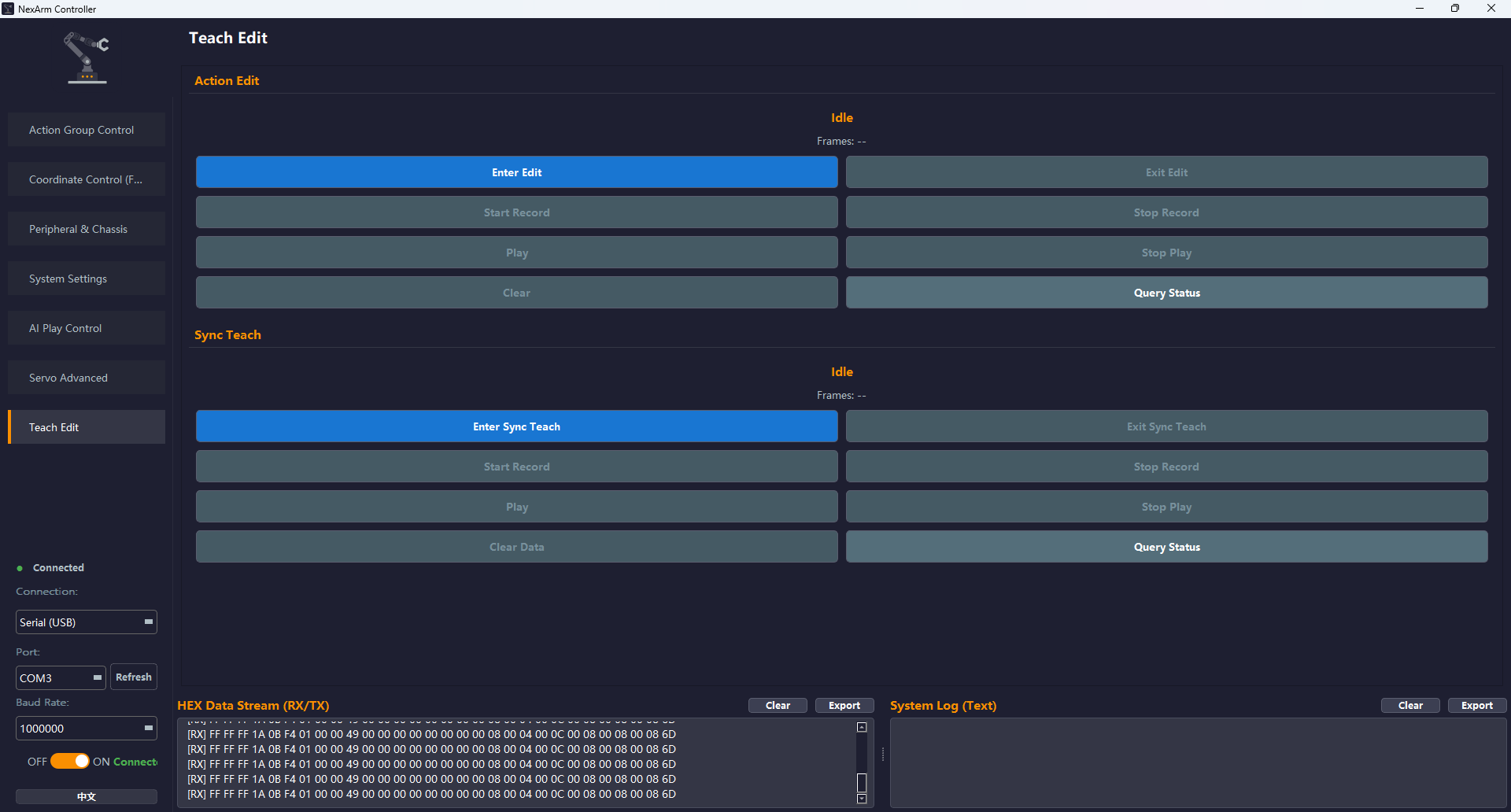
Action Edit Steps
Click Enter Edit. All NexArm servos power off, and any servo can be moved by hand.
After clicking Start Record, move any servo by hand. The system records the motion automatically.
Click Stop Record. The system stops recording the current action automatically and saves the recorded action.
Click Play. NexArm automatically executes the action recorded in step 2 and stops automatically after playback is complete.
Click Stop Play to interrupt an action that is currently playing.
Click Clear to clear the recorded action.
Click Query Status to print information such as the current playback frame count in the system log.
Click Exit Edit. All NexArm servos power on, and Action Edit mode exits.
Sync Teach Steps
Power on the synchronizer normally.
Click Enter Sync Teach. NexArm automatically connects to the synchronizer and synchronizes motion.
After clicking Start Record, operate the synchronizer. NexArm automatically performs the same motion and records and saves the current motion.
Click Stop Record. The system stops recording the current action automatically and saves the recorded action.
Click Play. NexArm automatically executes the action recorded in step 2 and stops automatically after playback is complete.
Click Stop Play to interrupt an action that is currently playing.
Click Clear Data to clear the recorded action.
Click Query Status to print information such as the current playback frame count in the system log.
Click Exit Sync Teach. All NexArm servos power on, and Sync Teach mode exits.
1.5 Action Group Editing and Execution
1.5.1 Editing an Action Group
After the robotic arm is connected to the PC software, switch to the Action Group Control interface and click Read Pos.
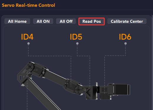
After the position is read, the current position of each ID is displayed in real time on the right.
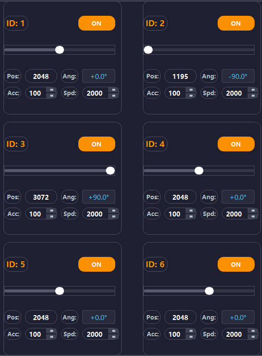
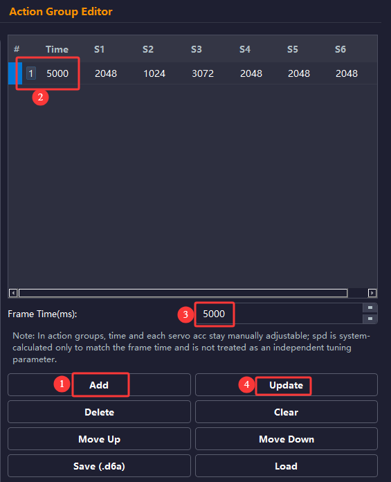
Click Add in the Action Group Editor section to add the current angles of all servos as one action frame. Click the action group number to run this frame. After selecting the number, modify the value of the Frame Time(ms), then click Update to set the time required to run this frame in the action group.
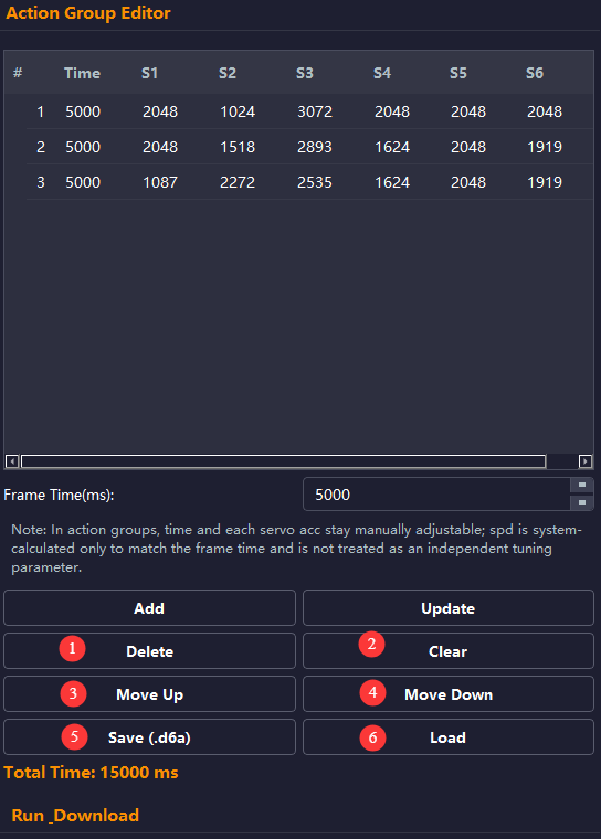
When editing a multi-frame action group, select an action group number and click Delete to delete the corresponding frame. Click Clear to delete and clear all actions. After an action is selected, click Move Up or Move Down to adjust the position of that frame. Click Save (.d6a) to save the current action group as a .d6a file. Click Load to parse a .d6a file into an action group and import it into NexArm.
Factory preset action groups are provided under 1. Tutorials/1. Getting Started/04 Appendix/04 Factory Action Groups. They can be flashed to NexArm by following the method above.
1.5.2 Running and Downloading an Action Group
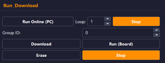
After the action group is edited, click Run Online (PC) in the Run_Download section to run all edited action groups. After modifying the Group ID, which is the action group number, click Download to download the current action group to the robotic arm controller. Click Run (Board) to run the action group downloaded to the robotic arm controller. Click Erase to delete all action groups downloaded to the controller. Stop stops the action group that is currently running.
1.6 Synchronizer Control
Press key1 to set NexArm to ESP-NOW mode.
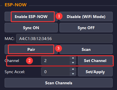
The Peripheral & Chassis page in the PC software can also be used. Click Enable ESP-NOW, change the channel to 2, click Set Channel, and finally click Pair. To control multiple NexArm units with the synchronizer, click Scan.
After the mode is switched successfully, power on the synchronizer. NexArm automatically pairs with the synchronizer. The synchronizer can control NexArm in real time for synchronized motion.