2. ESP32 Development Basics
2.1 ESP32 Development Environment Configuration
2.1.1 Arduino IDE Installation
Arduino IDE is a powerful software application specifically designed for Arduino microcontrollers. The installation process is identical for all versions. This section uses the Windows version of Arduino 2.2.1 as an example for demonstration.
Note
The installation method for macOS can be found in the directory of this section.
Locate the installation package named ArduinoIDE-2.2.1.exe in the folder 02 Program Source Code\01 Arduino Installation Package and Development Package under the same directory of this document, and double-click to open it. To download the latest version of the software, visit the Arduino Official Website.
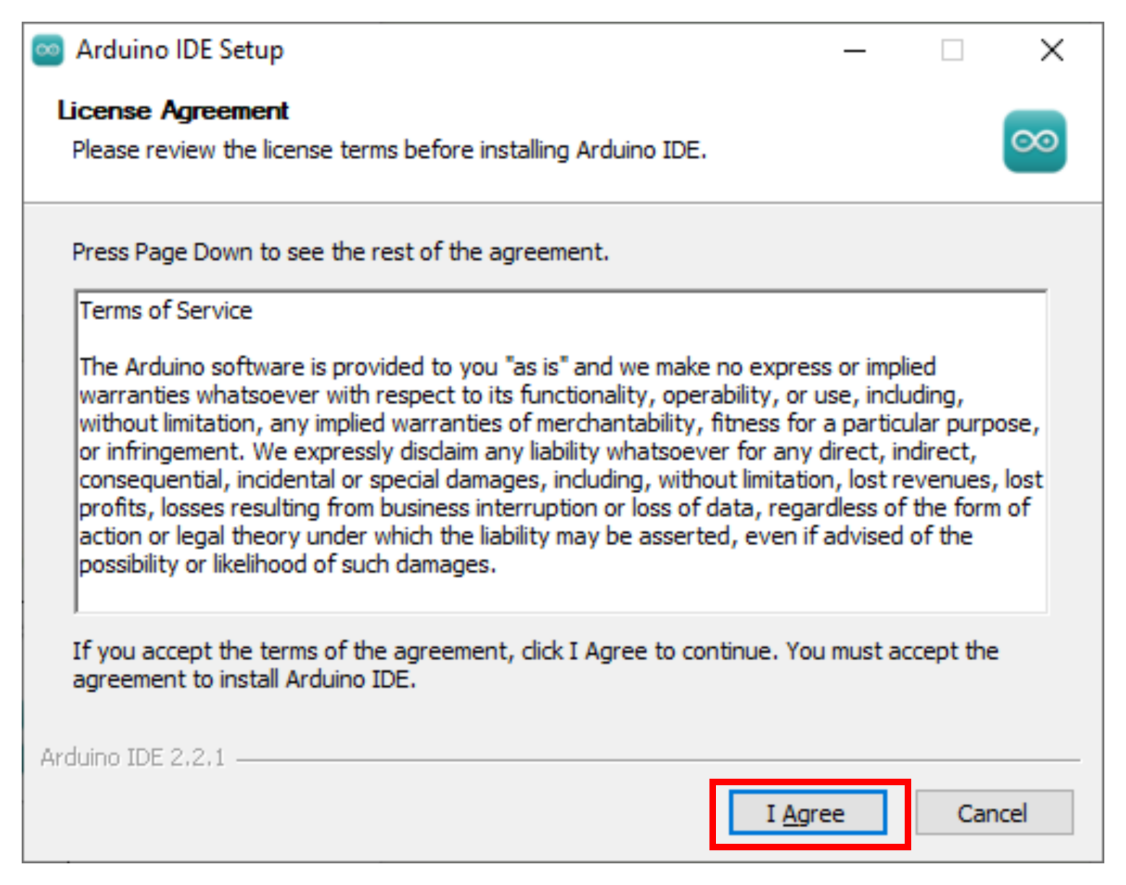
Click I Agree to proceed with the installation.
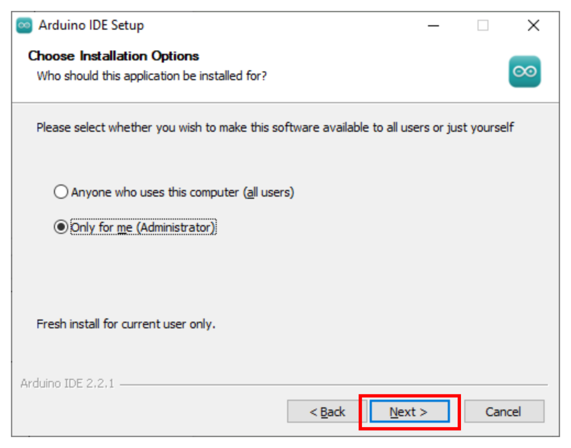
Keep the default selected options, then click Next to proceed to the next step.
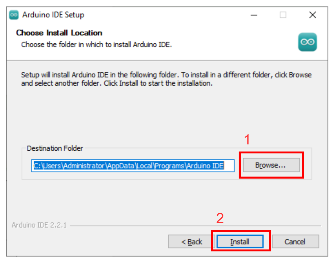
Click Browse to select the installation path, and then click Install to start the installation.
Wait for the software installation to complete.
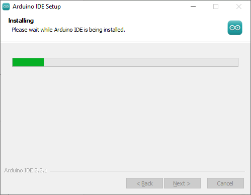
Note
If prompted to install the chip driver during the installation process, check the option to always trust software from Arduino LLC and then click Install.
Once the installation is complete, click Finish.
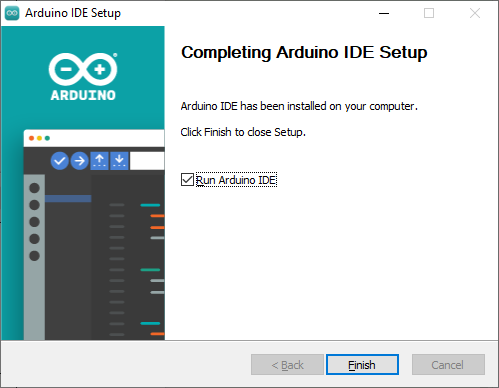
2.1.2 Interface Layout Introduction
The main interface of Arduino IDE is shown in the figure below, which can be divided into five areas.
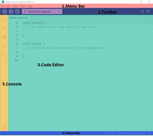
Menu Bar: Responsible for Arduino IDE related settings.
| Icon | Function |
|---|---|
 |
Allows creating or opening project files and configuring interface preferences. |
 |
Provides editing options to perform text editing tasks such as code commenting, indentation, and searching. |
 |
Provides project options to configure the entire project, including compilation, execution, and adding library files. |
 |
Provides tool options to select the development board and port, and retrieve board information. |
 |
Provides help options to assist with getting started and troubleshooting common issues. |
Toolbar: Project-related tools, including compiling programs, uploading programs, and opening the serial monitor.
| Icon | Function |
|---|---|
 |
Verify. Checks if a program is written correctly and compiles the project if there are no errors. |
 |
Upload. Uploads the program to the Arduino controller. |
 |
Debug. Real-time debugging is supported for some development boards via Arduino IDE. |
 |
Select Board. Allows selecting different development boards for project development. |
 |
Serial Plotter. Plots the data printed to the Arduino serial port into a chart. |
 |
Serial Monitor. Prints serial port information. |
Editor Area: The area for writing and editing code.
Status Bar: Displays the current status of the editor, such as code line and column numbers, and development board information.
Sidebar: The core of Arduino IDE, responsible for displaying the project folder, code debugging, and library installation.
| Icon | Function |
|---|---|
 |
Sketchbook. Displays the files of the current project. |
 |
Board Manager. Adds development board toolkits. |
 |
Library Manager. Adds or removes program library files. |
 |
Debug. Performs real-time debugging of the project. |
 |
Search. Searches or replaces code or variables. |
2.1.3 Arduino IDE Interface Settings
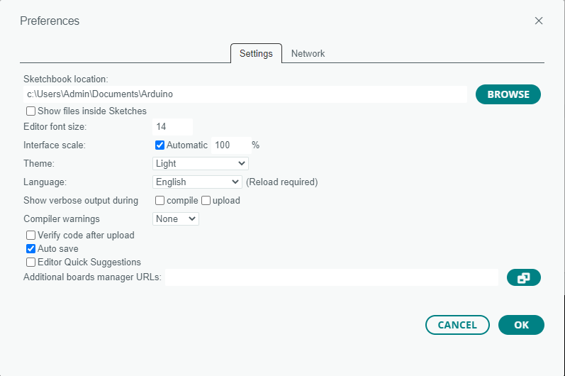
To switch to the English interface: Select File -> Preferences in the Arduino IDE interface. In the popup window, select English in the Language option, and then click OK.
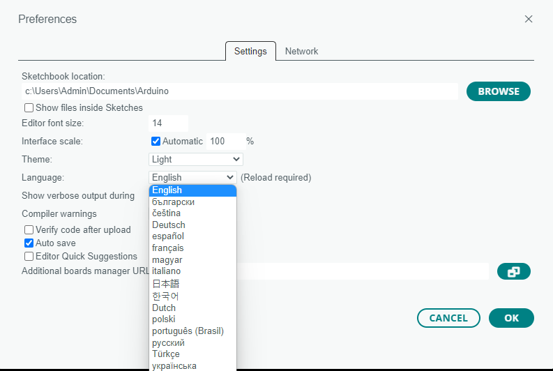
Select File -> Preferences to modify settings in the popup window, such as the project file path, editor font size, and color theme.
2.1.4 ESP32 Chip Package Installation
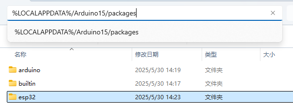
If any version of the ESP32 package other than 2.0.11 or 2.0.12 has been installed, delete it first. If no package has been installed, proceed directly to step 3.
Deletion method: Enter %LOCALAPPDATA%/Arduino15/packages in the address bar of the file manager, press Enter to open, and delete the esp32 folder.
Double-click the file esp32_package_2.0.11_arduinome.exe in the folder 01 Arduino Installation Package and Development Package under the same directory as this document, and wait for the installation to complete.

2.1.5 Library File Import (Must Read)
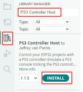
Subsequent programs require the official libraries PS3 Controller Host, MultiButton, and U8g2. Enter PS3 Controller Host, MultiButton, and U8g2 respectively in the library manager interface, and click Install as shown below.
Click the
 icon on the left sidebar of the Arduino IDE interface.
Enter PS3 Controller Host in the search bar of the library manager to search for the library file, and click INSTALL.
The appearance of the prompt shown below indicates a successful installation. The installation methods for the MultiButton and U8g2 libraries are identical to the steps above.

2.1.6 Arduino Program Upload
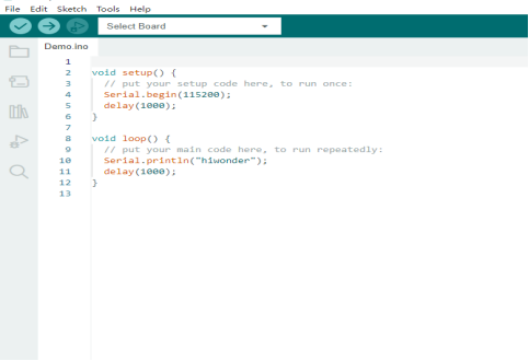
The demonstration uses a sample routine that prints hiwonder. In the folder 02 Program Source Code\01 Arduino Installation Package and Development Package\Demo under the same directory as this document, double-click to open the sample program Demo.ino.
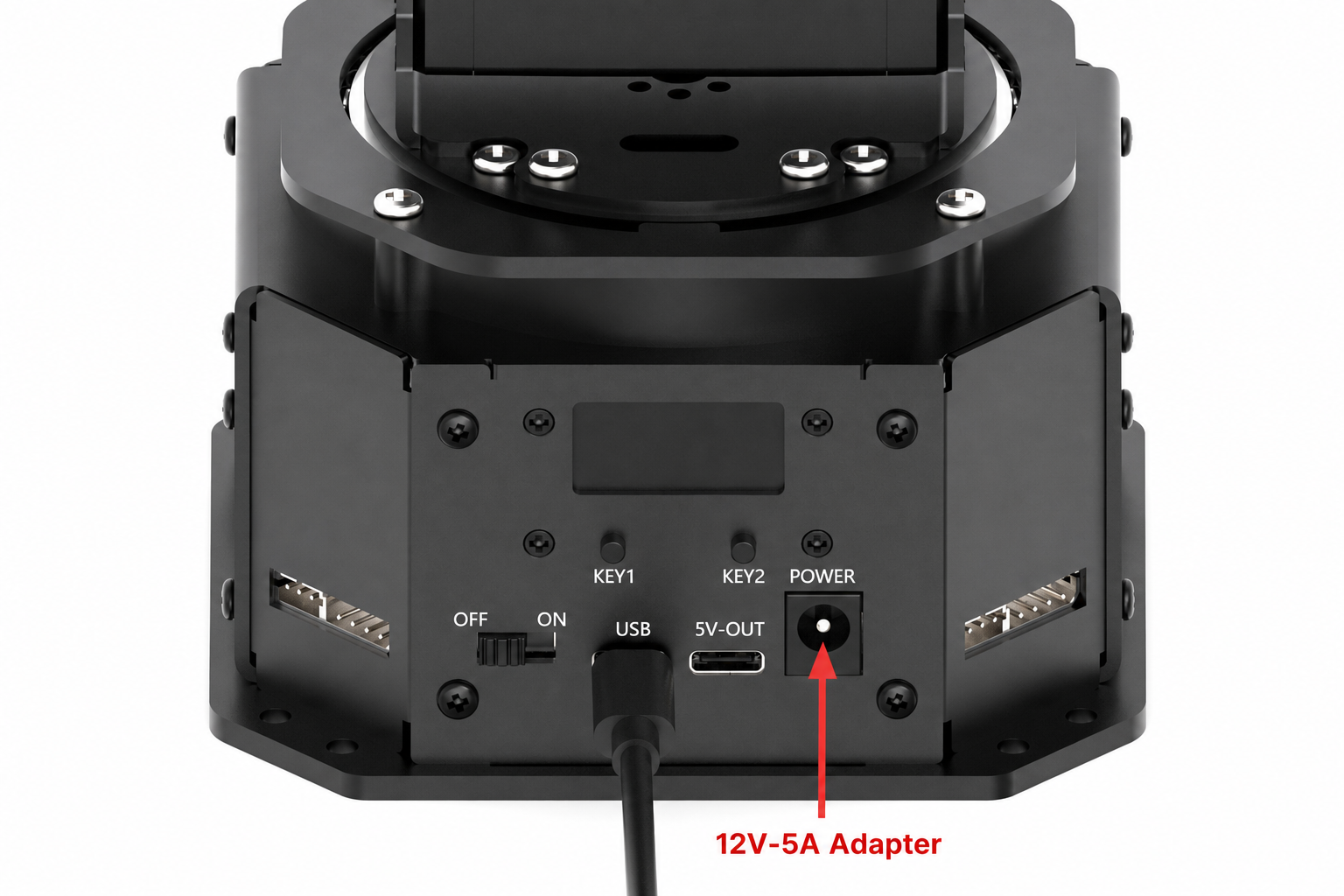
Connect the NexArm to the computer using a data cable.
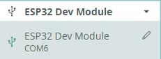
Select the corresponding development board for the Arduino in the Select Board option. The COM port is not unique. Check the COM port number in Device Manager on the computer. COM6 is used here as an example.
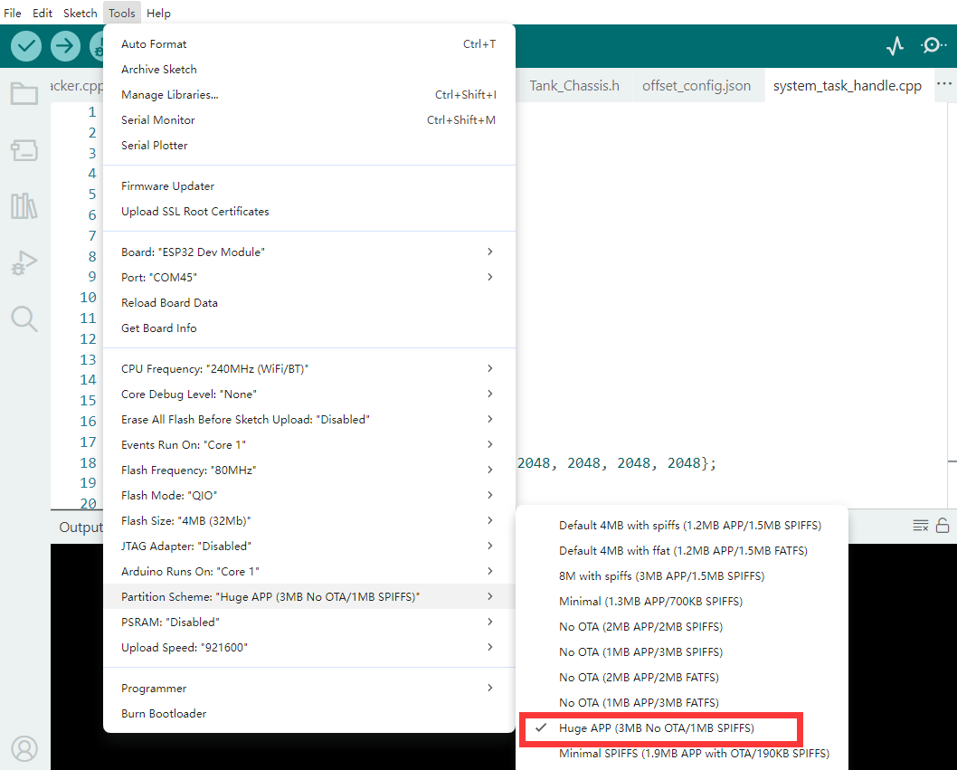
Click Tools on the menu bar, and configure the corresponding ESP32 development board settings according to the figure below.
Click the
 button to compile the program and verify if there are any syntax errors.

After successful compilation, click the
 button to upload the program to the ESP32 controller.

Once the upload is complete, click the
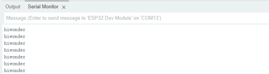
 icon to open the serial monitor. The message hiwonder is displayed in the serial monitor.
2.2 Single Bus Servo Control
2.2.1 Project Introduction
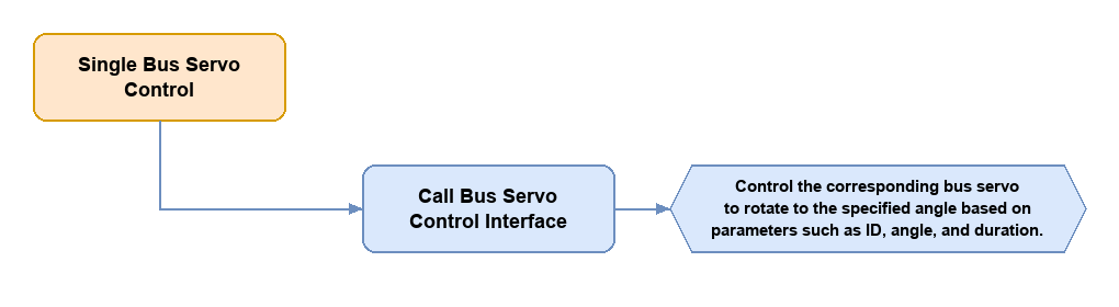
This section demonstrates how to control the rotation of a single bus servo using the encapsulated bus servo control functions, clarifying the control workflow of the bus servo and the invocation of related interfaces.
2.2.2 Program Flow
2.2.3 Module Description
NexArm mainly uses two magnetic encoder bus servos, HX-30HM and HX-65HM. The descriptions of these two servos are provided below.
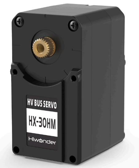
HX-30HM is a magnetic encoder bus servo developed by Hiwonder. It integrates the servo drive, motor, and bus signal. It communicates via a half-duplex UART asynchronous serial interface with a communication baud rate of up to 1,000,000 bps, achieving precise control through serial commands. The working voltage range of the servo is 9 to 12.6 V, with a rated voltage of 11.1 V. The unit features a total weight of 52 g and compact dimensions measuring 45.2 x 24.7 x 35 mm. It delivers a rated torque of 30 kg-cm at the nominal 11.1 V, while the rotation speed reaches 0.19 seconds per 60 degrees. Continuous 360-degree rotation is supported with a control resolution of 0.3 degrees, mapping the numerical range of 0 to 4095 directly to a full 0 to 360-degree span. Three operational modes are available, allowing smooth transitions between position control, closed-loop speed control, and open-loop speed control. An integrated magnetic encoder provides real-time angular feedback. Each module features three hardware interfaces, allowing a maximum of 253 units to be daisy-chained along the communication bus for synchronized multi-axis tasks. Safety configurations include non-volatile data storage upon power loss, stall protection, and overheat prevention. The system also delivers continuous telemetry feedback for core metrics, including temperature, voltage, and real-time position.

HX-65HM is a dual-shaft magnetic encoder smart serial bus servo developed by Hiwonder. It combines a servo driver, motor, and bus communication capabilities into a single housing, utilizing a half-duplex UART asynchronous serial interface at a baud rate of 1,000,000 bps to execute precision control via serial commands. The operating voltage range spans from 9 to 12.6 V with a nominal rating of 11.1 V. The unit features a weight of 143.5 g and compact dimensions measuring 45 x 25 x 70 mm. It delivers a peak torque of up to 65 kg-cm under an operating voltage of 12.6 V, while the actuation speed reaches 0.19 seconds per 60 degrees. Continuous 360-degree rotation capability is supported with a control resolution of 0.3 degrees, mapping the numerical range of 0 to 4095 directly to a full 0 to 360-degree span. Three operational modes are available, allowing smooth transitions between position control, closed-loop speed control, and open-loop speed control. An integrated magnetic encoder provides real-time angular data tracking. A maximum of 253 units can be daisy-chained along the communication bus for synchronized control. Safety configurations include non-volatile data storage upon power loss, thermal cutoffs, and power-down protection. The system also delivers continuous telemetry feedback for multiple operating parameters, including temperature, voltage, position, current, and velocity.
2.2.4 Program Upload
Locate the folder 02 Single Bus Servo Control\busservo_control inside the 02 Program Source Code directory under the same path as this document. Open the file busservo_control.ino. Refer to 2.1.6 Arduino Program Upload for the detailed upload steps.
2.2.5 Program Outcome
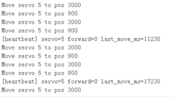
After the program is uploaded successfully, the servo with the corresponding ID first rotates to the central position angle of 2048. After a 2-second delay, the servo rotates cyclically between the angle positions of 1500 and 3000. Relevant prompt information is printed on the serial port.
2.2.6 Program Analysis
The event loop is created in
setup(), and thenregister_system_task()is called to complete the initialization. Inloop(),system_loop_handler()is continuously called. Therefore, the position switching of the single servo is continuously advanced in this main loop.
#include "Arduino.h"
#include "system_task_handle.h"

esp_event_loop_handle_t loop_handle;

void setup()
{
    esp_event_loop_args_t loop_args = {
        .queue_size = 10,
        .task_name = "sys_evt_loop",
        .task_priority = uxTaskPriorityGet(NULL),
        .task_stack_size = 4096,
        .task_core_id = tskNO_AFFINITY
    };

    esp_event_loop_create(&loop_args, &loop_handle);
    register_system_task(&loop_handle);
}

void loop()
{
    system_loop_handler();
}
Key parameters are defined at the beginning of the main program, including the servo ID, communication baud rate, acceleration, speed, and three target positions. Subsequent actions, whether returning to the central position or swinging left and right, are executed based on these constants.
namespace {
constexpr uint8_t  SERVO_ID         = 5;
constexpr uint32_t SERVO_BAUD       = 1000000;
constexpr uint8_t  ACC              = 80;
constexpr uint16_t SPEED            = 1200;
constexpr uint16_t POS_LOW          = 900;
constexpr uint16_t POS_HIGH         = 3000;
constexpr uint16_t POS_RESET        = 2048;
constexpr uint32_t MOVE_SETTLE_MS   = 1500;
constexpr uint32_t RESET_DELAY_MS   = 2000;

SerialServo_t servo;
bool target_high = true;
unsigned long last_action_ms = 0;
}
During initialization, the debugging serial port is opened, and then the bus servo serial port is initialized. The torque of the servo is enabled through
set_torque(true). Finally, the servo rotates to the central position2048. This ensures that the servo always starts from a unified initial position when subsequent experiments begin.
void register_system_task(esp_event_loop_handle_t* loop_handle)
{
    (void)loop_handle;
    Serial.begin(115200);
    delay(50);
    Serial.println("[SingleServo] start");

    servo.begin(Serial1, SERVO_BAUD, SERVO_TX_PIN, SERVO_RX_PIN);
    set_torque(true);

    servo.write_pos_ex(SERVO_ID, ACC, SPEED, POS_RESET);
    last_action_ms = millis();
}
The function
set_torque()is responsible for controlling the torque switch of the servo. A write register command is sent to the bus using the broadcast ID0xFEto write0or1to the torque switch register. This eliminates the need to write a separate interface for each servo.
static void set_torque(bool enable)
{
    uint8_t data[2];
    data[0] = ADDR_TORQUE_SWITCH;
    data[1] = enable ? 1 : 0;
    servo.tx_frame_write(BROADCAST_ID, CMD_WRITE, data, 2);
    delay(20);
}
The function
system_loop_handler()is the core of the action loop. The program first clears the serial port buffer. Then it determines whether to send a new position command based on the time interval. When the waiting time is reached, the servo switches back and forth between the two target positionsPOS_HIGHandPOS_LOW.
void system_loop_handler()
{
    while (servo.uart && servo.uart->available()) {
        servo.uart->read();
    }

    unsigned long now = millis();
    if (now - last_action_ms < (target_high ? RESET_DELAY_MS : MOVE_SETTLE_MS)) {
        delay(10);
        return;
    }

    uint16_t target = target_high ? POS_HIGH : POS_LOW;
    servo.write_pos_ex(SERVO_ID, ACC, SPEED, target);
    target_high = !target_high;
    last_action_ms = now;
}
The function
SerialServo_t::write_pos_ex()encapsulates the position control interface of a single servo. The function writes the acceleration, target position, and speed to the send buffer in sequence, and then callstx_frame_write()to send the complete data frame. The application layer only needs to pass the servo ID and target parameters, eliminating the need to construct the underlying protocol manually.
void SerialServo_t::write_pos_ex(uint8_t id, uint8_t acc, uint16_t speed, uint16_t pos)
{
    uint8_t data[8];
    data[0] = 0x29;
    data[1] = acc;
    data[2] = pos;
    data[3] = pos >> 8;
    data[4] = 0;
    data[5] = 0;
    data[6] = speed;
    data[7] = speed >> 8;
    tx_frame_write(id, 3, data, 8);
}
The function
tx_frame_write()is the underlying interface for bus protocol transmission. The function organizes the complete data packet in the format of frame header, ID, length, command, parameters, and checksum, and then sends it through the serial port. Since both single-servo control and multi-servo synchronous control ultimately rely on this layer, this function is key to understanding the format of the bus protocol.
void SerialServo_t::tx_frame_write(uint8_t id, uint8_t cmd, uint8_t* data, uint8_t len)
{
    uint8_t check = id + len + 2 + cmd;

    uart->write(0xFF);
    uart->write(0xFF);
    uart->write(id);
    uart->write(len + 2);
    uart->write(cmd);
    for (int i = 0; i < len; i++) {
        uart->write(data[i]);
        check += data[i];
    }
    uart->write(~check);
}
2.3 Bus Servo Status Reading
2.3.1 Project Introduction
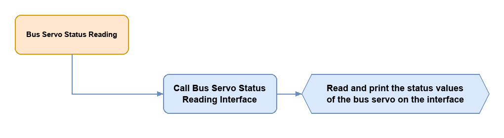
This section demonstrates how to read and print the status information of the bus servo using the encapsulated status reading functions, clarifying the status reading workflow of the bus servo and the invocation of related interfaces.
2.3.2 Program Flow
2.3.3 Module Description
NexArm mainly uses two magnetic encoder bus servos, HX-30HM and HX-65HM. The descriptions of these two servos are provided below.
HX-30HM is a magnetic encoder bus servo developed by Hiwonder. It integrates the servo drive, motor, and bus signal. It communicates via a half-duplex UART asynchronous serial interface with a communication baud rate of up to 1,000,000 bps, achieving precise control through serial commands. The working voltage range of the servo is 9 to 12.6 V, with a rated voltage of 11.1 V. The unit features a total weight of 52 g and compact dimensions measuring 45.2 x 24.7 x 35 mm. It delivers a rated torque of 30 kg-cm at the nominal 11.1 V, while the rotation speed reaches 0.19 seconds per 60 degrees. Continuous 360-degree rotation is supported with a control resolution of 0.3 degrees, mapping the numerical range of 0 to 4095 directly to a full 0 to 360-degree span. Three operational modes are available, allowing smooth transitions between position control, closed-loop speed control, and open-loop speed control. An integrated magnetic encoder provides real-time angular feedback. Each module features three hardware interfaces, allowing a maximum of 253 units to be daisy-chained along the communication bus for synchronized multi-axis tasks. Safety configurations include non-volatile data storage upon power loss, stall protection, and overheat prevention. The system also delivers continuous telemetry feedback for core metrics, including temperature, voltage, and real-time position.
HX-65HM is a dual-shaft magnetic encoder smart serial bus servo developed by Hiwonder. It combines a servo driver, motor, and bus communication capabilities into a single housing, utilizing a half-duplex UART asynchronous serial interface at a baud rate of 1,000,000 bps to execute precision control via serial commands. The operating voltage range spans from 9 to 12.6 V with a nominal rating of 11.1 V. The unit features a weight of 143.5 g and compact dimensions measuring 45 x 25 x 70 mm. It delivers a peak torque of up to 65 kg-cm under an operating voltage of 12.6 V, while the actuation speed reaches 0.19 seconds per 60 degrees. Continuous 360-degree rotation capability is supported with a control resolution of 0.3 degrees, mapping the numerical range of 0 to 4095 directly to a full 0 to 360-degree span. Three operational modes are available, allowing smooth transitions between position control, closed-loop speed control, and open-loop speed control. An integrated magnetic encoder provides real-time angular data tracking. A maximum of 253 units can be daisy-chained along the communication bus for synchronized control. Safety configurations include non-volatile data storage upon power loss, thermal cutoffs, and power-down protection. The system also delivers continuous telemetry feedback for multiple operating parameters, including temperature, voltage, position, current, and velocity.
2.3.4 Program Upload
Locate the folder Bus Servo Position Reading\busservo_read inside the 02 Program Source Code directory under the same path of this document. Open the file busservo_read.ino. Refer to 2.1.6 Arduino Program Upload for the detailed upload steps.
2.3.5 Program Outcome
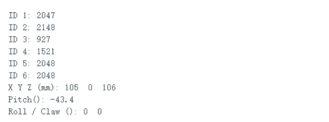
After the program starts, it scans the servos on the bus first. If any online servos are scanned, the serial port outputs the current angle and coordinate information of each servo ID in sequence.
2.3.6 Program Analysis
The event loop is created in
setup(), and thenregister_system_task()is called to complete the initialization of the serial port, bus servo, and status reading modules. Inloop(),system_loop_handler()is continuously called. Therefore, processes such as PING scans, register reading, and AT32 fallback printing are continuously advanced in this main loop.
#include "Arduino.h"
#include "system_task_handle.h"

esp_event_loop_handle_t loop_handle;

void setup()
{
    esp_event_loop_args_t loop_args = {
        .queue_size = 10,
        .task_name = "sys_evt_loop",
        .task_priority = uxTaskPriorityGet(NULL),
        .task_stack_size = 4096,
        .task_core_id = tskNO_AFFINITY
    };

    esp_event_loop_create(&loop_args, &loop_handle);
    register_system_task(&loop_handle);
}

void loop()
{
    system_loop_handler();
}
Parameters defined at the beginning of the main program include the servo communication baud rate, read interval, AT32 polling interval, status print interval, fixed ID list, and online servo cache. The program first attempts a PING scan for online servos. If no servos are found, the program switches to AT32 readback mode based on these flags.
static const uint32_t SERVO_BAUD = 1000000;
static const uint32_t READ_INTERVAL_MS = 2000;
static const uint32_t AT32_POLL_MS = 150;
static const uint32_t STATUS_PRINT_MS = 2000;

static const bool USE_PING_DISCOVER = true;
static const uint8_t FIXED_SERVO_IDS[] = { 4, 5, 6 };
static const bool AUTO_AT32_FALLBACK = true;

#define MAX_TRACKED_SERVOS 16
static uint8_t online_ids[MAX_TRACKED_SERVOS];
static uint8_t online_count = 0;
static bool g_at32_poll_mode = false;
The function
register_system_task()initializes the serial port, bus servo, and torque. Then it determines whether to scan the bus or directly load the fixed ID list based onUSE_PING_DISCOVER. If no servos respond to PING, the program automatically enablesCommProtocolto request the onboard AT32 to return the current pose and joint pulse values.
void register_system_task(esp_event_loop_handle_t *event_loop)
{
    (void)event_loop;

    Serial.begin(115200);
    delay(200);

    servo.begin(Serial1, SERVO_BAUD, SERVO_TX_PIN, SERVO_RX_PIN);
    delay(50);

    flush_servo_rx();
    set_torque(true);
    delay(AFTER_TORQUE_MS);
    flush_servo_rx();

    uint16_t at32_like = 0;
    if (USE_PING_DISCOVER)
        run_ping_discovery(&at32_like);
    else
        load_fixed_id_list();

    g_at32_poll_mode = (online_count == 0 && AUTO_AT32_FALLBACK);
    if (g_at32_poll_mode) {
        g_bus_proto.begin();
        g_bus_proto.register_success_callback(at32_packet_callback);
        request_at32_poll_one();
    }

    last_read_ms = millis();
}
The function
run_ping_discovery()is used to scan servos within the specified ID range. The function sendsCMD_PINGto each ID. If a servo responds correctly, its ID is stored inonline_ids[]. Consequently, the subsequent reading phase only needs to poll the servos confirmed to be online.
static void run_ping_discovery(uint16_t *out_at32_like_count)
{
    online_count = 0;
    memset(online_ids, 0, sizeof(online_ids));
    *out_at32_like_count = 0;

    for (uint8_t id = PING_SCAN_ID_MIN; id <= PING_SCAN_ID_MAX; id++) {
        flush_servo_rx();
        delay(PING_GAP_MS);

        bool ok = servo.ping(id);
        if (ok) {
            if (online_count < MAX_TRACKED_SERVOS)
                online_ids[online_count++] = id;
        } else {
            if (servo.last_read_err == -4 && servo.last_read_rx_id == AT32_RESP_ID &&
                servo.last_read_bytes >= 6)
                (*out_at32_like_count)++;
        }
        delay(PING_GAP_MS);
    }
}
Once the program enters AT32 fallback mode,
at32_packet_callback()specifically parses the response packets ofCMD_GET_CUR_COORDSandCMD_GET_REAL_JOINT_ANGLES. The former extracts the end values ofx,y,z,pitch,roll, andclawwhile the latter extracts the 6-way joint pulse values. This enables retrieving the state of the entire robot arm through the onboard AT32 even if the bus servos do not respond directly.
static void at32_packet_callback(PacketTypeDef *rx_packet)
{
    if (rx_packet->elements.id != AT32_RESP_ID)
        return;

    if (rx_packet->elements.cmd == CMD_GET_CUR_COORDS &&
        rx_packet->elements.length >= 26) {
        g_snap_x = (int16_t)((rx_packet->elements.args[1] << 8) | rx_packet->elements.args[0]);
        g_snap_y = (int16_t)((rx_packet->elements.args[3] << 8) | rx_packet->elements.args[2]);
        g_snap_z = (int16_t)((rx_packet->elements.args[5] << 8) | rx_packet->elements.args[4]);
        g_snap_pitch_x10 = (int16_t)((rx_packet->elements.args[7] << 8) | rx_packet->elements.args[6]);
        g_snap_roll = (int16_t)((rx_packet->elements.args[9] << 8) | rx_packet->elements.args[8]);
        g_snap_claw = (int16_t)((rx_packet->elements.args[11] << 8) | rx_packet->elements.args[10]);
        return;
    }

    if (rx_packet->elements.cmd == CMD_GET_REAL_JOINT_ANGLES &&
        rx_packet->elements.length >= 26) {
        for (int i = 0; i < 6; i++) {
            int16_t pulse = (int16_t)((rx_packet->elements.args[i * 4 + 1] << 8) |
                                      rx_packet->elements.args[i * 4]);
            g_snap_pulse[i] = pulse;
        }
    }
}
The functions
ping(),read_reg(), andread_servo_status()constitute the status reading chain of the bus servo. The functionping()is used to confirm whether a specific ID is online. The functionread_reg()is responsible for reading the specified number of bytes based on the register address. The functionread_servo_status()further parses the position, speed, load, voltage, temperature, current, center offset, and working mode.
bool SerialServo_t::ping(uint8_t id)
{
    uint8_t req[] = { FRAME_HEADER_1, FRAME_HEADER_2, id, 2, CMD_PING };
    uint8_t ck = data_check(req, 5);
    uart->write(req, 5);
    uart->write(&ck, 1);
    ...
}

int SerialServo_t::read_reg(uint8_t id, uint8_t start_addr, uint8_t count, uint8_t *out)
{
    uint8_t req[2] = { start_addr, count };
    tx_frame_write(id, CMD_READ, req, 2);
    ...
}

bool SerialServo_t::read_servo_status(uint8_t id, ServoStatus_t *status)
{
    uint8_t raw[16];
    int n = read_reg(id, REG_PRESENT_POSITION_L, 15, raw);
    if (n != 15)
        return false;
    ...
}
The function
print_servo_by_hx_protocol()prints the read servo status results as readable messages. The function first callsread_servo_status()to read the main status block, and then reads additional registers such as the target position and target speed. Finally, it organizes the angle, speed, load, voltage, temperature, and working mode, and outputs them to the serial port.
static void print_servo_by_hx_protocol(uint8_t id)
{
    ServoStatus_t st;
    if (!servo.read_servo_status(id, &st)) {
        Serial.printf("[ID=%u] CMD_READ failed err=%d rx=%u\n", (unsigned)id,
                      servo.last_read_err, (unsigned)servo.last_read_bytes);
        return;
    }

    float deg = (POS_TICKS_PER_TURN > 0.1f)
                    ? ((float)st.position * 360.0f / POS_TICKS_PER_TURN)
                    : 0.f;

    Serial.printf("========== HX-30HM ID=%u ==========\n", (unsigned)id);
    Serial.printf("  [Reg56-57] Current Position: %d  (≈%.2f°)\n", (int)st.position, deg);
    Serial.printf("  [Reg58-59] Velocity: %d  [Reg60-61]Load: %d\n", (int)st.speed, (int)st.load);
    Serial.printf("  [Reg62] Voltage: %.1f V  [Reg63] Temperature: %u ℃\n",
                  st.voltage * 0.1f, (unsigned)st.temperature);
}
Two different paths are followed in
system_loop_handler()based on the current mode. Ifg_at32_poll_modeis enabled, the program continuously feeds serial port bytes into the protocol parser and requests the pose and joint angles at a fixed interval. If online servos are scanned, it reads and prints the status of each online servo in sequence according to theREAD_INTERVAL_MScycle.
void system_loop_handler(void)
{
    if (g_at32_poll_mode) {
        if (servo.uart) {
            while (servo.uart->available()) {
                uint8_t c = servo.uart->read();
                g_bus_proto.parsing(&c, 1);
            }
        }
        uint32_t now = millis();
        if ((uint32_t)(now - g_last_at32_poll_ms) >= AT32_POLL_MS) {
            g_last_at32_poll_ms = now;
            request_at32_poll_one();
        }
        if ((uint32_t)(now - g_last_status_print_ms) >= STATUS_PRINT_MS) {
            g_last_status_print_ms = now;
            emit_at32_status_block();
        }
        delay(1);
        return;
    }

    if (millis() - last_read_ms < READ_INTERVAL_MS) {
        delay(1);
        return;
    }
    last_read_ms = millis();

    for (uint8_t i = 0; i < online_count; i++)
        print_servo_by_hx_protocol(online_ids[i]);
}
2.4 Synchronous Control of Multiple Bus Servos
2.4.1 Project Introduction
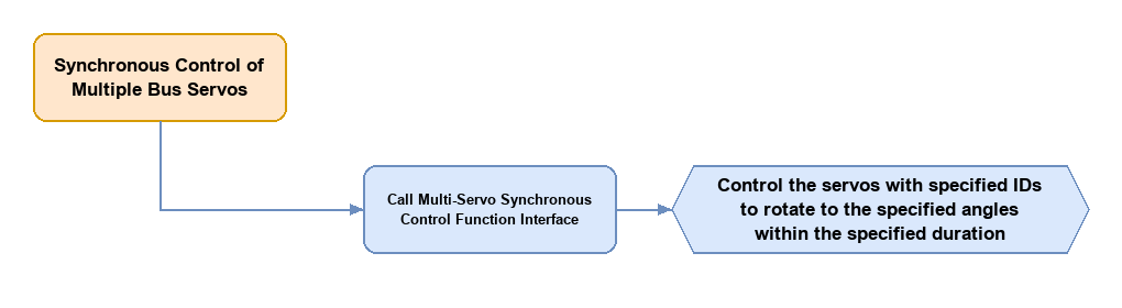
This section demonstrates how to control multiple bus servos to rotate to specified angles simultaneously using the encapsulated synchronous control functions, clarifying the synchronous control workflow of multiple bus servos and the invocation of related interfaces.
2.4.2 Program Flow
2.4.3 Module Description
NexArm mainly uses two magnetic encoder bus servos, HX-30HM and HX-65HM. The descriptions of these two servos are provided below.
HX-30HM is a magnetic encoder bus servo developed by Hiwonder. It integrates the servo drive, motor, and bus signal. It communicates via a half-duplex UART asynchronous serial interface with a communication baud rate of up to 1,000,000 bps, achieving precise control through serial commands. The working voltage range of the servo is 9 to 12.6 V, with a rated voltage of 11.1 V. The unit features a total weight of 52 g and compact dimensions measuring 45.2 x 24.7 x 35 mm. It delivers a rated torque of 30 kg-cm at the nominal 11.1 V, while the rotation speed reaches 0.19 seconds per 60 degrees. Continuous 360-degree rotation is supported with a control resolution of 0.3 degrees, mapping the numerical range of 0 to 4095 directly to a full 0 to 360-degree span. Three operational modes are available, allowing smooth transitions between position control, closed-loop speed control, and open-loop speed control. An integrated magnetic encoder provides real-time angular feedback. Each module features three hardware interfaces, allowing a maximum of 253 units to be daisy-chained along the communication bus for synchronized multi-axis tasks. Safety configurations include non-volatile data storage upon power loss, stall protection, and overheat prevention. The system also delivers continuous telemetry feedback for core metrics, including temperature, voltage, and real-time position.
HX-65HM is a dual-shaft magnetic encoder smart serial bus servo developed by Hiwonder. It combines a servo driver, motor, and bus communication capabilities into a single housing, utilizing a half-duplex UART asynchronous serial interface at a baud rate of 1,000,000 bps to execute precision control via serial commands. The operating voltage range spans from 9 to 12.6 V with a nominal rating of 11.1 V. The unit features a weight of 143.5 g and compact dimensions measuring 45 x 25 x 70 mm. It delivers a peak torque of up to 65 kg-cm under an operating voltage of 12.6 V, while the actuation speed reaches 0.19 seconds per 60 degrees. Continuous 360-degree rotation capability is supported with a control resolution of 0.3 degrees, mapping the numerical range of 0 to 4095 directly to a full 0 to 360-degree span. Three operational modes are available, allowing smooth transitions between position control, closed-loop speed control, and open-loop speed control. An integrated magnetic encoder provides real-time angular data tracking. A maximum of 253 units can be daisy-chained along the communication bus for synchronized control. Safety configurations include non-volatile data storage upon power loss, thermal cutoffs, and power-down protection. The system also delivers continuous telemetry feedback for multiple operating parameters, including temperature, voltage, position, current, and velocity.
2.4.4 Program Upload
Locate the folder 04 Synchronous Control of Multiple Bus Servos\multi_servo_control inside the 02 Program Source Code directory under the same path as this document. Open the file multi_servo_control.ino. Refer to 2.1.6 Arduino Program Upload for the detailed upload steps.
2.4.5 Program Outcome
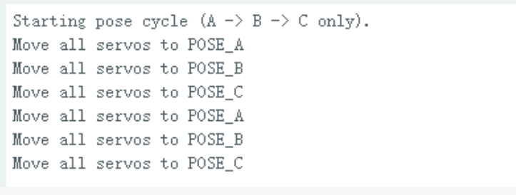
After the program is executed, the robot arm first returns to the agreed default extended position. After a short pause, the program enters a loop. Multiple servos operate together at the set speed at the same time, switching repeatedly among three postures. Sufficient time is allowed between each step for the servos to reach their positions. Opening the serial monitor displays startup prompts, the ready status of the default position, and cycle start descriptions.
2.4.6 Program Analysis
The event loop is created in
setup()andregister_system_task()is called to complete the initialization. Inloop(),system_loop_handler()is executed continuously. Therefore, the synchronous switching actions of multiple servos are also scheduled and completed continuously by the main loop.
#include "Arduino.h"
#include "system_task_handle.h"

esp_event_loop_handle_t loop_handle;

void setup()
{
    esp_event_loop_args_t loop_args = {
        .queue_size = 10,
        .task_name = "sys_evt_loop",
        .task_priority = uxTaskPriorityGet(NULL),
        .task_stack_size = 4096,
        .task_core_id = tskNO_AFFINITY
    };

    esp_event_loop_create(&loop_args, &loop_handle);
    register_system_task(&loop_handle);
}

void loop()
{
    system_loop_handler();
}
Key parameters for the synchronous control experiment are defined at the beginning of the main program, including two servo IDs, synchronous speed, action wait time, and three sets of target postures. Posture data is saved in an array. Changing actions afterward only requires modifying the array index.
namespace {
constexpr uint8_t  SERVO_IDS[] = {5, 6};
constexpr uint8_t  SERVO_NUM   = sizeof(SERVO_IDS) / sizeof(SERVO_IDS[0]);
constexpr uint32_t SERVO_BAUD  = 1000000;
constexpr uint16_t SPEED       = 1200;
constexpr uint32_t MOVE_SETTLE_MS       = 2200;
constexpr uint32_t RESET_DELAY_MS       = 2000;
constexpr uint32_t ARM_RESET_DURATION_MS = 2000;

const int16_t POSE_A[SERVO_NUM] = {2048, 2048};
const int16_t POSE_B[SERVO_NUM] = {760, 1000};
const int16_t POSE_C[SERVO_NUM] = {3300, 2800};
const int16_t* POSES[] = {POSE_A, POSE_B, POSE_C};

SerialServo_t servo;
Robot_Arm arm;
uint8_t current_pose_idx = 0;
bool reset_done = false;
unsigned long last_reset_done_ms = 0;
}
Three helper functions are defined first in the file. The function
move_arm_to_default_pose()is used to return the entire machine to the default position. The functionset_torque()is responsible for enabling the servo torque. The functionmove_to_pose()sends a set of target positions to multiple servos simultaneously via a synchronous write command.
static void move_arm_to_default_pose()
{
    arm.reset_all(ARM_RESET_DURATION_MS);
}

static void set_torque(bool enable)
{
    uint8_t data[2];
    data[0] = ADDR_TORQUE_SWITCH;
    data[1] = enable ? 1 : 0;
    servo.tx_frame_write(BROADCAST_ID, CMD_WRITE, data, 2);
    delay(20);
}

static void move_to_pose(const int16_t* pose)
{
    servo.sync_write_pos_speed(SERVO_IDS, pose, SPEED, SERVO_NUM);
}
During initialization, the debugging serial port, bus servo serial port, and robot arm object are initialized. Then, the servo torque is enabled. Finally,
move_arm_to_default_pose()is called to return the robot arm to the default position. This ensures that the subsequent synchronous control starts from a unified posture.
void register_system_task(esp_event_loop_handle_t* loop_handle)
{
    (void)loop_handle;
    Serial.begin(115200);
    delay(50);
    Serial.println("[MultiServo] start");

    servo.begin(Serial1, SERVO_BAUD, SERVO_TX_PIN, SERVO_RX_PIN);
    arm.begin();

    set_torque(true);
    move_arm_to_default_pose();

    last_reset_done_ms = millis();
    reset_done = true;
}
The function
system_loop_handler()is the main state scheduling function. The program first waits for the default position action to complete, and then switches to the three posturesPOSE_A,POSE_B, andPOSE_Cin sequence. After sending the synchronous write command each time, the program waits for a duration to ensure that the servos have sufficient operating time to complete the action.
void system_loop_handler()
{
    while (servo.uart && servo.uart->available()) {
        servo.uart->read();
    }

    unsigned long now = millis();
    if (!reset_done) {
        delay(10);
        return;
    }

    if (now - last_reset_done_ms < RESET_DELAY_MS && current_pose_idx == 0) {
        delay(10);
        return;
    }

    static unsigned long last_move_ms = 0;
    if (now - last_move_ms < MOVE_SETTLE_MS) {
        delay(10);
        return;
    }

    move_to_pose(POSES[current_pose_idx]);
    current_pose_idx = (current_pose_idx + 1) % (sizeof(POSES) / sizeof(POSES[0]));
    last_move_ms = now;
}
The function
Robot_Arm::reset_all()is used to return the entire robot arm to the default position. The function internally callsmove()to send a set of default end poses. Therefore, before starting the multi-servo synchronization, this experiment uses the kinematics interface to adjust the robot arm to a posture that is easy to observe.
bool Robot_Arm::reset_all(int16_t duration_ms)
{
    return move(200.0f, 0.0f, 200.0f, 0.0f, 0.0f, 0.0f, duration_ms);
}
The function
SerialServo_t::sync_write_pos_speed()is the core interface of this section. The function packages the IDs, target positions, and speeds of multiple servos into a single broadcast synchronous write frame, which is sent to the bus to start the actions of multiple servos simultaneously.
void SerialServo_t::sync_write_pos_speed(const uint8_t* id, const int16_t* pos, uint16_t speed, uint8_t num)
{
    uint8_t data[64];
    uint8_t idx = 0;
    data[idx++] = 0x2A;
    data[idx++] = 0x06;
    for (uint8_t i = 0; i < num; i++) {
        data[idx++] = id[i];
        data[idx++] = pos[i];
        data[idx++] = pos[i] >> 8;
        data[idx++] = 0;
        data[idx++] = 0;
        data[idx++] = speed;
        data[idx++] = speed >> 8;
    }
    tx_frame_write(0xFE, 131, data, idx);
}
The underlying
tx_frame_write()is still responsible for protocol packaging and serial transmission. Compared to single-servo control, the main difference is that the ID uses the broadcast address0xFEand the instruction is a synchronous write command. Therefore, multiple servos on the bus parse and execute this data frame at the same time.
void SerialServo_t::tx_frame_write(uint8_t id, uint8_t cmd, uint8_t* data, uint8_t len)
{
    uint8_t check = id + len + 2 + cmd;

    uart->write(0xFF);
    uart->write(0xFF);
    uart->write(id);
    uart->write(len + 2);
    uart->write(cmd);
    for (int i = 0; i < len; i++) {
        uart->write(data[i]);
        check += data[i];
    }
    uart->write(~check);
}
2.5 Button Scanning and Buzzer
2.5.1 Project Introduction
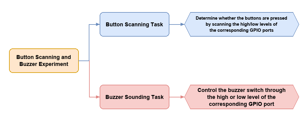
This experiment triggers different buzzer prompts via two buttons on the NexArm controller, teaching basic methods for button scanning, state determination, and buzzer driving. The program continuously updates the button and buzzer states in a loop. When a click is detected on either the BOOT button or the USER button, prompts with different frequencies and repetition counts are emitted, and the current event is output via the serial port.
2.5.2 Program Flow
2.5.3 Module Description
Buzzer: The model of the buzzer mounted on NexArm is BUZZ-8530, which is a common active electromagnetic buzzer. The operating voltage is typically 3 to 5 V, making it compatible with 3.3 V and 5 V microcontroller systems. The buzzer integrates an internal oscillation drive circuit. It automatically emits sound at a fixed frequency when the rated DC voltage is applied to the positive and negative poles, requiring no external drive signals, which makes it extremely simple to use. The operating frequency is generally around 2300 Hz, the no-load current is within approximately 30 mA, and the sound pressure level can reach above 85 dB. This meets the requirements of most application scenarios, such as prompt tones and warning alarms.
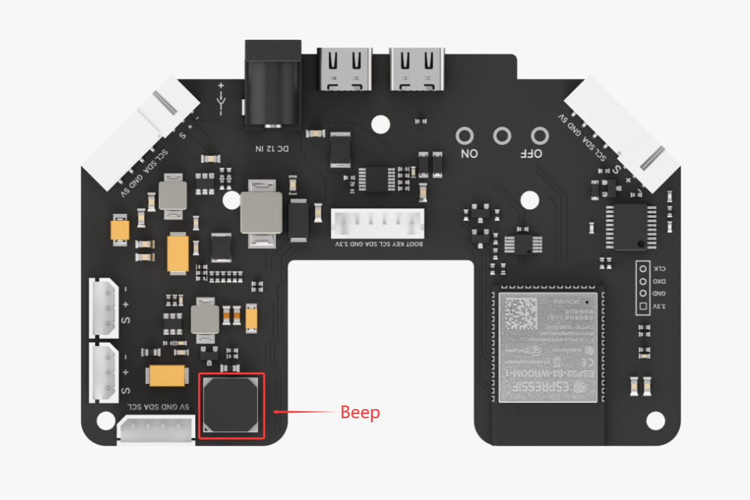
Buttons: NexArm is equipped with two tactile buttons directly connected to the GPIO ports of the ESP32 microcontroller. Both buttons use common self-resetting tactile SMD buttons. The corresponding signal is triggered when pressed, and the button automatically springs back when released. The buttons are characterized by a simple structure, long lifespan, and sensitive response, which matches the human-robot interaction design requirements of embedded controllers. The overall button design follows the principle of minimization, simplifying the hardware structure as much as possible while ensuring necessary debugging and control functions.
2.5.4 Program Upload
Locate the folder 05 Button Scanning and Buzzer Control\KeyScan_Beep inside the 02 Program Source Code directory under the same path of this document. Open the file KeyScan_Beep.ino. Refer to 2.1.6 Arduino Program Upload for the detailed upload steps.
2.5.5 Program Outcome
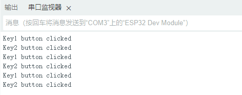
After the program is uploaded, the serial port first outputs the experiment startup prompt. When clicking the KEY1 button, the buzzer emits a single short prompt tone. When clicking the KEY2 button, the buzzer emits a double short prompt tone. The serial port synchronously prints the corresponding button trigger information.
2.5.6 Program Analysis
The event loop is created in
setup()first, and thenregister_system_task()is called to complete the initialization. Inloop(),system_loop_handler()is executed continuously. Therefore, both button scanning and buzzer status refreshing rely on the continuous execution of this main loop.
#include "Arduino.h"
#include "system_task_handle.h"

esp_event_loop_handle_t loop_handle;

void setup()
{
    esp_event_loop_args_t loop_args = {
        .queue_size = 10,
        .task_name = "sys_evt_loop",
        .task_priority = uxTaskPriorityGet(NULL),
        .task_stack_size = 4096,
        .task_core_id = tskNO_AFFINITY
    };

    esp_event_loop_create(&loop_args, &loop_handle);
    register_system_task(&loop_handle);
}

void loop()
{
    system_loop_handler();
}
The button object, buzzer object, and related parameters are defined in the anonymous namespace at the beginning of the main program. Subsequent triggers for any prompt tone are executed around these objects and constants.
namespace {
Button_t g_button;
Buzzer_t g_buzzer;

constexpr uint16_t BOOT_BEEP_FREQ = 2000;
constexpr uint16_t USER_BEEP_FREQ = 3000;
constexpr uint32_t LOOP_DELAY_MS = 10;
}
The function
register_system_task()is responsible for the preparation work when the experiment starts. The program first initializes the serial port and the buzzer, plays a startup prompt tone, and outputs the current experiment description via the serial port.
void register_system_task(esp_event_loop_handle_t *event_loop)
{
    (void)event_loop;

    Serial.begin(115200);
    delay(100);

    g_buzzer.begin();
    g_buzzer.set(60, 0, 1, BOOT_BEEP_FREQ);

    Serial.println("Simple button + buzzer demo started.");
    Serial.println("BOOT button -> single short beep");
    Serial.println("USER button -> double short beep");
}
The function
system_loop_handler()is the core loop of the experiment. The program first updates the button state, and then refreshes the buzzer state machine. If a button click is detected, it callsset()to write the sounding duration, interval, and repetition count for the buzzer.
void system_loop_handler(void)
{
    g_button.update();
    g_buzzer.update();

    if (g_button.is_clicked(0)) {
        g_buzzer.set(100, 80, 1, BOOT_BEEP_FREQ);
        Serial.println("BOOT button clicked");
    }

    if (g_button.is_clicked(1)) {
        g_buzzer.set(80, 80, 2, USER_BEEP_FREQ);
        Serial.println("USER button clicked");
    }

    delay(LOOP_DELAY_MS);
}
The class
Button_tprovides a unified encapsulation for the two buttons. The functionupdate()refreshes the button state in each loop, andis_clicked()returns whether a click event occurs on the BOOT button or the USER button based on the passed ID.
void Button_t::update()
{
    Boot_Button.update();
    User_Button.update();
}

bool Button_t::is_clicked(uint8_t id)
{
    return id == 0 ? Boot_Button.isClick() : User_Button.isClick();
}
The function
Buzzer_t::begin()completes the buzzer hardware initialization, andset()is used to write the parameters of the sounding task. After callingset(), the state machine executes the sounding task step by step in subsequent loops based on the set parameters.
void Buzzer_t::begin()
{
    allow_change = true;

    this->ticks_on = 0;
    this->ticks_off = 0;
    this->times = 0;
    this->freq = 2000;

    stage = BUZZER_STAGE_START_NEW_CYCLE;
    pinMode(BUZZER_PIN, OUTPUT);
    digitalWrite(BUZZER_PIN, LOW);
    ledcAttachPin(BUZZER_PIN, 0);
}

bool Buzzer_t::set(uint32_t on_time , uint32_t off_time , uint16_t times, uint16_t freq)
{
  if(allow_change) {
    this->ticks_on = on_time;
    this->ticks_off = off_time;
    this->times = times;
    this->freq = freq;
    this->stage = BUZZER_STAGE_START_NEW_CYCLE;
    return true;
  }
  return false;
}
The function
Buzzer_t::update()uses an internal state machine to control the sounding process of the buzzer.BUZZER_STAGE_START_NEW_CYCLEis used to start a new ring,BUZZER_STAGE_WATTING_OFFcontrols the sounding duration, andBUZZER_STAGE_WATTING_PERIOD_ENDcontrols the interval between two soundings. Therefore, the entire prompt tone process does not require blocking delays.
void Buzzer_t::update()
{
    switch(stage) {
    case BUZZER_STAGE_START_NEW_CYCLE:
        if(ticks_on > 0) {
            tone(BUZZER_PIN, freq);
            if(ticks_off > 0) {
                ticks_count = 0;
                stage = BUZZER_STAGE_WATTING_OFF;
            } else {
                stage = BUZZER_STAGE_IDLE;
            }
        } else {
            noTone(BUZZER_PIN);
            stage = BUZZER_STAGE_IDLE;
        }
        break;
    case BUZZER_STAGE_WATTING_OFF:
        ticks_count += update_period;
        if(ticks_count >= ticks_on) {
            noTone(BUZZER_PIN);
            stage = BUZZER_STAGE_WATTING_PERIOD_END;
        }
        break;
    case BUZZER_STAGE_WATTING_PERIOD_END:
        ticks_count += update_period;
        if(ticks_count >= (ticks_off + ticks_on)) {
            ticks_count -= (ticks_off + ticks_on);
            if(times == 1) {
                noTone(BUZZER_PIN);
                stage = BUZZER_STAGE_IDLE;
            } else {
                tone(BUZZER_PIN, freq);
                times = times == 0 ? 0 : times - 1;
                stage = BUZZER_STAGE_WATTING_OFF;
            }
        }
        break;
    case BUZZER_STAGE_IDLE:
        break;
    }
}
2.6 OLED Display
2.6.1 Project Introduction
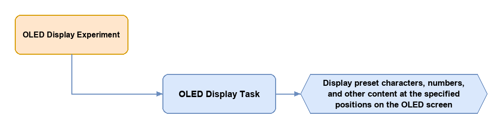
This experiment uses the onboard OLED display to show real-time text information, teaching the methods of I2C device initialization, text cache updating, and periodic display refreshing. After starting, the program first detects whether the OLED is connected successfully. It then periodically updates the counter value and system uptime, showing this content on the screen.
2.6.2 Program Flow
2.6.3 Module Description
The OLED display uses the SSD1306 control chip and has a resolution of 128 × 64 pixels, which is a monochrome OLED screen. The screen communicates with the main controller through the I2C bus, and the I2C device address of the OLED is 0x3C. In terms of hardware connection, the SDA data line of the OLED is connected to the main control GPIO26, the SCL clock line is connected to the main control GPIO27, and the I2C communication clock is set to 400 kHz. The OLED does not have an independently configured reset pin, and the reset pin parameter is set as unused. The screen display direction is set to R2, which rotates the display 180 degrees relative to the default direction.
2.6.4 Program Upload
Locate the folder 06 OLED Display\Oled_display inside the 02 Program Source Code directory under the same path as this document. Open the file Oled_display.ino. Refer to 2.1.6 Arduino Program Upload for the detailed upload steps.
2.6.5 Program Outcome
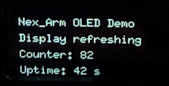
After the program runs, the OLED screen displays the experiment title, current status, refresh counter value, and system uptime. The serial port synchronously outputs the refresh counts, facilitating the observation of whether the program runs normally according to the set cycle.
2.6.6 Program Analysis
The OLED object, initialization flags, refresh timestamp, and refresh counter are defined at the beginning of the main program. These variables collectively determine the refresh interval of the screen and the count of completed refreshes.
namespace {
OLED_t g_oled;
bool g_oled_ready = false;
unsigned long g_last_refresh_ms = 0;
unsigned long g_counter = 0;

constexpr unsigned long REFRESH_INTERVAL_MS = 500;
}
The function
register_system_task()first callsg_oled.begin()to check whether the OLED is connected successfully. After a successful initialization, the program writes the four lines of content to be displayed into the cache, and immediately callsshow_custom()to complete the initial display.
void register_system_task(esp_event_loop_handle_t *event_loop)
{
    (void)event_loop;

    Serial.begin(115200);
    delay(100);

    g_oled_ready = g_oled.begin();
    if (g_oled_ready) {
        Serial.println("OLED demo started.");
        g_oled.set_custom_text(0, "Nex_Arm OLED Demo");
        g_oled.set_custom_text(1, "Display ready");
        g_oled.set_custom_text(2, "Counter: 0");
        g_oled.set_custom_text(3, "Uptime: 0 s");
        g_oled.show_custom();
    } else {
        Serial.println("OLED init failed.");
    }
}
The function
system_loop_handler()first determines whether the OLED has been initialized successfully. If not, it returns directly. Otherwise, it updates the counter value and uptime everyREFRESH_INTERVAL_MSmilliseconds, and writes the latest content back to the screen.
void system_loop_handler(void)
{
    if (!g_oled_ready) {
        delay(100);
        return;
    }

    unsigned long now = millis();

    if (now - g_last_refresh_ms >= REFRESH_INTERVAL_MS) {
        g_last_refresh_ms = now;
        g_counter++;

        g_oled.set_custom_text(0, "Nex_Arm OLED Demo");
        g_oled.set_custom_text(1, "Display refreshing");
        g_oled.set_custom_text(2, "Counter: " + String(g_counter));
        g_oled.set_custom_text(3, "Uptime: " + String(now / 1000) + " s");
        g_oled.show_custom();

        Serial.print("OLED refresh #");
        Serial.println(g_counter);
    }

    delay(10);
}
The function
OLED_t::begin()is responsible for the underlying I2C initialization. The program first sets the SDA and SCL pins and the bus clock, and then attempts to send a communication signal to the OLED address. Only after a successful communication does it callu8g2.begin()to start the display library.
bool OLED_t::begin()
{
    Wire.setPins(I2C_SDA_PIN, I2C_SCL_PIN);
    Wire.begin();
    Wire.setClock(400000);
    Wire.beginTransmission(OLED_I2C_ADDR);
    if(!Wire.endTransmission()) {
        u8g2.begin();
        return true;
    }
    return false;
}
The function
set_custom_text()only writes strings to the four-line cache. The actual screen refreshing is completed inshow_custom(). The functionshow_custom()sets the cursor position line by line and displays each line of text in the cache in sequence.
void OLED_t::set_custom_text(uint8_t line, String text)
{
    if(line < 4) {
        custom_lines[line] = text;
    }
}

void OLED_t::show_custom()
{
    u8g2.firstPage();
    do {
        u8g2.setFont(u8g2_font_6x10_tr);
        for(int i = 0; i < 4; i++) {
            u8g2.setCursor(0, 15 + i * 15);
            u8g2.print(custom_lines[i]);
        }
    } while (u8g2.nextPage());
}
2.7 FLASH File System Operation
2.7.1 Project Introduction
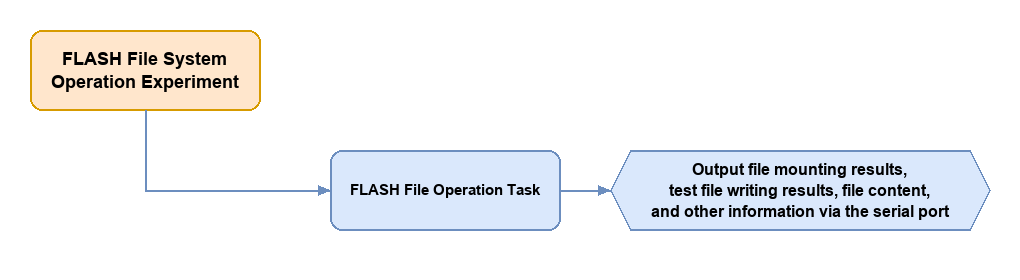
This experiment uses the LittleFS file system of the ESP32 to complete file creation, writing, reading, and directory traversal operations, introducing the basic usage of the Flash file system. After startup, the program first mounts LittleFS, creates a test file, writes sample content and reads it out immediately, and finally lists the file information in the root directory.
2.7.2 Program Flow
2.7.3 Module Description
The Flash file system module of the ESP32 microcontroller is a lightweight file system specifically designed for embedded devices, running on the built-in SPI Flash storage space of the ESP32. It allows developers to manage non-volatile data by reading and writing files without relying on external storage media. By dividing the Flash storage space into several logical partitions and building a directory structure on them, this module enables applications to create, read, write, and delete files just like operating a regular file system. Since Flash media has a limited erase and write lifespan, the file system implements wear-leveling algorithms internally to distribute write operations evenly across storage blocks, effectively extending the lifespan of the Flash.
2.7.4 Program Upload
Locate the folder 07 FLASH File Operations\Flash_file inside the 02 Program Source Code directory under the same path as this document. Open the file Flash_file.ino. Refer to 2.1.6 Arduino Program Upload for the detailed upload steps.
2.7.5 Program Outcome
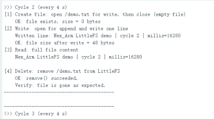
After the program runs, the serial port outputs the file system mount result, test file write result, file content, and the root directory file list. Subsequently, at regular intervals, the serial port continues to output whether the test file currently exists and its size.
2.7.6 Program Analysis
The test file path, file system status flag, and periodic reporting interval are defined at the beginning of the file. Subsequent operations, whether writing files, reading files, or performing periodic checks, are executed around the test file /demo.txt.
namespace {
constexpr const char* TEST_FILE = "/demo.txt";
bool g_fs_ready = false;
unsigned long g_last_report_ms = 0;
constexpr unsigned long REPORT_INTERVAL_MS = 3000;
}
The function
register_system_task()is the starting point of the entire file system experiment. The program first mounts LittleFS. If the mounting fails, it returns directly. After a successful mounting, it executes the three operations of writing a file, reading a file, and traversing the root directory in sequence.
void register_system_task(esp_event_loop_handle_t *event_loop)
{
    (void)event_loop;

    Serial.begin(115200);
    delay(100);

    g_fs_ready = LittleFS.begin(true);
    if (!g_fs_ready) {
        Serial.println("LittleFS mount failed.");
        return;
    }

    Serial.println("FLASH(LittleFS) demo started.");
    write_demo_file();
    read_demo_file();
    list_root_files();
}
The function
write_demo_file()opens /demo.txt in write mode. If the file does not exist, it is created automatically. It then writes two lines of test text, and finally closes the file and outputs the write completion message.
void write_demo_file()
{
    File file = LittleFS.open(TEST_FILE, "w");
    if (!file) {
        Serial.println("Failed to open demo file for write.");
        return;
    }

    file.println("Nex_Arm LittleFS demo");
    file.println("This file is created by system_task_handle.cpp");
    file.close();
    Serial.println("Demo file written.");
}
The function
read_demo_file()opens the same file again in read-only mode, and reads the content byte by byte throughwhile (file.available()). Finally, it prints the read result to the serial port.
void read_demo_file()
{
    File file = LittleFS.open(TEST_FILE, "r");
    if (!file) {
        Serial.println("Failed to open demo file for read.");
        return;
    }

    Serial.println("Demo file content:");
    while (file.available()) {
        Serial.write(file.read());
    }
    Serial.println();
    file.close();
}
The function
list_root_files()traverses the files in the root directory in sequence throughopenNextFile()and outputs the file names and sizes. This provides a direct visual confirmation that the newly created test file has been written to the Flash.
void list_root_files()
{
    File root = LittleFS.open("/");
    if (!root) {
        Serial.println("Failed to open LittleFS root.");
        return;
    }

    Serial.println("LittleFS root files:");
    File file = root.openNextFile();
    while (file) {
        Serial.print("  ");
        Serial.print(file.name());
        Serial.print(" (");
        Serial.print(file.size());
        Serial.println(" bytes)");
        file = root.openNextFile();
    }
}
The function
system_loop_handler()in the main loop is responsible for periodically checking whether the file still exists. Only when the file system has been mounted successfully does the program reopen the test file every 3 seconds and output its current size.
void system_loop_handler(void)
{
    if (!g_fs_ready) {
        delay(100);
        return;
    }

    unsigned long now = millis();
    if (now - g_last_report_ms >= REPORT_INTERVAL_MS) {
        g_last_report_ms = now;

        File file = LittleFS.open(TEST_FILE, "r");
        if (file) {
            Serial.print("Demo file still exists, size = ");
            Serial.print(file.size());
            Serial.println(" bytes");
            file.close();
        } else {
            Serial.println("Demo file not found.");
        }
    }

    delay(10);
}
2.8 Wi-Fi Programming Operations
2.8.1 Project Introduction
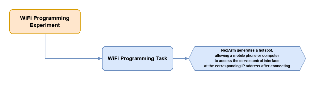
This experiment configures the ESP32 to work in AP mode, creating a hotspot and starting a web server to control the target positions of six bus servos through a browser. The program caches the current servo positions in an array. It sends control requests via web sliders and then calls the servo drive interface to complete the execution of actions.
2.8.2 Program Flow
2.8.3 Module Description
The Wi-Fi module of the ESP32 microcontroller is one of its core wireless communication features. It has a built-in Wi-Fi controller that complies with the IEEE 802.11 b/g/n standard and supports the 2.4 GHz frequency band, with a maximum data transmission rate of up to 150 Mbps. This module supports three working modes: Station mode, Access Point mode, and Station and Access Point coexistence mode. In Station mode, the ESP32 acts as a client connected to an existing wireless network. In Access Point mode, the ESP32 itself acts as a hotspot for other devices to connect. In the coexistence mode, it can take on both roles simultaneously, flexibly adapting to complex network topologies. The Wi-Fi module has an integrated complete TCP/IP protocol stack, supporting common network protocols such as DHCP, DNS, HTTP, HTTPS, and MQTT. Developers can use high-level APIs provided by ESP-IDF or the Arduino framework to quickly implement network connection, data transmission, and cloud platform integration.
2.8.4 Program Upload
Locate the folder 08 Wi-Fi Programming Operations\WiFi_Test inside the 02 Program Source Code directory under the same path as this document. Open the file WiFi_Test.ino. Refer to 2.1.6 Arduino Program Upload for the detailed upload steps.
2.8.5 Program Outcome
After the program runs, the serial port outputs the hotspot name, password, and access address.
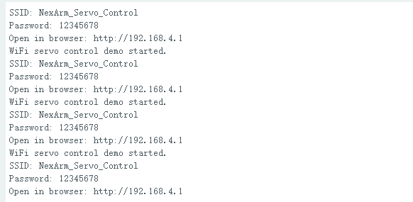
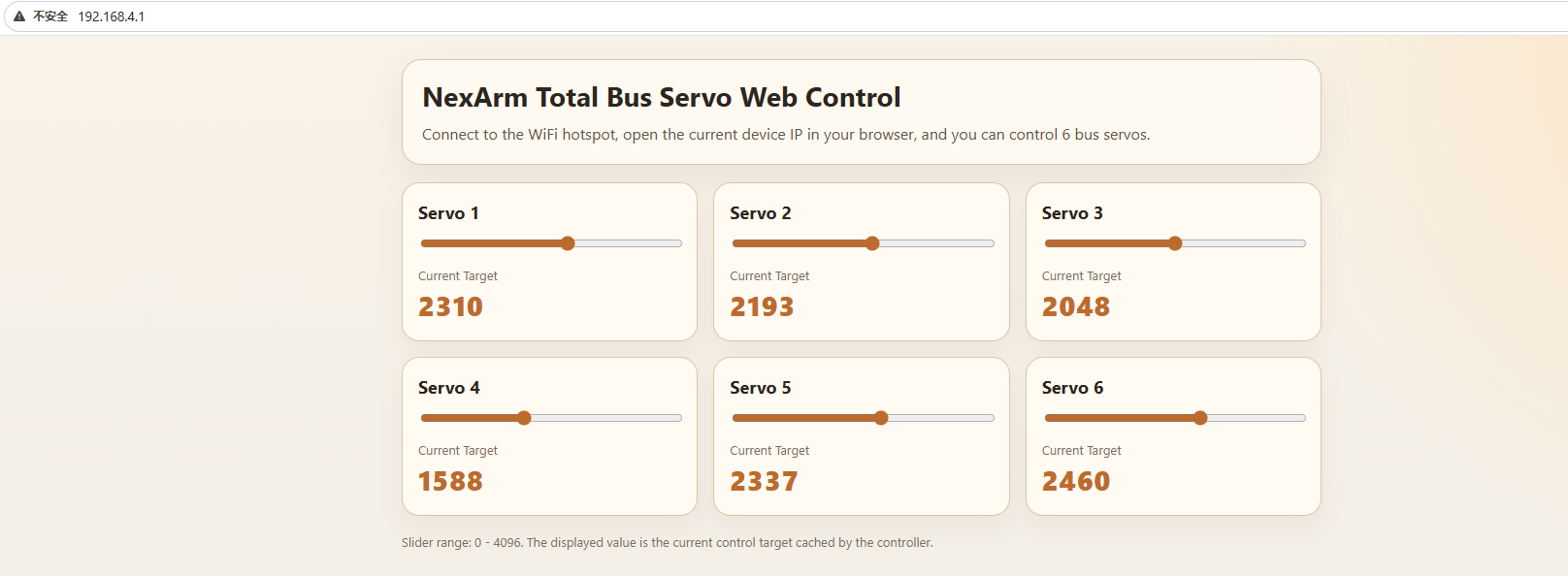
Connect a mobile phone or computer to the hotspot, and open the corresponding IP address http://192.168.4.1 in a browser. The 6-way servo control page is displayed. When the sliders are dragged, the servos move to the specified target positions.
2.8.6 Program Analysis
The hotspot name, password, number of servos, default position, and web server object are defined at the beginning of the main program. The
g_servo_positionsarray is used to cache the current target positions of the six servos. Both webpage reading and servo control are executed around this array.
namespace {
constexpr const char* AP_SSID = "NexArm_Servo_Control";
constexpr const char* AP_PASS = "12345678";
constexpr uint16_t SERVO_MIN_POS = 0;
constexpr uint16_t SERVO_MAX_POS = 4096;
constexpr uint8_t SERVO_COUNT = 6;
constexpr int16_t SERVO_SPEED = 0;
constexpr uint16_t SERVO_DEFAULT_POS = 2048;

WebSender g_server(80);
uint16_t g_servo_positions[SERVO_COUNT] = {
    SERVO_DEFAULT_POS,
    SERVO_DEFAULT_POS,
    SERVO_DEFAULT_POS,
    SERVO_DEFAULT_POS,
    SERVO_DEFAULT_POS,
    SERVO_DEFAULT_POS
};
}
The webpage interface is written directly in the
INDEX_HTMLstring. After the page loads, six sliders are dynamically generated. When a slider changes, a control request is sent to the ESP32 viafetch('/set?...'). Therefore, the browser itself serves as the upper computer interface for this experiment.
const char INDEX_HTML[] PROGMEM = R"HTML(
  <script>
    const SERVO_COUNT = 6;
    const grid = document.getElementById('servoGrid');
    const timers = new Array(SERVO_COUNT).fill(null);

    for (let i = 1; i <= SERVO_COUNT; i++) {
      const card = document.createElement('div');
      card.className = 'card';
      card.innerHTML = `
        <div class="servo-title">Servo ${i}</div>
        <input class="slider" id="slider-${i}" type="range" min="0" max="4096" step="1" value="2048">
        <div class="current-label">Current Target</div>
        <div class="current-value" id="value-${i}">2048</div>
      `;
      grid.appendChild(card);

      const slider = document.getElementById(`slider-${i}`);
      const label = document.getElementById(`value-${i}`);
      slider.addEventListener('input', () => {
        label.textContent = slider.value;
        clearTimeout(timers[i - 1]);
        timers[i - 1] = setTimeout(() => {
          fetch(`/set?id=${i}&pos=${slider.value}`).catch(() => {});
        }, 40);
      });
    }
  </script>
)HTML";
The function
register_system_task()is responsible for hardware and network initialization. The program first opens the servo serial port, sets the ESP32 to AP mode, configures a static IP, creates a hotspot, registers HTTP routes, and starts the WebServer.
void register_system_task(esp_event_loop_handle_t *event_loop)
{
    (void)event_loop;

    Serial.begin(115200);
    delay(100);

    servo.begin(Serial1, 1000000, 16, 17);

    WiFi.mode(WIFI_AP);
    IPAddress local_ip(192, 168, 4, 1);
    IPAddress gateway(192, 168, 4, 1);
    IPAddress subnet(255, 255, 255, 0);
    WiFi.softAPConfig(local_ip, gateway, subnet);

    if (WiFi.softAP(AP_SSID, AP_PASS)) {
        Serial.println("WiFi servo control demo started.");
        Serial.print("SSID: ");
        Serial.println(AP_SSID);
        Serial.print("Password: ");
        Serial.println(AP_PASS);
        Serial.print("Open in browser: http://");
        Serial.println(WiFi.softAPIP());
    } else {
        Serial.println("Failed to start WiFi AP.");
    }

    g_server.on("/", HTTP_GET, handleRoot);
    g_server.on("/positions", HTTP_GET, handlePositions);
    g_server.on("/set", HTTP_GET, handleSet);
    g_server.begin();
}
Data is exchanged between the webpage and the controller through HTTP interfaces. The home page route returns the complete webpage, and the
/positionsroute returns JSON data. This enables the browser to read the currently cached target positions of the servos.
String buildPositionsJson()
{
    String json = "{\"p\":[";
    for (uint8_t i = 0; i < SERVO_COUNT; ++i) {
        if (i > 0) {
            json += ",";
        }
        json += String(g_servo_positions[i]);
    }
    json += "]}";
    return json;
}

void handleRoot()
{
    g_server.send_P(200, "text/html; charset=utf-8", INDEX_HTML);
}

void handlePositions()
{
    g_server.send(200, "application/json", buildPositionsJson());
}
The function
handleSet()is responsible for the actual control logic. The function first checks whether the parameters are complete, and then checks whether the servo ID is out of range. Afterward, it constrains the target position range, and finally callsservo.write_pos_ex()to write the position to the specified servo.
void handleSet()
{
    if (!g_server.hasArg("id") || !g_server.hasArg("pos")) {
        g_server.send(400, "application/json", "{\"ok\":false,\"msg\":\"missing args\"}");
        return;
    }

    int id = g_server.arg("id").toInt();
    int pos = g_server.arg("pos").toInt();

    if (id < 1 || id > SERVO_COUNT) {
        g_server.send(400, "application/json", "{\"ok\":false,\"msg\":\"bad id\"}");
        return;
    }

    pos = constrain(pos, SERVO_MIN_POS, SERVO_MAX_POS);
    g_servo_positions[id - 1] = static_cast<uint16_t>(pos);
    servo.write_pos_ex(static_cast<uint8_t>(id), 0, SERVO_SPEED, static_cast<int16_t>(pos));

    g_server.send(200, "application/json", "{\"ok\":true}");
}
After the server starts,
handleClient()must be continuously called in the main loop to process browser requests. This means that whether the webpage control responds in a timely manner depends on the continuous running ofsystem_loop_handler().
void system_loop_handler(void)
{
    g_server.handleClient();
    delay(2);
}
2.9 ADC Voltage Reading
2.9.1 Project Introduction
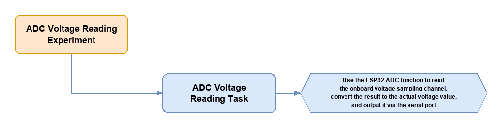
This experiment uses the ADC function of the ESP32 to read the onboard voltage sampling channel, converts the result into the actual voltage value, and outputs it through the serial port. A simple moving average filter is added to the program to make the voltage readings more stable, facilitating the observation of battery voltage changes.
2.9.2 Program Flow
2.9.3 Module Description
The ADC module of the ESP32 microcontroller is an important functional unit for analog signal acquisition. It features two independent successive approximation register, or SAR, ADC controllers named ADC1 and ADC2. These controllers support up to 18 analog input channels distributed across multiple GPIO pins. The module supports four configurable resolution modes, including 9-bit, 10-bit, 11-bit, and 12-bit. In the 12-bit resolution mode, it converts an analog input signal of 0 to 3.3 V into a digital value of 0 to 4095, meeting the requirements of application scenarios with different precision needs. The ADC module has a built-in programmable attenuator, supporting four gain attenuation settings of 0 dB, 2.5 dB, 6 dB, and 11 dB. By adjusting the attenuation coefficient, the effective measurement voltage range can be expanded flexibly, allowing the measurement of input signals up to approximately 3.9 V.
2.9.4 Program Upload
Locate the folder 09 ADC Voltage Reading\ADC_Read inside the 02 Program Source Code directory under the same path as this document. Open the file ADC_Read.ino. Refer to 2.1.6 Arduino Program Upload for the detailed upload steps.
2.9.5 Program Outcome
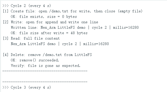
After the program runs, the serial port outputs the current voltage value once per second. The output includes both the millivolt value and the converted volt value, making it easy to directly observe changes in the power supply voltage.
2.9.6 Program Analysis
The voltage sampling object and the print interval are defined in the anonymous namespace at the beginning of the main program. The subsequent main loop only needs to check against
PRINT_INTERVAL_MSto determine whether the next output time has been reached.
namespace {
Bat_t g_bat;
unsigned long g_last_print_ms = 0;

constexpr unsigned long PRINT_INTERVAL_MS = 1000;
}
The function
register_system_task()is responsible for initializing the serial port and the voltage sampling module. The functionsystem_loop_handler()continuously callsg_bat.update()to update the latest sampling value, and outputs the calculation result once per second.
void register_system_task(esp_event_loop_handle_t *event_loop)
{
    (void)event_loop;

    Serial.begin(115200);
    delay(100);

    g_bat.begin();

    Serial.println("ADC voltage demo started.");
    Serial.println("Reading battery voltage every 1 second.");
}

void system_loop_handler(void)
{
    unsigned long now = millis();
    g_bat.update();

    if (now - g_last_print_ms >= PRINT_INTERVAL_MS) {
        g_last_print_ms = now;

        int voltage_mv = g_bat.get_voltage();
        Serial.print("Battery voltage: ");
        Serial.print(voltage_mv);
        Serial.print(" mV (");
        Serial.print(voltage_mv / 1000.0f, 2);
        Serial.println(" V)");
    }

    delay(10);
}
The class
Bat_tdefines the filter window size, cache area, and calibration structure in the header file. Thefilter_bufarray here is used to store the latest sampling results, and the subsequent program calculates the average of these data.
#define WINDOWS_SIZE 10

class Bat_t {
public:
    void begin(void);
    void update(void);
    int get_voltage(void);

private:
    uint8_t filter_index = 0;
    int voltage;
    int filter_buf[WINDOWS_SIZE] = {0};
    esp_adc_cal_characteristics_t adc_chars;
};
In
Bat_t::begin(), the ADC channel attenuation parameters are configured first, and thenesp_adc_cal_characterize()is called to establish calibration information. Finally,update()is executed once so that the first voltage value is obtained after the system starts.
void Bat_t::begin()
{
    adc1_config_channel_atten(ADC_PIN, ADC_ATTEN);
    esp_adc_cal_characterize(ADC_UNIT_1, ADC_ATTEN, ADC_WIDTH, DEFAULT_VREF, &adc_chars);
    update();
}
The function
Bat_t::update()is the core function for sampling. The program first reads the raw ADC value, and then converts it into a millivolt value. Because a voltage divider circuit is used on the board, the value is multiplied by11.0fto restore the actual input voltage. Finally, the value is written to the filter cache and the average value is calculated.
void Bat_t::update()
{
    int raw = adc1_get_raw(ADC_PIN);
    int samples_voltage = esp_adc_cal_raw_to_voltage(raw, &adc_chars);
    samples_voltage = (int)(11.0f * (float)samples_voltage);
    filter_buf[filter_index] = samples_voltage;
    filter_index = (filter_index + 1) % WINDOWS_SIZE;

    int sum = 0;
    if(filter_buf[WINDOWS_SIZE - 1] != 0) {
        for (uint8_t i = 0; i < WINDOWS_SIZE; i++) sum += filter_buf[i];
        voltage = sum / WINDOWS_SIZE;
    }
}
The function
get_voltage()only returns the filtered voltage result to the upper-level caller. After obtaining this result, the main loop formats and outputs it in both millivolts and volts.
int Bat_t::get_voltage()
{
    return voltage;
}