7. Peripheral Control Basics
7.1 Program Upload Instructions - Must Read
Note
Assembly tutorials for NexArm matching peripherals are available in the link 03 Assembly Videos.
Connect NexArm to the computer using a Type-C data cable.
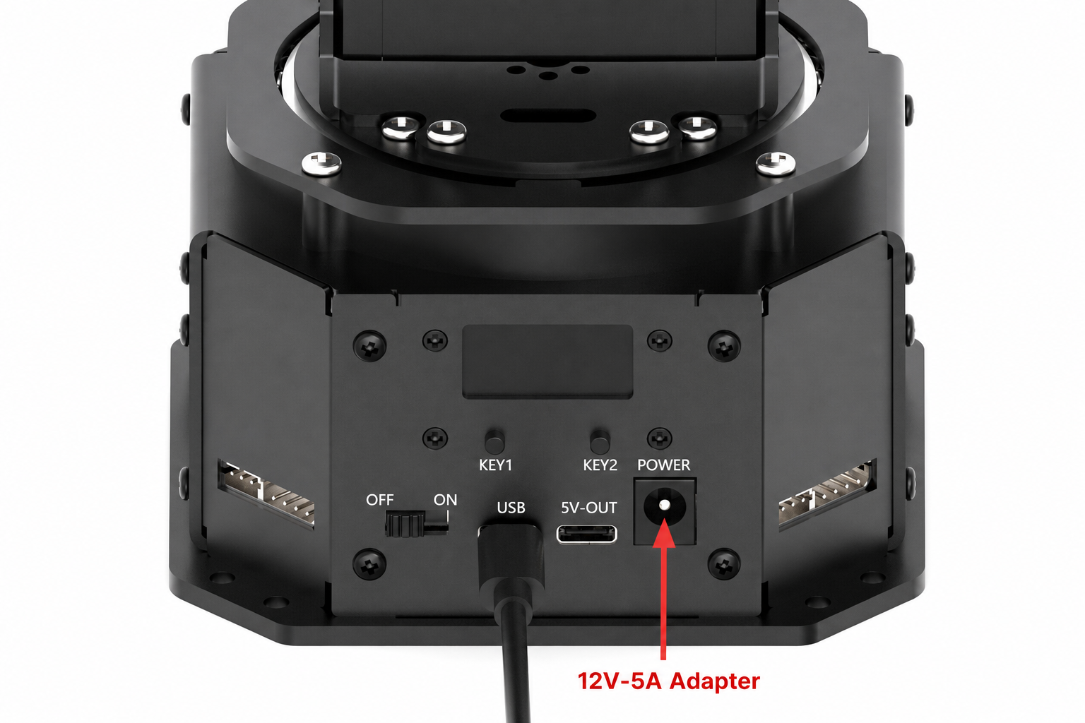
Open the corresponding .ino program file inside the 02 Source Code folder under the same directory path as this document.

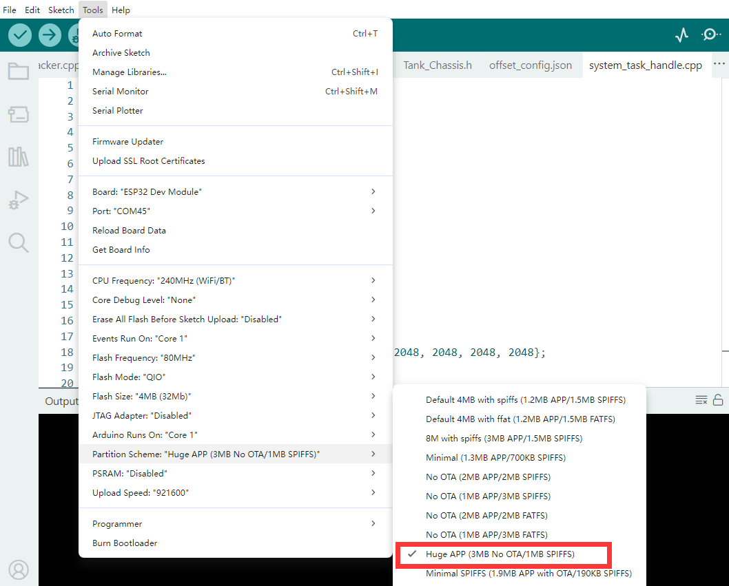
Select the development board model as illustrated in the image below.

Click Tools in the menu bar and configure the corresponding ESP32 development board options according to the following illustration:
Click the compile button
 first, and then click the upload button
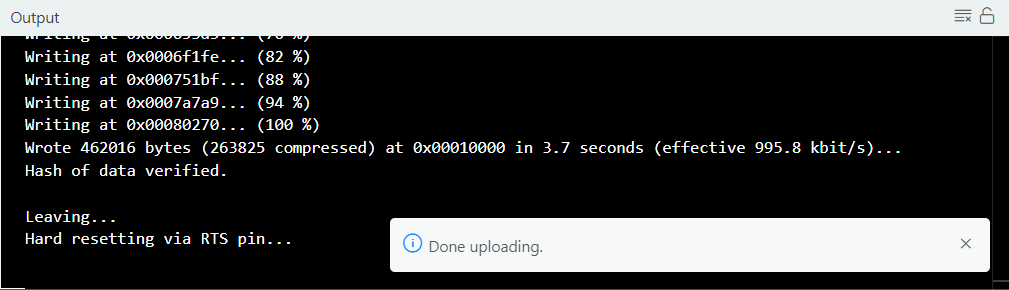
  . The output box at the bottom of the software, displaying the interface below, indicates that the program has been downloaded successfully:
7.2 Introduction to ESP-NOW
7.2.1 ESP-NOW Overview
ESP-NOW is a connectionless, low-power, short-data communication protocol developed by Espressif Systems based on the Wi-Fi physical layer and data link layer. Unlike traditional Wi-Fi communication, ESP-NOW does not rely on a router and eliminates the need to establish a connection or acquire an IP address. Instead, direct peer-to-peer or one-to-many communication is achieved via the MAC address of the device.
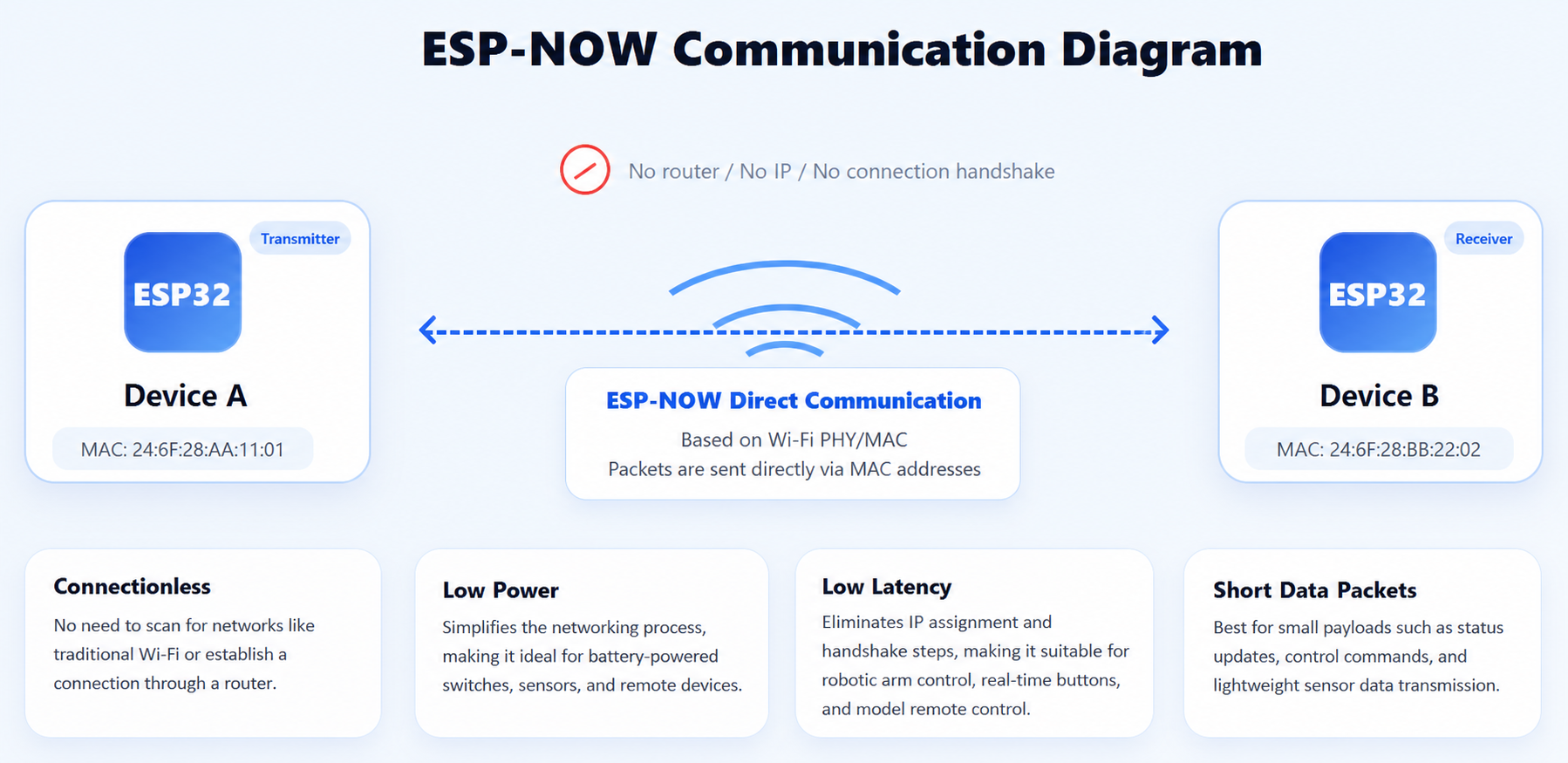
By eliminating processes such as network scanning, association, and IP assignment, ESP-NOW delivers millisecond-level low latency along with low power consumption. This makes the protocol highly suitable for battery-powered wireless control, sensor data transmission, and real-time remote control scenarios. Although the single packet payload size is limited to within 250 bytes, the supported AES encryption mechanism effectively safeguards communication security, making it a wireless communication solution that strikes an optimal balance among transmission distance, response speed, and power consumption.
7.2.2 Operating Principle
The underlying layer of ESP-NOW still operates on the 2.4GHz Wi-Fi physical layer. However, it bypasses the traditional TCP/IP protocol stack and avoids procedures required by standard Wi-Fi, such as scanning hotspots, connecting to routers, and obtaining IP addresses. Instead, short-data communication between devices is executed directly based on 802.11 data frames. The transmitting end only requires the MAC address of the target device to encapsulate and send data directly to the receiving end, which parses and processes the frame upon receipt.
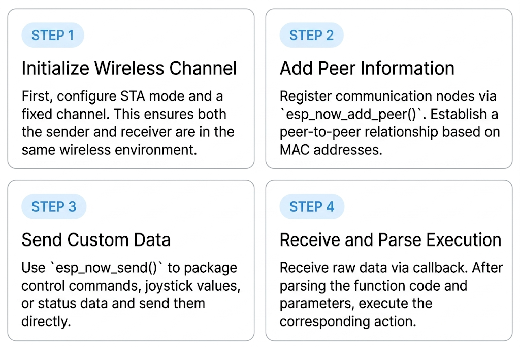
The basic workflow is outlined below. First, the primary control chip initializes the Wi-Fi module and sets the operating channel. Next, the communication peer is added via esp_now_add_peer() to establish peer node information. Following this, the transmitter calls esp_now_send() to deliver the data frame to a specified MAC address or broadcast address, while the receiver obtains the incoming data content in real time via a registered callback function. When the application layer requires status synchronization, button control, or transparent data transmission, data parsing and the corresponding operations are executed directly within the receiving callback.
Compared to traditional Wi-Fi communication, ESP-NOW omits the connection establishment process, thereby delivering faster response speeds. Particularly in scenarios involving robotic arm control, remote controller synchronization, and status broadcasting, this mechanism of immediate transmission after initialization significantly reduces communication latency, enhancing real-time performance and system stability.
7.2.3 Communication Modes
ESP-NOW supports multiple common communication modes, enabling both point-to-point communication and one-to-many communication. In point-to-point mode, the transmitter sends data to a fixed target MAC address, which is ideal for directional control between a remote controller and a single device. This mode provides a clear communication link and straightforward data management, making it suitable for control tasks that demand high reliability.
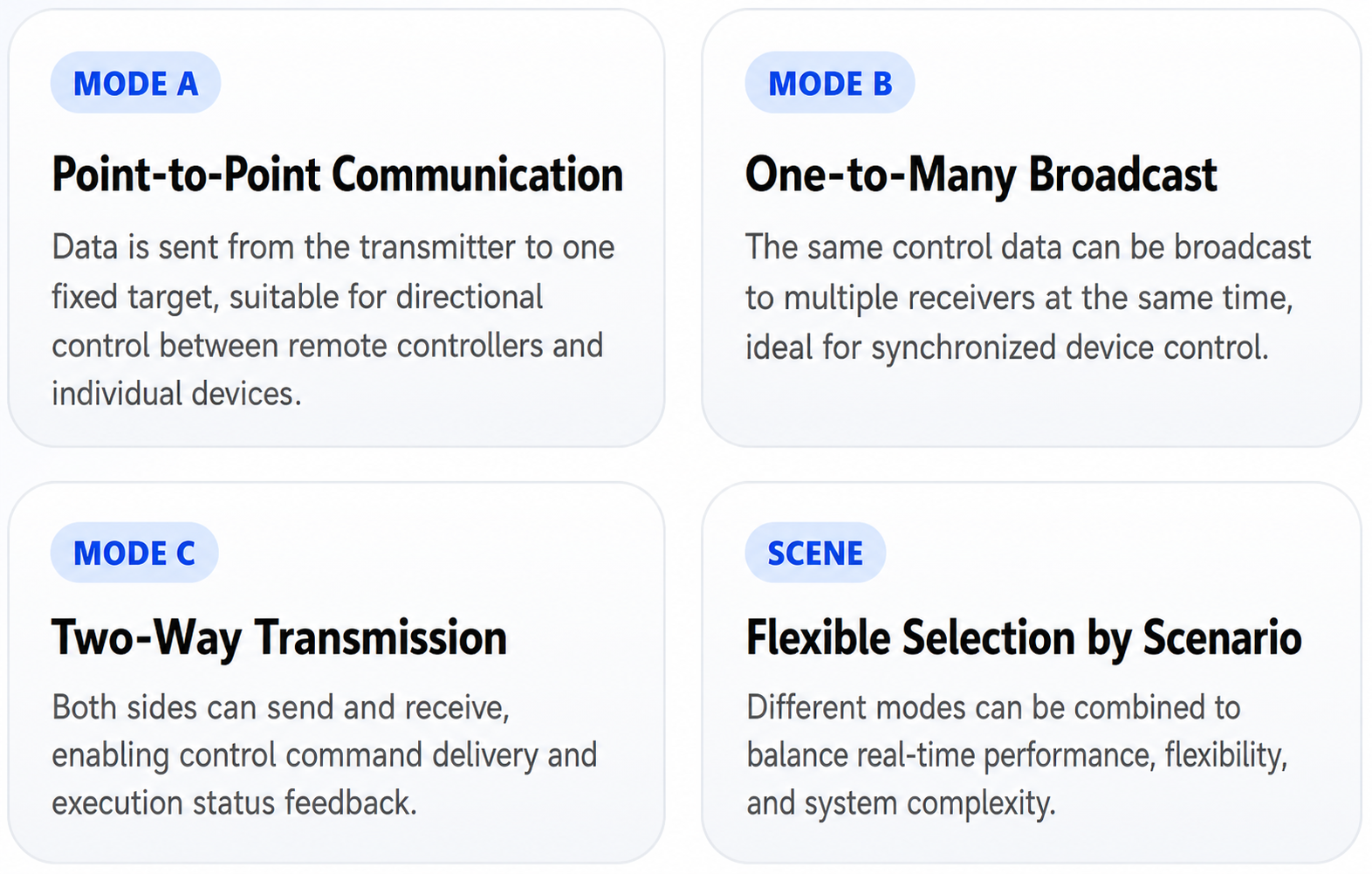
In one-to-many mode, the transmitter can utilize a broadcast MAC address to send identical data to multiple devices. As long as multiple receivers operate on the same channel and remain in a receivable state, the data can be received simultaneously. This approach is commonly used for multi-device synchronized control, such as a synchronizer dispatching motion commands to multiple robotic arms simultaneously, or a master control node uniformly broadcasting status and control information.
In addition to unidirectional transmission, ESP-NOW supports bidirectional communication. This means a device can function as both a transmitter and a receiver, allowing both parties to send and receive data to each other. Through this method, a closed-loop control structure of the master sending control commands and the device returning execution status can be implemented. In practical applications, different modes such as unicast, broadcast, or bidirectional interaction can be selected based on control requirements to balance real-time performance, flexibility, and system complexity.
7.2.4 Data Structure and Restrictions
The data transmitted by ESP-NOW consists essentially of custom byte arrays, allowing developers to design communication protocols based on specific application scenarios. For instance, button states, joystick values, coordinate data, servo positions, and control commands can be encapsulated into structures or byte streams before transmission via ESP-NOW. The receiver simply parses the incoming data based on the predefined format to accurately reconstruct the original control commands from the transmitter.
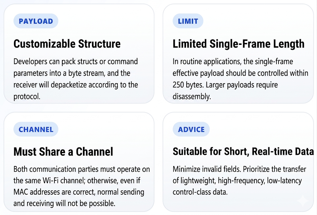
During operation, single-frame data length restrictions must be taken into account. Typically, the payload length per transmission must be kept within 250 bytes. Exceeding this limit requires data packet fragmentation, otherwise transmission failures or data anomalies will occur. Additionally, because ESP-NOW operates on a fixed channel, the transmitter and receiver must reside on the same Wi-Fi channel. Otherwise, data transceiver functions will fail even if the MAC address is correct.
Additionally, ESP-NOW is better suited for transmitting short, real-time data rather than continuous transmissions of large files or long data streams. For high-frequency control applications, simplifying the data structure, reducing invalid fields, and minimizing the data volume per transmission are highly recommended to effectively decrease transmission latency and boost communication efficiency and system response speed.
7.2.5 Security Mechanisms
ESP-NOW supports a certain degree of communication security protection. Its core mechanism relies on the AES-128 encryption algorithm for encrypted data transmission. Developers can configure a Primary Master Key (PMK) and a Local Master Key (LMK) for the devices. Once encryption is enabled, effective communication is restricted to devices possessing the correct keys, thereby preventing unauthorized devices from receiving or forging data.

In practical applications involving only experimental testing or functional verification in a local environment, unencrypted broadcast communication can be utilized first due to its simple configuration and convenient debugging. In scenarios involving formal control, device linkage, or risks of external interference, prioritizing paired communication with encryption enabled is recommended to enhance communication security and reliability.
While ESP-NOW security features protect data transmission, robust communication security requires more than encryption alone. It should be combined with measures such as fixed communication channels, restricted peer MAC addresses, and rationally designed data protocols. The stable operation of the entire wireless control system can be better guaranteed only when the link configuration, data format, and device management are well standardized.
7.3 ESP-NOW Control
7.3.1 Project Introduction
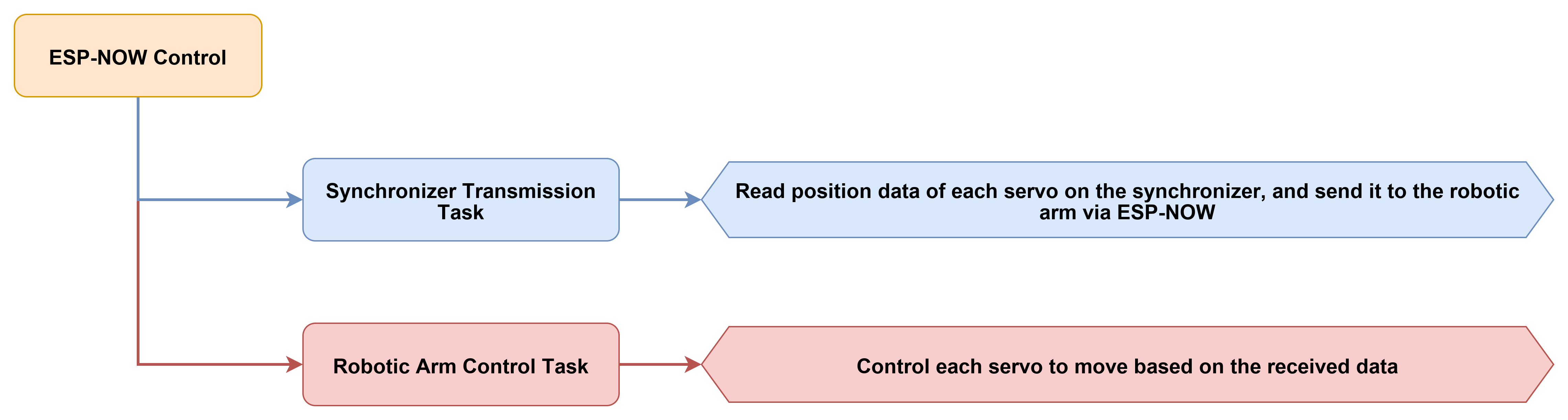
This section demonstrates wireless control between a robotic arm and a synchronizer using ESP-NOW. The synchronizer program is responsible for reading the current positions of the 6-channel servos and periodically transmitting this position data to the target robotic arm via ESP-NOW. The robotic arm program handles receiving the synchronization data, executing servo mapping, and performing motions, while supporting synchronization switch control and OLED status display.
7.3.2 Program Flow
7.3.3 Program Download
Robotic Arm Program Download
Locate the 02 Source Code folder in the same directory as this document, and find the program under Synchronizer Joystick Control\NexArm.zip for downloading. This program is used to receive ESP-NOW data sent by the synchronizer and control the robotic arm to execute synchronized actions. For specific download steps, refer to 7.1 Program Download Instructions - Must Read.
Synchronizer Program Download
Locate the 02 Source Code folder in the same directory as this document, and find the program under Synchronizer Joystick Control\Synchronizer.zip for downloading. For specific download steps, refer to 7.1 Program Download Instructions - Must Read.
7.3.4 Program Outcome
Once both programs are successfully downloaded, the devices enter the same ESP-NOW channel upon power-up. The synchronizer continuously reads its own 6-channel servo positions and transmits them to the external device. After synchronization mode is enabled, the robotic arm receives this position data and executes local servo linkage. The robotic arm OLED displays the current end-effector pose in real time, and the synchronizer serial port outputs the transmitted servo position data to facilitate monitoring of the wireless synchronization effect.
7.3.5 Program Analysis
Robotic Arm Analysis
The robotic arm program first defines the runtime states required for ESP-NOW control, including the protocol parsing object, parameter storage object, current channel, global acceleration, synchronization switch, OLED refresh time, battery refresh time, and the most recent servo feedback time. These variables collectively determine the basic configuration and status cache during wireless synchronization runtime.
CommProtocol_t at32_protocol;
Preferences prefs;

uint8_t global_channel = DEFAULT_ESPNOW_CHANNEL;
uint8_t global_acc = 245;
bool espnow_sync_enabled = false;

uint32_t last_oled_refresh_ms = 0;
uint32_t last_bat_refresh_ms = 0;
uint32_t button_enable_ms = 0;

int16_t g_last_servo_positions[6] = {2048, 2048, 2048, 2048, 2048, 2048};
uint32_t g_last_servo_feedback_ms = 0;
The functions
load_config()andsave_config()handle saving and restoring ESP-NOW-related parameters, such as the current channel and synchronization acceleration. This allows the device to retain previously configured communication parameters upon power cycling, eliminating the need for reconfiguration.
void save_config()
{
    prefs.begin("robot_cfg", false);
    prefs.putUChar("channel", global_channel);
    prefs.putUChar("acc", global_acc);
    prefs.end();
}

void load_config()
{
    prefs.begin("robot_cfg", true);
    global_channel = prefs.getUChar("channel", DEFAULT_ESPNOW_CHANNEL);
    global_acc = prefs.getUChar("acc", 245);
    prefs.end();
}
The function
restart_espnow()is utilized to restart ESP-NOW according to the current channel. Upon a successful restart, it re-registers the protocol callback and configures whether the follower arm is permitted to execute synchronized motions based on the current synchronization state. This unifies wireless module initialization and synchronization state control into a single function.
bool restart_espnow()
{
    espnow_ctrl.stop();
    delay(50);

    if (!espnow_ctrl.begin(global_channel)) {
        arm.board.buzzer.set(120, 80, 1, 1000);
        return false;
    }

    espnow_ctrl.register_ops_callback(func_ctrl_callback);
    apply_follow_sync_state(espnow_sync_enabled, false);

    return true;
}
The function
func_ctrl_callback()serves as the core entry point for processing ESP-NOW protocol control packets on the robotic arm side. For control commands such asCMD_COORDINATE_SETandCMD_ARM_MOVE_INC, the program first transmits them transparently to the AT32, then synchronously updates the local pose cache. For commands like setting channels, toggling the synchronization switch, and configuring the paired MAC, processing occurs directly on the local ESP32.
void func_ctrl_callback(PacketTypeDef* self)
{
    uint8_t payload_len = self->elements.length >= 2 ? (uint8_t)(self->elements.length - 2) : 0;

    if (self->elements.id == 0xFF) {
        switch (self->elements.cmd) {
            case CMD_ESPNOW_SYNC_CTRL:
                if (payload_len >= 1) {
                    apply_follow_sync_state(self->elements.args[0] == 1, true);
                }
                break;

            case CMD_COORDINATE_SET:
                servo.tx_frame_write(0xFF, self->elements.cmd, self->elements.args, payload_len);
                update_pose_from_coordinate_set(self->elements.args, payload_len);
                break;
        }
    }
}
The primary synchronization data for ESP-NOW consists of an
ArmPacket_tstructure rather than standard coordinate commands. WithinOnDataRecv(), the receiver verifies whether the length of the incoming data matches the size of this structure. If synchronization mode is enabled, the 6-channel servo positions sent from the master device are cached first, followed by a unified mapping and servo command dispatch within the main loop to prevent transmitting large amounts of serial data directly inside the receive callback.
typedef struct __attribute__((packed)) {
    uint32_t seq;
    int16_t pos[6];
} ArmPacket_t;

if (espnow_ctrl.sync_enabled && len == sizeof(ArmPacket_t)) {
    ArmPacket_t *pkt = (ArmPacket_t*)incomingData;
    for (int i = 0; i < 6; ++i) {
        espnow_ctrl.pending_master_pos[i] = pkt->pos[i];
    }
    espnow_ctrl.pending_sync_apply = true;
}
The functions
mapMasterTeachToFollower()andapplyMasterTeachPositions()map the servo values of the leader arm to the target values of the follower arm, invokingservo.sync_write_pos_speed()collectively to transmit them to the 6-channel servos. Direction and range corrections are incorporated for servo ID 2 and servo ID 6, meaning the synchronization process is not a simple direct copy of the original values.
void EspNow_Ctrl_t::mapMasterTeachToFollower(const int16_t *master_positions, int16_t *target_positions) {
    for (int i = 0; i < 6; i++) {
        int id = i + 1;
        int16_t master_pos = master_positions[i];

        if (id == 2) {
            target_positions[i] = (int16_t)constrain(4096 - (int32_t)master_pos, 0, 4096);
        } else if (id == 6) {
            int32_t delta = (int32_t)master_pos - 2048;
            target_positions[i] = (int16_t)constrain(2833 + delta * 4, 1195, 2833);
        } else {
            target_positions[i] = master_pos;
        }
    }
}
The main loop processes pending synchronization frames first, followed by AT32 feedback packets, buttons, battery status, and OLED refreshes. When the BOOT button is detected, the synchronization mode toggles. Once synchronization mode is enabled, the robotic arm end continuously processes the servo position data sent from the synchronizer and displays the current pose on the OLED.
void system_loop_handler(void)
{
    if (espnow_sync_enabled) {
        espnow_ctrl.processPendingSyncFrame(0);
    }

    pump_at32_feedback();
    arm.board.button.update();
    arm.board.buzzer.update();

    uint32_t now = millis();
    if (now >= button_enable_ms && arm.board.button.is_clicked(0)) {
        toggle_follow_sync();
    }

    if (now - last_oled_refresh_ms >= OLED_REFRESH_INTERVAL_MS) {
        last_oled_refresh_ms = now;
        arm.board.oled.show_status(
            arm.current_pose.x,
            arm.current_pose.y,
            arm.current_pose.z,
            arm.current_pose.pitch,
            arm.current_pose.roll,
            arm.current_pose.claw
        );
    }
}
Synchronizer Analysis
The core data structure of the synchronizer program is
ArmPacket_t, which contains a time sequence numberseqand 6-channel servo positionspos[6]. During each transmission, the program writes the current timestamp intoseqand the read values of the 6 servos into thepos[]array, forming a complete synchronization data packet.
typedef struct __attribute__((packed)) {
    uint32_t seq;
    int16_t pos[6];
} ArmPacket_t;

int16_t last_valid_pos[6] = {2048, 2048, 2048, 2048, 2048, 2048};
The initialization phase begins by starting the serial port and the serial bus servo interface. Next, Wi-Fi is configured to STA mode with a fixed channel, followed by initializing ESP-NOW and adding the broadcast address as the target node. Consequently, the synchronizer broadcasts teaching data directly to the follower robotic arms within the same channel.
WiFi.mode(WIFI_STA);
WiFi.disconnect();

esp_wifi_set_promiscuous(true);
esp_wifi_set_channel(WIFI_CHANNEL, WIFI_SECOND_CHAN_NONE);
esp_wifi_set_promiscuous(false);

if (esp_now_init() != ESP_OK) {
    Serial.println("ESP-NOW Init Error");
    return;
}

esp_now_peer_info_t peerInfo = {};
memcpy(peerInfo.peer_addr, broadcastMac, 6);
peerInfo.channel = WIFI_CHANNEL;
peerInfo.encrypt = false;
esp_now_add_peer(&peerInfo);
Upon completing initialization, the program sequentially disables the torque for servos 1 through 6. This allows the synchronizer to be manually guided during teaching, after which the main loop transmits the read servo positions to the receiver, establishing a hand-guided teaching and wireless synchronization control method.
for (int i = 1; i <= 6; i++) {
    servo.disable_torque(i);
    delay(5);
}
Operating with a transmission period of
SEND_INTERVAL_MS, the main loop reads the current position of each of the 6-channel servos in every cycle. The arraylast_valid_pos[]is updated upon a successful read, whereas the previous valid values are retained if a read fails, preventing individual reading anomalies from causing obvious jumps in the overall synchronization frame.
for (int i = 0; i < 6; i++) {
    int16_t pos = 0;
    ServoStatus_t status = servo.read_pos(i + 1, &pos);

    if (status.error_bits.bit_rx == 0 && status.error_bits.bit_tx == 0 && pos != 0) {
        last_valid_pos[i] = pos;
    }
    delayMicroseconds(200);
}
Once all servo values are prepared, the program writes them into
teachPacket.pos[]and callsesp_now_send()for broadcast transmission. In essence, the synchronizer does not perform any complex parsing, as its primary responsibility is to read servo values, encapsulate the structure, and transmit periodically.
for (int i = 0; i < 6; i++) {
    teachPacket.pos[i] = last_valid_pos[i];
}

esp_now_send(broadcastMac, (uint8_t*)&teachPacket, sizeof(ArmPacket_t));
The synchronizer maintains serial debugging output, printing the currently transmitted 6-channel servo positions at regular intervals. These printed logs allow direct observation of whether the teaching data currently read by the synchronizer is normal, facilitating cross-reference debugging with the actions of the receiving end.
if (currentMillis - lastDebugTime > 500) {
    lastDebugTime = currentMillis;
    Serial.printf("[Teach] Pos: %d %d %d %d %d %d\n",
        teachPacket.pos[0], teachPacket.pos[1], teachPacket.pos[2],
        teachPacket.pos[3], teachPacket.pos[4], teachPacket.pos[5]);
}
7.4 Conveyor Belt Control
7.4.1 Project Introduction
This section demonstrates how to achieve start-stop control using the conveyor belt interface on the controller. Upon powering up, the program sets the conveyor belt speed to 0. Pressing the BOOT button toggles the speed between 100 and 0 while displaying the current operating status on the OLED.
7.4.2 Program Flow

7.4.3 Program Download
Locate the 02 Source Code folder in the same directory as this document, and find the program under Conveyor Belt Control for downloading. For specific download steps, refer to 7.1 Program Download Instructions - Must Read.
7.4.4 Program Outcome
The conveyor belt defaults to a stopped state upon powering up. Pressing the KEY1 (BOOT) button initiates conveyor belt operation at a speed of 20. Pressing the KEY1 button again increments the speed by 20 each time. Pressing the KEY2 (USER) button stops the conveyor belt movement. The OLED simultaneously displays the current speed and operating status.
7.4.5 Program Analysis
The program first includes the Arduino, Wire, and board-level encapsulation header files, configures the main loop task stack size, and defines two button IDs along with the conveyor belt I2C pins. The identifiers
KEY1_IDandKEY2_IDare utilized within the main loop to distinguish between the two buttons. Pins 21 and 22 initialize theWire1bus connecting the conveyor belt driver.
#include "Arduino.h"
#include "Wire.h"
#include "Nex_Arm_Board.h"

SET_LOOP_TASK_STACK_SIZE(4096);

#define KEY1_ID 0
#define KEY2_ID 1
#define CONVEYOR_I2C_SDA_PIN 21
#define CONVEYOR_I2C_SCL_PIN 22
The program creates an
HW_Boardobject and defines the conveyor speed array. The variablenext_speed_indextracks the next speed level for KEY1,current_speedstores the active speed, andconveyor_runningmaintains the operating state. Additionally,oled_readyprevents the display from continuing to refresh if OLED initialization fails.
static HW_Board board;

static const int8_t conveyor_speeds[] = {20, 40, 60, 80, 100};
static const uint8_t conveyor_speed_count = sizeof(conveyor_speeds) / sizeof(conveyor_speeds[0]);

static uint8_t next_speed_index = 0;
static int8_t current_speed = 0;
static bool conveyor_running = false;
static bool oled_ready = false;
The function
show_conveyor_status()handles refreshing the OLED display. If the OLED initialization is unsuccessful, the function returns immediately. Upon successful initialization, the program displays the conveyor belt title, current operating state, and current speed, enabling synchronized display of the status following button operations.
static void show_conveyor_status()
{
    if(!oled_ready) return;

    board.oled.set_custom_text(0, "Conveyor Belt");
    board.oled.set_custom_text(1, conveyor_running ? "KEY2 Status: RUN" : "KEY2  Status: STOP");
    board.oled.set_custom_text(2, String("KEY1 Speed: ") + String(current_speed));
    board.oled.set_custom_text(3, "");
    board.oled.show_custom();
}
The function
run_next_speed()manages the speed loop for KEY1. During each invocation, the program extracts the speed corresponding to the current index from the speed array, increments the index, and applies a modulo operation to achieve a continuous cycle of 20, 40, 60, 80, 100, and back to 20. It then writes this speed to the conveyor belt and refreshes the OLED.
static void run_next_speed()
{
    current_speed = conveyor_speeds[next_speed_index];
    next_speed_index = (next_speed_index + 1) % conveyor_speed_count;
    conveyor_running = true;

    board.conveyor.set_speed(current_speed);
    show_conveyor_status();
}
The function
stop_conveyor()handles the KEY2 stop functionality. It sets the current speed to0, updates the operating status to stopped, and resets the next speed index to0, ensuring that pressing KEY1 after a conveyor belt stop restarts operation from a speed of20.
static void stop_conveyor()
{
    current_speed = 0;
    conveyor_running = false;
    next_speed_index = 0;

    board.conveyor.set_speed(0);
    show_conveyor_status();
}
The initialization phase starts the OLED first, configures the conveyor belt I2C bus using
Wire1.begin(), and then callsboard.conveyor.begin(&Wire1)to initialize the conveyor belt driver. Finally,stop_conveyor()is invoked to guarantee that the conveyor belt defaults to a stopped state upon powering up and displays the stopped status on the OLED.
void setup()
{
    oled_ready = board.oled.begin();

    Wire1.begin(CONVEYOR_I2C_SDA_PIN, CONVEYOR_I2C_SCL_PIN, 100000);
    board.conveyor.begin(&Wire1);

    stop_conveyor();
}
The main loop continuously updates the button statuses. When a KEY1 press is detected, the program invokes
run_next_speed()to switch to the next speed level. When a KEY2 press is detected,stop_conveyor()is called to stop the conveyor belt. The finaldelay(10)reduces the loop frequency to keep button polling stable.
void loop()
{
    board.button.update();

    if(board.button.is_clicked(KEY1_ID)) {
        run_next_speed();
    }

    if(board.button.is_clicked(KEY2_ID)) {
        stop_conveyor();
    }

    delay(10);
}
7.5 Sliding Rail Control
7.5.1 Project Introduction
This section demonstrates how to control a stepper sliding rail’s movement via the stepper interface. Upon power-on, the firmware initializes the rail’s microstepping mode to 0x02 and executes a homing routine. Press the BOOT button to advance the rail by 1,000 steps, or press the USER button to return it to its starting position.
7.5.2 Program Flow

7.5.3 Program Download
Locate the 02 Source Code folder in the same directory as this document, and find the program under Sliding Rail Control for downloading. For specific download steps, refer to 7.1 Program Download Instructions - Must Read.
7.5.4 Program Outcome
After powering up, the sliding rail first completes its subdivision mode configuration and homing operation. Pressing the BOOT button drives the slide forward by 1000 steps. Pressing the USER button executes a homing reset. The OLED displays the current subdivision mode, step details, and the most recent button action.
7.5.5 Program Analysis
The program initially defines the sliding rail subdivision mode, steps per movement, homing wait time, and button guard time. These constants provide a direct overview of the control parameters for the current example, such as a subdivision mode fixed at
0x02and a single movement fixed at1000steps.
constexpr uint8_t kStepperSubdivision = 0x02;
constexpr int32_t kStepperMoveSteps = 1000;
constexpr uint32_t kStepperResetWaitMs = 2000;
constexpr uint32_t kButtonStartupGuardMs = 1200;

uint32_t g_button_enable_ms = 0;
The initialization phase begins by invoking
arm.begin()to complete board-level object initialization. Next,set_subdivision()configures the sliding rail subdivision mode, followed by an immediate execution ofreset()for homing. A fixed delay is incorporated here to allow sufficient time for the sliding rail to home, preventing subsequent actions from starting prematurely.
arm.begin();

arm.board.stepper.set_subdivision(kStepperSubdivision);
arm.board.stepper.reset();
delay(kStepperResetWaitMs);
Upon completing sliding rail initialization, the program clears residual button states, sets the button guard time, and displays the current mode information and button instructions on the OLED. Consequently, the interface is ready upon power-up, directly presenting the BOOT run USER home control scheme.
arm.board.button.update();
arm.board.button.is_clicked(0);
arm.board.button.is_clicked(1);
g_button_enable_ms = millis() + kButtonStartupGuardMs;

arm.board.oled.set_custom_text(0, "Stepper Control");
arm.board.oled.set_custom_text(1, "Subdivision: 0x02");
arm.board.oled.set_custom_text(2, "Move: 1000 steps");
arm.board.oled.set_custom_text(3, "BOOT run USER home");
arm.board.oled.show_custom();
The control logic within the main loop is straightforward. Pressing the BOOT button calls
stepper.move(kStepperMoveSteps)to execute the fixed number of steps. Pressing the USER button callsstepper.reset()to return the slide to its initial position. The OLED prompt information is updated synchronously following each action.
if (millis() >= g_button_enable_ms && arm.board.button.is_clicked(0)) {
    arm.board.stepper.move(kStepperMoveSteps);
    arm.board.oled.set_custom_text(3, "BOOT moved 1000");
}

if (millis() >= g_button_enable_ms && arm.board.button.is_clicked(1)) {
    arm.board.stepper.reset();
    arm.board.oled.set_custom_text(3, "USER reset home");
}
This program separates subdivision mode configuration and motion control into two distinct phases. The subdivision mode is configured only once during initialization. Subsequently, regardless of whether a movement or homing is executed, this parameter is not repeatedly modified. This approach prevents frequent changes to the driver configuration during runtime, ensuring that sliding rail actions are consistently executed based on the same set of stepping parameters.
arm.board.stepper.set_subdivision(kStepperSubdivision);
arm.board.stepper.reset();
delay(kStepperResetWaitMs);
The main loop continuously invokes
arm.board.oled.show_custom()at the end of its cycle, ensuring the interface remains on the current custom page during sliding rail movements. Combined with overwriting the fourth line of text upon a button press, this approach provides clear visibility into whether the most recently executed action was “Move 1000 Steps” or “Return to Initial Position.”
void system_loop_handler(void)
{
    arm.board.button.update();
    arm.board.buzzer.update();
    arm.board.bat.update();

    if (millis() >= g_button_enable_ms && arm.board.button.is_clicked(0)) {
        arm.board.stepper.move(kStepperMoveSteps);
        arm.board.oled.set_custom_text(3, "BOOT moved 1000");
    }

    if (millis() >= g_button_enable_ms && arm.board.button.is_clicked(1)) {
        arm.board.stepper.reset();
        arm.board.oled.set_custom_text(3, "USER reset home");
    }

    arm.board.oled.show_custom();
}
7.6 Motor Speed Control
7.6.1 Project Introduction
Motor speed adjustment via the controller’s motor interface is covered in this section. Three distinct velocity settings—Slow, Medium, and Fast—are defined within the program. Pressing the USER button cycles through these presets, whereas the BOOT button controls motor starting and stopping.
7.6.2 Program Flow

7.6.3 Program Download
Locate the 02 Source Code folder in the same directory as this document, and find the program under Motor Speed Control for downloading. For specific download steps, refer to 7.1 Program Download Instructions - Must Read.
7.6.4 Program Outcome
Upon power-up, the motor remains stopped by default, and the OLED displays the current speed level as Medium. Pressing the USER button cycles the speed level among Slow, Medium, and Fast. Pressing the BOOT button initiates motor operation at the selected speed level, while a subsequent press stops the motor.
7.6.5 Program Analysis
The program first defines the speed profile structure via
MotorSpeedProfileand utilizes an array to store three sets of speed parameters. Concurrently, variables for the current speed index, button enable time, and motor operating state are defined to identify the active speed level and indicate whether velocity output is currently active.
struct MotorSpeedProfile {
    const char* name;
    int8_t speed;
};

constexpr MotorSpeedProfile kSpeedProfiles[] = {
    {"Slow", 60},
    {"Medium", 100},
    {"Fast", 127},
};

uint8_t g_speed_profile_index = 1;
uint32_t g_button_enable_ms = 0;
bool g_motor_running = false;
Based on whether the motor is currently running,
apply_motor_output()determines whether to output the active speed level or a velocity of0. Meanwhile,refresh_oled_status()displays the active speed level, operating state, and the most recent action prompt on the OLED, ensuring the interface remains continuously synchronized with the actual control state.
void apply_motor_output()
{
    int8_t speed = g_motor_running ? kSpeedProfiles[g_speed_profile_index].speed : 0;
    arm.board.motor.set_speed(speed, speed, speed, speed);
}

void refresh_oled_status(const char* action_text)
{
    arm.board.oled.set_custom_text(0, "Motor Speed Ctrl");
    arm.board.oled.set_custom_text(1, String("Speed: ") + kSpeedProfiles[g_speed_profile_index].name);
    arm.board.oled.set_custom_text(2, g_motor_running ? "Motor: Running" : "Motor: Stopped");
    arm.board.oled.set_custom_text(3, action_text);
    arm.board.oled.show_custom();
}
The initialization phase begins by invoking
arm.begin(), followed by an immediate execution ofapply_motor_output()to ensure the motor remains stopped upon power-up. Subsequently, residual button states are cleared and the button guard time is set. Finally, button function prompts are displayed on the OLED.
arm.begin();

apply_motor_output();

arm.board.button.update();
arm.board.button.is_clicked(0);
arm.board.button.is_clicked(1);
g_button_enable_ms = millis() + kButtonStartupGuardMs;

refresh_oled_status("BOOT run / USER speed");
The function
toggle_motor_state()handles toggling motor activation and deactivation, whereasswitch_speed_profile()manages switching speed levels. Invoking these two functions within the main loop based on respective button presses establishes the complete BOOT for operation, USER for speed interaction scheme.
void toggle_motor_state()
{
    g_motor_running = !g_motor_running;
    apply_motor_output();
    refresh_oled_status(g_motor_running ? "BOOT start motor" : "BOOT stop motor");
}

void switch_speed_profile()
{
    g_speed_profile_index = (g_speed_profile_index + 1) % (sizeof(kSpeedProfiles) / sizeof(kSpeedProfiles[0]));
    apply_motor_output();
    refresh_oled_status("USER switched speed");
}
Motor output utilizes the
set_speed(speed, speed, speed, speed)format to uniformly set all four motors to the same speed. Consequently, the primary focus of the example is neither differential nor directional control. Instead, it demonstrates how to switch speed levels and output the corresponding values to the motor interfaces.
void apply_motor_output()
{
    int8_t speed = g_motor_running ? kSpeedProfiles[g_speed_profile_index].speed : 0;
    arm.board.motor.set_speed(speed, speed, speed, speed);
}
Beyond responding to both button presses, the main loop retains the routine refresh logic for the buzzer, battery, and OLED. Rather than updating the interface only upon a button press, the program continuously maintains a baseline peripheral polling structure in the background. This approach ensures that the speed level and operating state displays remain constantly updated.
void system_loop_handler(void)
{
    arm.board.button.update();
    arm.board.buzzer.update();
    arm.board.bat.update();

    uint32_t now = millis();

    if (now >= g_button_enable_ms && arm.board.button.is_clicked(0)) {
        toggle_motor_state();
    }

    if (now >= g_button_enable_ms && arm.board.button.is_clicked(1)) {
        switch_speed_profile();
    }

    arm.board.oled.show_custom();
}
7.7 Tank Chassis Control
7.7.1 Project Introduction
Controlling a tank chassis to perform forward, backward, and in-place spin movements is covered in this lesson. Upon pressing the BOOT button, the tank chassis sequentially executes a 2-second forward motion, a 2-second backward motion, a 3-second in-place left spin, and a 3-second in-place right spin.
7.7.2 Program Flow

7.7.3 Program Download
Locate the 02 Source Code folder in the same directory as this document, and find the program under Tank Chassis Control for downloading. For specific download steps, refer to 7.1 Program Download Instructions - Must Read.
7.7.4 Program Outcome
Upon power-up, the tank chassis remains stopped by default. Pressing the BOOT button triggers the chassis to execute forward, backward, left spin, and right spin movements in a fixed sequence, automatically stopping upon completion of the actions. Concurrently, the OLED displays the active movement.
7.7.5 Program Analysis
The program initially defines the button guard time, tank chassis forward and backward speeds, and in-place rotation speeds, which directly determine the output intensity of each movement phase. Rather than utilizing complex data structures, this chassis movement example relies on fixed constants to make the movement workflow more intuitive.
constexpr uint32_t kButtonStartupGuardMs = 1200;
constexpr int16_t kTankMoveSpeed = 70;
constexpr int16_t kTankTurnSpeed = 70;

uint32_t g_button_enable_ms = 0;
The function
refresh_oled_status()updates the chassis movement prompt interface, whilerun_tank_sequence()sequences the complete movement workflow. Within this function,arm.board.tank.run()is invoked sequentially to execute different movements, anddelay()is utilized to maintain the specified duration for each action.
void refresh_oled_status(const char* line3)
{
    arm.board.oled.set_custom_text(0, "Tank Chassis Ctrl");
    arm.board.oled.set_custom_text(1, "BOOT runs action");
    arm.board.oled.set_custom_text(2, "FWD/BWD/SPIN demo");
    arm.board.oled.set_custom_text(3, line3);
    arm.board.oled.show_custom();
}

void run_tank_sequence()
{
    refresh_oled_status("Forward 2s");
    arm.board.tank.run(kTankMoveSpeed, 0);
    delay(2000);
}
The initialization phase begins by invoking
arm.begin(), followed by executingarm.board.tank.stop()to ensure the tank chassis remains stationary. Subsequently, residual button click states are cleared, and the post-power-up button guard time is set. Finally, the OLED displays the standby prompt Press BOOT to run.
arm.begin();
arm.board.tank.stop();

arm.board.button.update();
arm.board.button.is_clicked(0);
arm.board.button.is_clicked(1);
g_button_enable_ms = millis() + kButtonStartupGuardMs;

refresh_oled_status("Press BOOT to run");
The logic within the main loop is relatively simple, continuously updating the button, buzzer, and battery states. Once a BOOT button press is detected,
run_tank_sequence()is invoked to execute the entire movement sequence. Upon completion of the sequence, the program explicitly callsarm.board.tank.stop()to stop the tank chassis and refreshes the OLED prompt.
if (millis() >= g_button_enable_ms && arm.board.button.is_clicked(0)) {
    run_tank_sequence();
}

arm.board.tank.stop();
refresh_oled_status("Sequence finished");
Tank chassis movement utilizes the
run(linear, turn)interface format, meaning the forward and backward phases are implemented by modifying the first parameter, while the in-place spin phase sets the linear velocity to 0 and retains only the turning velocity. This approach clearly distinguishes the control parameter differences between linear motion and in-place rotation.
arm.board.tank.run(kTankMoveSpeed, 0);
arm.board.tank.run(-kTankMoveSpeed, 0);
arm.board.tank.run(0, kTankTurnSpeed);
arm.board.tank.run(0, -kTankTurnSpeed);
The function
run_tank_sequence()couples movement execution with interface prompts. Upon entering each new phase, the OLED text is refreshed before the corresponding movement is initiated. Consequently, while the tank chassis undergoes continuous motion, the displayed screen content accurately corresponds to the currently executing step.
void run_tank_sequence()
{
    refresh_oled_status("Forward 2s");
    arm.board.tank.run(kTankMoveSpeed, 0);
    delay(2000);

    refresh_oled_status("Backward 2s");
    arm.board.tank.run(-kTankMoveSpeed, 0);
    delay(2000);
}
7.8 Mecanum Chassis Control
7.8.1 Project Introduction
Controlling a Mecanum chassis to perform forward, backward, lateral translation, and in-place spin movements is covered in this section. Upon pressing the BOOT button, the chassis sequentially executes a 2-second forward motion, a 2-second backward motion, a 2-second left lateral translation, a 2-second right lateral translation, a 3-second in-place left spin, and a 3-second in-place right spin.
7.8.2 Program Flow

7.8.3 Program Download
Locate the 02 Source Code folder in the same directory as this document, and find the program under Mecanum Chassis Control for downloading. For specific download steps, refer to 7.1 Program Download Instructions - Must Read.
7.8.4 Program Outcome
Upon power-up, the Mecanum chassis remains stationary. Pressing the BOOT button triggers the chassis to sequentially execute forward, backward, left lateral translation, right lateral translation, left spin, and right spin movements, automatically stopping upon completion. Concurrently, the OLED displays the active movement phase.
7.8.5 Program Analysis
The program initially defines the button guard time, Mecanum translation speed, and in-place rotation speed. Since Mecanum chassis control relies on the three parameters
vx,vy, andwz, the translation and rotation speeds are configured separately, allowing subsequent actions to directly reuse these parameters.
constexpr uint32_t kButtonStartupGuardMs = 1200;
constexpr int16_t kMecanumMoveSpeed = 70;
constexpr int16_t kMecanumSpinSpeed = 70;

uint32_t g_button_enable_ms = 0;
The function
refresh_oled_status()updates the OLED movement interface,stop_mecanum()uniformly stops the chassis, andrun_mecanum_sequence()sequences all movement phases. Upon entering each new phase, the program refreshes the OLED before invokingset_velocity(vx, vy, wz)to output the corresponding chassis velocity.
void stop_mecanum()
{
    arm.board.mecanum.set_velocity(0, 0, 0);
}

void run_mecanum_sequence()
{
    refresh_oled_status("Forward 2s");
    arm.board.mecanum.set_velocity(kMecanumMoveSpeed, 0, 0);
    delay(2000);
}
The initialization phase begins by invoking
arm.begin(), followed by an immediate execution ofstop_mecanum()to ensure the chassis remains stationary upon power-up. Subsequently, residual button states are cleared, and the button guard time is configured. Finally, the OLED displays the standby prompt.
arm.begin();
stop_mecanum();

arm.board.button.update();
arm.board.button.is_clicked(0);
arm.board.button.is_clicked(1);
g_button_enable_ms = millis() + kButtonStartupGuardMs;

refresh_oled_status("Press BOOT to run");
The main loop continuously updates the button, buzzer, and battery states. Once a BOOT button press is detected, the program invokes
run_mecanum_sequence()to execute the complete action sequence. Upon completion of the movements,stop_mecanum()is called to return the chassis to a stationary state, and the OLED prompt is refreshed.
if (millis() >= g_button_enable_ms && arm.board.button.is_clicked(0)) {
    run_mecanum_sequence();
}

stop_mecanum();
refresh_oled_status("Sequence finished");
The motion interface for the Mecanum chassis utilizes the
set_velocity(vx, vy, wz)format, where forward and backward movements primarily altervx, lateral translation primarily altersvy, and in-place spins primarily alterwz. This configuration differs from that of a tank chassis, which relies solely on linear and turning velocities, thereby demonstrating the distinct advantage of the Mecanum chassis regarding degrees of freedom in motion.
arm.board.mecanum.set_velocity(kMecanumMoveSpeed, 0, 0);
arm.board.mecanum.set_velocity(-kMecanumMoveSpeed, 0, 0);
arm.board.mecanum.set_velocity(0, kMecanumMoveSpeed, 0);
arm.board.mecanum.set_velocity(0, -kMecanumMoveSpeed, 0);
arm.board.mecanum.set_velocity(0, 0, kMecanumSpinSpeed);
The program additionally encapsulates
stop_mecanum()to centralize all chassis stopping operations into a single function. Consequently, the same stopping interface is invoked during both the initialization phase and the completion of movements. If adjustments to the stopping method are required in the future, modifications only need to be made in this single location.
void stop_mecanum()
{
    arm.board.mecanum.set_velocity(0, 0, 0);
}

void register_system_task(esp_event_loop_handle_t *event_loop)
{
    (void)event_loop;

    setCpuFrequencyMhz(240);
    Serial.begin(115200);

    arm.begin();
    stop_mecanum();
}
7.9 Synchronizer Joystick Control
7.9.1 Project Introduction
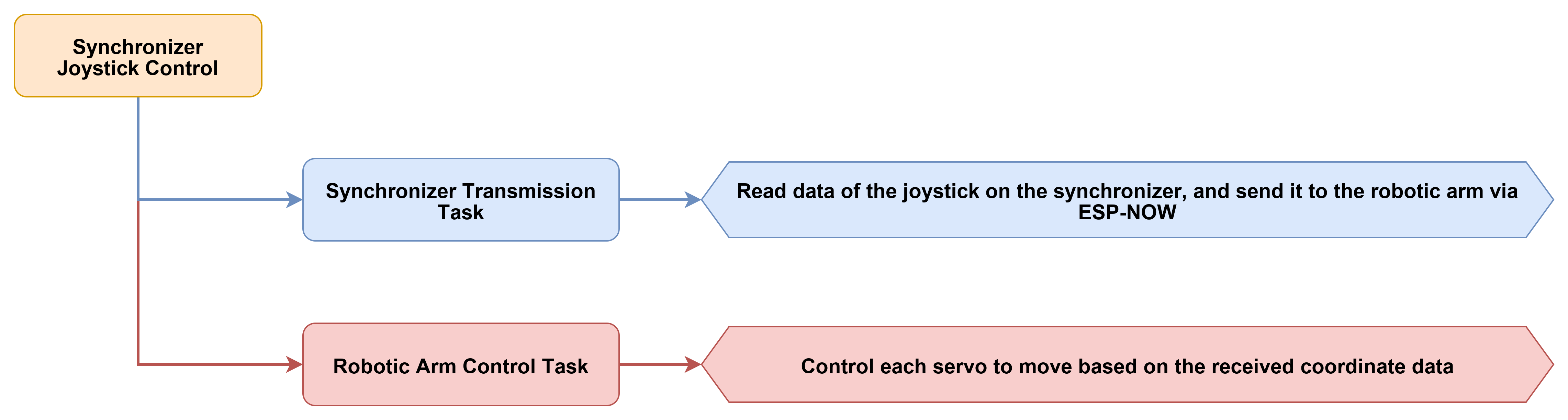
This section demonstrates how to control a robotic arm’s coordinates in real time via a dual-axis joystick on a synchronizer using an ESP-NOW wireless link. The synchronizer program reads the X and Y analog values of the joystick, maps them to the target X and Z coordinates of the robotic arm’s end-effector, and packages them into a CMD_COORDINATE_SET command for periodic transmission to the robotic arm. The robotic arm program receives this coordinate control command and transparently transmits it to the AT32 lower computer to execute inverse kinematics and interpolation motion, while concurrently displaying the current end-effector pose on the OLED.
7.9.2 Program Flow
7.9.3 Program Download
Robotic Arm Program Download
Locate the 02 Source Code folder in the same directory as this document, open the program file under Synchronizer Joystick Control\NexArm.zip\Nex_Arm, and download it to the robotic arm controller. For specific download steps, refer to 7.1 Program Download Instructions - Must Read.
Synchronizer Program Download
Locate the 02 Source Code folder in the same directory as this document, open the program file under Synchronizer Joystick Control\Synchronizer.zip\Nex_Arm, and download it to the synchronizer controller. For specific download steps, refer to 7.1 Program Download Instructions - Must Read.
7.9.4 Program Outcome
After the respective programs are downloaded to both ends, the devices enter the same ESP-NOW channel upon power-up. The synchronizer continuously reads the joystick position and transmits the corresponding target coordinates to the robotic arm via ESP-NOW. Upon receiving the coordinate control frame, the robotic arm drives the end-effector to move within the X and Z plane following the direction of the joystick. Meanwhile, the synchronizer serial port outputs the current target coordinates, and the robotic arm OLED displays the current end-effector pose in real time.
7.9.5 Program Analysis
Robotic Arm Analysis
The robotic arm program initially defines the runtime states required for ESP-NOW control reception, which include the current channel, global acceleration, synchronization mode switch, OLED refresh interval, battery refresh interval, and current pose cache. Consequently, upon receiving a coordinate control command, the program can both forward it to the underlying system for execution and synchronously update the local display state.
CommProtocol_t at32_protocol;
Preferences prefs;

uint8_t global_channel = DEFAULT_ESPNOW_CHANNEL;
uint8_t global_acc = 245;
bool espnow_sync_enabled = false;

uint32_t last_oled_refresh_ms = 0;
uint32_t last_bat_refresh_ms = 0;
uint32_t button_enable_ms = 0;
The function
func_ctrl_callback()serves as the core entry point for processing ESP-NOW protocol data on the robotic arm. Upon receivingCMD_COORDINATE_SET, the program first transparently transmits the command to the AT32 and then updates theX,Y,Z,Pitch,Roll, andClawparameters withinarm.current_poseto facilitate synchronous display on the OLED.
case CMD_COORDINATE_SET:
    servo.tx_frame_write(0xFF, self->elements.cmd, self->elements.args, payload_len);
    update_pose_from_coordinate_set(self->elements.args, payload_len);
    break;
The function
update_pose_from_coordinate_set()handles unpacking the received 14-byte coordinate parameters into specific pose values. Following the protocol sequence,Pitch,X,Y,Z,Roll, andClaware read sequentially, and the parsed results are written intoarm.current_pose. Consequently, the content displayed on the OLED remains consistent with the most recently received coordinate control command.
void update_pose_from_coordinate_set(const uint8_t* args, uint8_t payload_len)
{
    int16_t p_raw = (int16_t)((args[1] << 8) | args[0]);
    int16_t x_raw = (int16_t)((args[3] << 8) | args[2]);
    int16_t y_raw = (int16_t)((args[5] << 8) | args[4]);
    int16_t z_raw = (int16_t)((args[7] << 8) | args[6]);

    arm.current_pose.x = (float)x_raw;
    arm.current_pose.y = (float)y_raw;
    arm.current_pose.z = (float)z_raw;
    arm.current_pose.pitch = (float)p_raw / 10.0f;
}
The main loop first processes pending synchronization frames and AT32 response packets, followed by the periodic refresh of the buttons, battery, and OLED. Although this section primarily demonstrates joystick coordinate control, the robotic arm program retains the complete baseline refresh chain. Consequently, the interface and status displays are stably maintained during control reception.
void system_loop_handler(void)
{
    if (espnow_sync_enabled) {
        espnow_ctrl.processPendingSyncFrame(0);
    }

    pump_at32_feedback();
    arm.board.button.update();
    arm.board.buzzer.update();
    arm.board.bat.update();
}
The OLED refresh routine displays the six end-effector pose metrics—
X,Y,Z,Pitch,Roll, andClaw—at fixed intervals. Consequently, during joystick manipulation, the correspondence between end-effector coordinate variations and control commands can be observed directly, facilitating verification of wireless control efficacy.
if (now - last_oled_refresh_ms >= OLED_REFRESH_INTERVAL_MS) {
    last_oled_refresh_ms = now;
    arm.board.oled.show_status(
        arm.current_pose.x,
        arm.current_pose.y,
        arm.current_pose.z,
        arm.current_pose.pitch,
        arm.current_pose.roll,
        arm.current_pose.claw
    );
}
Synchronizer Analysis
The synchronizer program initially defines the core variables required for joystick control, including the broadcast target MAC address, transmission interval, current target coordinates, joystick center value, and debug output interval. These variables determine the transmission frequency, coordinate range, and joystick calibration results.
uint8_t broadcastMac[] = {0xFF, 0xFF, 0xFF, 0xFF, 0xFF, 0xFF};
unsigned long lastSendTime = 0;
unsigned long lastDebugTime = 0;

float current_x = 200.0f;
float current_y = 0.0f;
float current_z = 200.0f;
int joy_center_x = 2048;
int joy_center_y = 2048;
The function
calibrateJoystickCenter()reads the joystick analog values 20 times at startup to calculate an average, thereby determining the true center point of the joystick. This process mitigates drift issues caused by joystick zero-point deviations, ensuring the joystick remains near the center coordinates more reliably upon release.
void calibrateJoystickCenter() {
    long sumX = 0;
    long sumY = 0;
    for (int i = 0; i < 20; i++) {
        sumX += analogRead(JOYSTICK_X_PIN);
        sumY += analogRead(JOYSTICK_Y_PIN);
        delay(2);
    }
    joy_center_x = sumX / 20;
    joy_center_y = sumY / 20;
}
The initialization phase first configures the joystick pins, followed by completing ESP-NOW initialization, setting the channel, and adding the broadcast peer. Since a broadcast address is utilized, coordinate control packets transmitted by the joystick synchronizer can be directly received by the target robotic arm within the same channel, eliminating the need to hardcode a specific MAC address for the peer in advance.
WiFi.mode(WIFI_STA);
WiFi.disconnect();

esp_wifi_set_promiscuous(true);
esp_wifi_set_channel(WIFI_CHANNEL, WIFI_SECOND_CHAN_NONE);
esp_wifi_set_promiscuous(false);

esp_now_peer_info_t peerInfo = {};
memcpy(peerInfo.peer_addr, broadcastMac, 6);
peerInfo.channel = WIFI_CHANNEL;
peerInfo.encrypt = false;
esp_now_add_peer(&peerInfo);
Within the main loop, the X and Y analog values of the joystick are read every
SEND_INTERVAL_MSand mapped to the targetXandZcoordinates of the robotic arm based on the center value and deadband range. TheYcoordinate remains fixed at0, meaning the joystick controls a movement process within a two-dimensional plane.
if (abs(joyY - joy_center_y) < 100) {
    joyY = joy_center_y;
}
if (joyY <= joy_center_y) {
    current_x = map(joyY, 0, joy_center_y, 400, 200);
} else {
    current_x = map(joyY, joy_center_y, 4095, 200, 400);
}
Upon completion of the joystick coordinate calculations, the program sequentially packages
Pitch,X,Y,Z,Roll,Claw, andTimeinto aCMD_COORDINATE_SETcoordinate control frame. After computing the checksum, it broadcasts the frame viaesp_now_send(). Consequently, the robotic arm receives a coordinate control command formatted according to the standard serial protocol.
packet[0] = 0xFF;
packet[1] = 0xFF;
packet[2] = 0xFF;
packet[3] = 0x10;
packet[4] = 0x08;

packet[7]  = x & 0xFF;
packet[8]  = (x >> 8) & 0xFF;
packet[11] = z & 0xFF;
packet[12] = (z >> 8) & 0xFF;

esp_now_send(broadcastMac, packet, sizeof(packet));
The synchronizer retains serial debugging output to print the current target
X,Y, andZcoordinates at regular intervals. Through this printed data, the correspondence between joystick movements and transmitted coordinates can be directly observed, facilitating evaluation of whether the control direction, deadband range, and coordinate mapping intervals are properly configured.
if (currentMillis - lastDebugTime > 200) {
    lastDebugTime = currentMillis;
    Serial.printf("Joy: X=%.1f Y=%.1f Z=%.1f\n", current_x, current_y, current_z);
}