3. Motion Control
3.1 Forward Kinematics Introduction
Forward kinematics describes how the end-effector pose is determined when the joint angles are known. In robotic arm control, forward kinematics is mainly used for current position recovery, pose verification, and target error analysis. For the main chain of this robotic arm, the core of forward kinematics is to first solve for the horizontal extension and vertical height within the side-view working plane, and then map these values back to the three-dimensional space using the base rotation angle.
3.1.1 Model Definition
All derivations of forward kinematics are established on a unified geometric model and angle reference system. Without defining the link lengths, offset directions, and angle reference edges beforehand, subsequent component decomposition, vector superposition, and pose simultaneous equations will lack a unified standard. The link parameters are defined as follows:
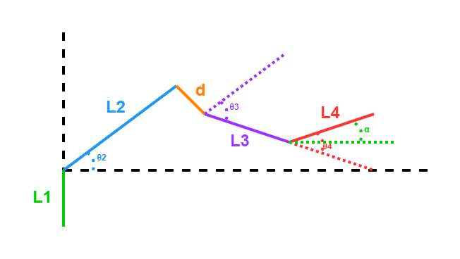
\(L_1\): The vertical height from the base to the shoulder joint
\(L_2\): The primary length of the second link
\(d\): The structural offset of the end of the second link
\(L_3\): The length of the third link
\(L_4\): The length of the end link
Geometrically, this main chain can be described as a vertical support \(L_1\) between the base and the shoulder joint, followed by a structure composed of the main link \(L_2\) and the end offset \(d\). The offset endpoint then connects to the third link \(L_3\), and finally to the end link \(L_4\). Therefore, this mechanical structure is not an ideal standard three-link mechanism, but a serial mechanism with an offset.
Regarding angle definitions, \(\theta_2\) represents the angle of \(L_2\) relative to the horizontal reference line. The angle \(\theta_3\) represents the angle from a reference line parallel to \(L_2\) to the link \(L_3\) at the offset endpoint. The angle \(\theta_4\) represents the angle from the extension direction of \(L_3\) to \(L_4\). The angle \(\alpha\) represents the absolute directional angle of the end link \(L_4\) relative to the horizontal reference line.
Based on these definitions, the directional relationships of each link are represented as: $\( \mathrm{dir}(L_2)=\theta_2 \)$
It is important to note that \(\theta_3\) is a local angle or a relative angle. It is not the absolute directional angle of the third link relative to the horizontal reference line because the absolute direction must be obtained through step-by-step accumulation.
3.1.2 Pose Relationship
In the main chain, the end-effector pose is not determined by a single joint, but is the result of the joint action of the shoulder, elbow, and wrist joints. Writing out the pose relationship first allows for the subsequent distinction of which angles are responsible for position solving and pose compensation. When the end-effector pose \(\alpha\) is known, \(\theta_4\) is no longer an independent variable, but is jointly determined by \(\theta_2\) and \(\theta_3\).
The end-effector pose satisfies:
Solving these simultaneous equations yields the wrist compensation angle:
3.1.3 Working Plane Vector Decomposition
The end-effector position of the robotic arm is essentially the superposition of multiple link displacements. To express this superposition process as a calculable formula, each link segment must first be decomposed into the horizontal and vertical axes according to its absolute directional angle.
Within the working plane, the end-effector position can be regarded as the algebraic sum of several vectors. Each link is first decomposed into the horizontal and vertical axes according to its absolute directional angle, and then a step-by-step superposition is performed.
The primary direction vector of the second link is represented as:
The offset vector is represented as:
The third link vector is represented as:
The fourth link vector is represented as:
In these vectors, the third link and the fourth link use absolute directional angles, resulting in the terms \(\theta_2+\theta_3\) and \(\theta_2+\theta_3+\theta_4\), respectively.
3.1.4 Total Displacement in the Working Plane
Listing the vector of each link individually only explains local geometric relationships. The overall position expression of the end-effector in the working plane, which is the displacement result required by forward kinematics, is obtained only after adding all terms together.
Let the horizontal extension in the side-view plane be length, and the vertical height be \(height\).
Simplifying these equations yields:
These equations provide the position solution in the side-view working plane. The offset amount \(d\) appears only in the second stage of the structure, but it simultaneously affects both the horizontal and vertical components.
3.1.5 Spatial Mapping
The aforementioned derivations are based on the side-view working plane, whereas the robotic arm actually operates in three-dimensional space. To obtain the real spatial coordinates of the end-effector, the results from the working plane must be mapped to the three-dimensional coordinate system.
Specifically, the horizontal extension in the working plane is projected onto the spatial coordinate system through the base rotation angle \(\theta_1\) to obtain the positions in the \(x\) and \(y\) directions. The height component in the plane directly corresponds to the \(z\) direction in the spatial coordinates. The spatial coordinates are expressed as: $\( x = length \cos(-\theta_1) \)$
Therefore, the forward kinematics of the robotic arm can be divided into two steps. First, solve for the horizontal extension and height of the end-effector within the two-dimensional working plane. Then, complete the three-dimensional spatial mapping through the base rotation angle. Forward kinematics eventually establishes the following mapping relationship:
3.2 Inverse Kinematics Introduction
The goal of inverse kinematics is to calculate joint angles from the end-effector pose. In simple terms, it calculates the rotation angle required for each joint based on the known coordinates of the robotic arm end-effector:
Compared with forward kinematics, inverse kinematics does not superimpose step-by-step forward. Instead, it reverses the geometric relationships of each stage from the end target, relying more on auxiliary construction and simultaneous angles. The main difficulties of inverse kinematics stem from three aspects:
The end target is represented by spatial coordinates while joint variables are angles, meaning they belong to different description spaces.
The end-effector pose \(\alpha\) simultaneously constrains \(\theta_2\), \(\theta_3\), and \(\theta_4\).
The structural offset \(d\) in the second stage makes the actual mechanical structure deviate from a standard two-link mechanism.
Therefore, the inverse kinematics cannot directly output all joint angles at once. Instead, it must go through several stages including coordinate dimension reduction, wrist point backward derivation, equivalent link representation, triangle constraints, and angle recovery, to gradually transform the spatial target into real joint solutions.
3.2.1 Coordinate Dimension Reduction
Base rotation and main chain extension belong to two different categories of motion geometrically. Without decomposing the three-dimensional problem first, the base orientation and the planar link relationship will be coupled, making it difficult to directly apply planar geometry tools afterwards.
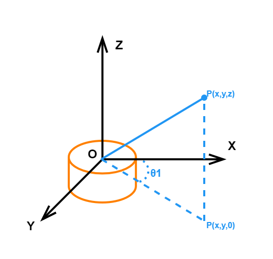
The inverse solution first projects the target point onto the working plane. Let the projection radius of the target point in the horizontal plane be:
The base angle is calculated as:
In this manner, the three-dimensional problem is decomposed into the base rotation angle \(\theta_1\) and the remaining three angles in the side-view working plane.
Performing spatial dimension reduction first is necessary because base rotation only affects the orientation of the target point in the horizontal plane without changing the length relationships of the main chain in the side-view plane. Calculating \(\theta_1\) independently simplifies the remaining calculations into a geometric problem within a two-dimensional plane.
Decompose the three-dimensional coupling problem into two parts: planar orientation and planar links.
Enable direct application of wrist point backward derivation, the law of cosines, and inverse trigonometric functions.
Avoid handling base rotation and main chain extension simultaneously in three-dimensional space.
3.2.2 Wrist Point Backward Derivation
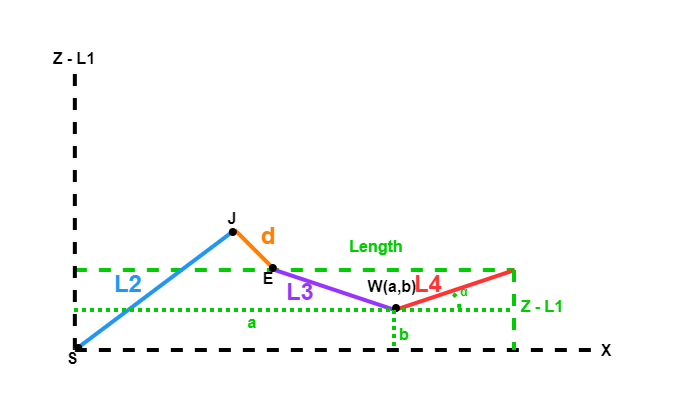
When the end-effector pose \(\alpha\) is known, the direction of the fourth link \(L_4\) is already determined. Isolating \(L_4\) from the assembly converts the objective from reaching the target at the end-effector point to reaching the target at the wrist point. This reduction eliminates one link from the direct geometric calculations. Since the end-effector pose \(\alpha\) is known, the direction of the fourth link \(L_4\) is also determined. Therefore, the end-effector point can be projected backward along the opposite direction of \(L_4\) to obtain the wrist point with coordinates \((a,b)\):
Consequently, the main problem of the inverse solution is converted from the end-effector point reaching the target to the front-stage main chain composed of \(L_2\), the offset \(d\), and \(L_3\) delivering the wrist point to the target position.
3.2.3 Equivalent Link
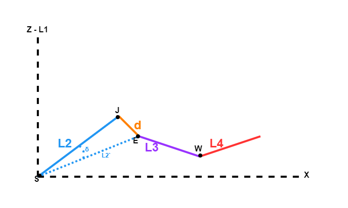
The path from the shoulder joint to the wrist point is not a standard single second link, but a physical mechanical structure combined from the primary length \(L_2\), the structural offset \(d\), and the third link. Without performing equivalent link treatment first, the solving method for a standard two-dimensional two-link mechanism cannot be directly applied. Because the second stage has a structural offset \(d\), the physical mechanical structure between the shoulder joint and the wrist point is not a standard two-link mechanism, requiring equivalent simplification first. Let the equivalent second link length be \(L_2'\) and the correction angle be \(\delta\). The actual mechanical structure between the shoulder joint and the wrist point is represented as:
Where:
\(S \rightarrow J\) corresponds to the primary length \(L_2\)
\(J \rightarrow E\) corresponds to the structural offset \(d\)
\(E \rightarrow W\) corresponds to the third link \(L_3\)
Due to the additional offset \(d\) in the middle, this mechanical structure cannot be directly treated as a standard two-link mechanism from the shoulder joint to the elbow joint and then to the wrist point.
After this step, the complex mechanical structure from the shoulder joint to the offset endpoint can be represented by the equivalent link \(L_2'\) and the correction angle \(\delta\). This then forms a standard two-dimensional two-link triangle with the third link \(L_3\).
3.2.4 Triangle Constraint
Once the mechanical structure is equated to \(L_2'\) and \(L_3\), the inverse kinematics can be transformed into a standard triangle problem. Only after establishing this triangle do the law of cosines and inverse trigonometric functions have a clear geometric reference. Let the distance from the shoulder joint to the wrist point be:
A standard triangle with side lengths \(L_2'\), \(L_3\), and \(D\) is obtained. All subsequent angle recoveries are established on this triangle. Let the equivalent elbow angle be \(\gamma\). According to the law of cosines, the equation is written as follows:
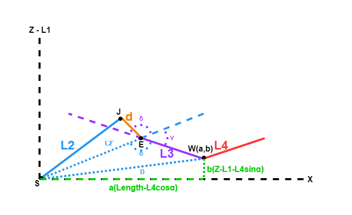
The angle \(\gamma\) obtained here is the elbow geometric angle in the equivalent mechanism rather than the final physical elbow joint angle. The equivalent mechanism refers to the simplified solution model composed of \(L_2'\) and \(L_3\). This model is only used to establish triangle constraints for applying the law of cosines, meaning a physical \(L_2'\) link does not actually exist in the robotic arm.
3.2.5 Angle Recovery
Because the angles \(\beta\), \(\phi\), \(\gamma\), and \(\delta\) obtained through the triangle constraint are still auxiliary geometric quantities, they describe the directional relationships in the equivalent model rather than the actual joint angles to be executed by the servos. Therefore, these intermediate quantities must be remapped to \(\theta_2\), \(\theta_3\), and \(\theta_4\).
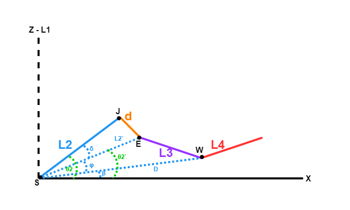
Let the directional angle from the shoulder joint pointing to the wrist point be:
The auxiliary angle is represented as:
The absolute directional angle of the equivalent second link is calculated as:
Combining this with the correction angle relationship:
This yields the absolute angle:
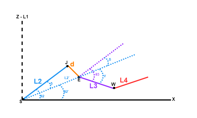
The absolute direction of the third link can be written as: $\( \theta_2 + \theta_3 \)$
It can also be written as:
Combining these two equations:
and
Simplifying these equations yields:
Up to this point, \(\beta\), \(\phi\), \(\gamma\), and \(\delta\) are still only auxiliary geometric quantities in the equivalent triangle and are not the actual joint angles required by the controller. Therefore, angle recovery must be performed to remap the angular relationships from the equivalent model back to the physical joint angles \(\theta_2\), \(\theta_3\), and \(\theta_4\) in the physical mechanical structure.
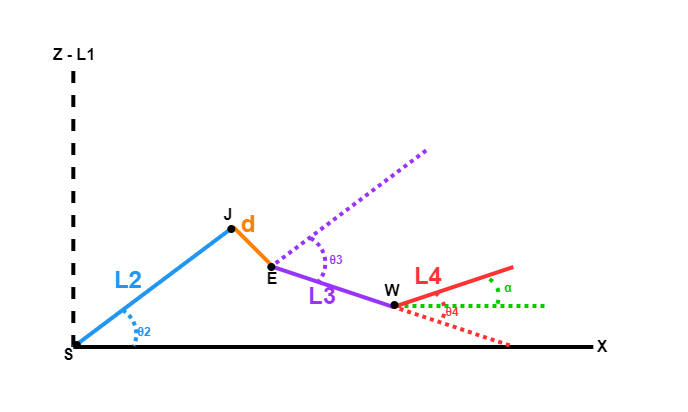
Finally, according to the pose constraint:
Solving these simultaneous equations yields:
Angle recovery is required because the law of cosines only directly provides the equivalent geometric relationships. In contrast, the physical robotic arm has the offset correction angle \(\delta\) and the end-effector pose constraint \(\alpha = \theta_2 + \theta_3 + \theta_4\). Only by combining these constraints can the joint angles in the physical mechanical structure be obtained from the geometric angles in the equivalent triangle to generate executable inverse solutions.
3.3 Serial Protocol Analysis
A serial protocol is a set of rules followed by devices during data exchange through serial communication. It typically specifies aspects such as data transmission format, data length, functional identification, parameter content, and checksum methods. Devices like microcontrollers, sensors, servo driver boards, and vision modules often use serial protocols to complete command transmission and data feedback.
3.3.1 Host-Device Communication Principle
This section introduces details regarding the host-device relationship of the NexArm when communicating with a PC host. It explains how the NexArm acts as a slave to communicate with other devices and how other devices act as hosts to control the NexArm. In the host-device control system, the NexArm acts as a slave device and transmits information with other devices through the UART serial port.
3.3.1.1 NexArm as the Device
Receive and parse signals transmitted from the host:
Wait for serial signals. If data is received on the serial port, parse the serial data according to the communication protocol to call the corresponding functions based on the data information.
Invoke NexArm functions according to the received data:
Once the signal is parsed, the corresponding functions of the NexArm device must be called. This includes retrieving the firmware version or controlling the buzzer.
Data packaging and feedback:
Upon receiving a read command, the corresponding read function is called. The retrieved data is then packaged into a data packet according to the communication protocol and sent to the host device.
3.3.1.2 External Systems as Hosts
Command packaging and transmission:
The host needs to package control commands and data into data packets according to the communication protocol and send them to the device.
Control coordination:
The host device must coordinate the collaborative operation of the entire system to ensure that communication and operations between the NexArm and other devices are conflict-free to maintain optimal working states.
Data reception:
When the host reads the robot status, it must receive the status data transmitted by the NexArm after sending a read command. This step ensures data integrity and correctness, followed by parsing the data packets to extract useful information.
3.3.2 Device Connection
Note
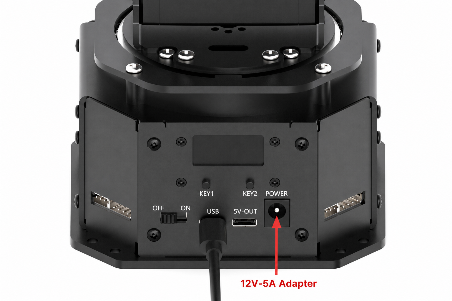
Before downloading the program, ensure that the serial driver has been installed.
Use a USB data cable to connect the host to the USB serial port on the NexArm controller.
3.3.3 Data Transmission Format
3.3.3.1 Serial Port Parameters
The default UART serial port data transmission configuration for the NexArm is as follows:
| Parameter | Value |
|---|---|
| Baud Rate | 1000000 |
| Data Bits | 8 |
| Parity Bit | None |
| Stop Bits | 1 |
3.3.3.2 Data Frame Format
When the NexArm communicates with host devices, a unified data frame format must be followed. Only by transmitting, receiving, and parsing data in accordance with the agreed protocol can both parties correctly identify and process the communication content. Any multi-byte integers, such as 16-bit or 32-bit integers, utilize little-endian byte order, placing the least significant byte first.
| Header 1 | Header 2 | Identifier | Data Length | Function Number | Parameter | Checksum |
|---|---|---|---|---|---|---|
| 0xFF | 0xFF | ID | Length | CMD | Parameter 1 ...Parameter N | Check |
Header: The reception of two consecutive
0xFFbytes indicates that a data packet has arrived.Identifier:
0xFFrepresents system commands processed by the control board. The range from0x01to0x06represents transparent transmission commands forwarded to specific servos.Data Length: Calculated as
2 + number of parameter bytes, which equals the sum of the CMD byte, parameter bytes, and checksum byte.Function Number: Used to indicate the purpose of an information frame.
Parameter: Represents the data information being transmitted.
Checksum: Calculated by accumulating bytes starting from the ID to the last parameter, taking the lower 8 bits, and then performing a bitwise NOT operation. The formula is
Sum = ~(ID + Len + CMD + ParameterN) & 0xFF.
3.3.5 Functional Command Analysis
3.3.5.1 Basic System Commands
Firmware Version Inquiry with function number 0x01: Used to retrieve the firmware version of the controller.
Data Sent by Host:
| Header 1 | Header 2 | Identifier | Data Length | Function Number | Parameter | Checksum |
|---|---|---|---|---|---|---|
| 0xFF | 0xFF | 0xFF | 0x02 | 0x01 | / | 0xFD |
Data Returned by Device:
| Header 1 | Header 2 | Identifier | Data Length | Function Number | Parameter | Checksum |
|---|---|---|---|---|---|---|
| 0xFF | 0xFF | 0xFF | 0x03 | 0x01 | Version number (3byte) | Check |
Example: Querying the firmware version. If the returned data is 01 00 00, it indicates version 1.0.0.
FF FF FF 02 01 FD
Battery Voltage Inquiry with function number 0x02: Used to retrieve power voltage data in mV.
Data Sent by Host:
| Header 1 | Header 2 | Identifier | Data Length | Function Number | Parameter | Checksum |
|---|---|---|---|---|---|---|
| 0xFF | 0xFF | 0xFF | 0x02 | 0x02 | / | 0xFC |
Data Returned by Slave:
| Header 1 | Header 2 | Identifier | Data Length | Function Number | Parameter | Checksum |
|---|---|---|---|---|---|---|
| 0xFF | 0xFF | 0xFF | 0x04 | 0x02 | Power voltage (2bytes) | Check |
Example: Querying the battery voltage. If the returned data is E0 1F, it represents 0x1FE0, which equals 8160mV in little-endian mode.
FF FF FF 02 02 FC
Buzzer Control with function number 0x09: Used to control the buzzer on-time, off-time, cycle count, and sounding frequency.
Data Sent by Host:
| Header 1 | Header 2 | Identifier | Data Length | Function Number | Parameter | Checksum |
|---|---|---|---|---|---|---|
| 0xFF | 0xFF | 0xFF | 0x0E | 0x09 | On-time(4bytes) + Off-time(4bytes) + Count (2bytes) + Frequency (2bytes) | Check |
Example: Controlling the buzzer to sound for 100ms, pause for 100ms, repeat for 2 cycles, at a frequency of 2000Hz.
FF FF FF 0E 09 64 00 00 00 64 00 00 00 02 00 D0 07 48
3.3.5.2 Coordinate and Kinematics Control Commands
Coordinate Setting with function number 0x08: Used to transmit the end-effector target coordinates and pose to the robotic arm. The inverse kinematics solution is completed by the underlying system.
Data Sent by Host:
| Header 1 | Header 2 | Identifier | Data Length | Function Number | Parameter | Checksum |
|---|---|---|---|---|---|---|
| 0xFF | 0xFF | 0xFF | 0x10 | 0x08 | Pitch(2bytes) + X(2bytes) + Y(2bytes) + Z(2bytes) + Roll(2bytes) + Claw(2bytes) + Time(2bytes) | Check |
The parameters are described as follows:
| Parameter Name | Type | Description |
|---|---|---|
| Pitch | int16 | The pitch angle of the end-effector in degrees |
| X | int16 | The X coordinate of the end-effector in mm |
| Y | int16 | The Y coordinate of the end-effector in mm |
| Z | int16 | The Z coordinate of the end-effector in mm |
| Roll | int16 | The roll angle of the end-effector in degrees |
| Claw | int16 | The target opening and closing angle of the gripper in degrees |
| Time | uint16 | The movement duration in ms |
Example: Controlling the robotic arm to move to the designated position in 1000ms, with parameters Pitch=0, X=200, Y=100, Z=200, Roll=0, Claw=0, and Time=1000ms.
FF FF FF 10 08 00 00 C8 00 64 00 C8 00 00 00 00 00 E8 03 09
Current Coordinate Inquiry with function number 0x0B: Used to retrieve the current coordinates of the robotic arm end-effector.
Data Sent by Host:
| Header 1 | Header 2 | Identifier | Data Length | Function Number | Parameter | Checksum |
|---|---|---|---|---|---|---|
| 0xFF | 0xFF | 0xFF | 0x02 | 0x0B | / | 0xF3 |
Data Returned by Device:
| Header 1 | Header 2 | Identifier | Data Length | Function Number | Parameter | Checksum |
|---|---|---|---|---|---|---|
| 0xFF | 0xFF | 0x5A | 0x08 | 0x0B | X(2bytes) + Y(2bytes) + Z(2bytes) | Check |
Example: Inquiring the current coordinates of the robotic arm.
FF FF FF 02 0B F3
Coordinate Increment Control with function number 0x32: Used to perform relative displacement control based on the current position of the robotic arm, with simultaneous control over the opening and closing increment of the gripper.
Data Sent by Host:
| Header 1 | Header 2 | Identifier | Data Length | Function Number | Parameter | Checksum |
|---|---|---|---|---|---|---|
| 0xFF | 0xFF | 0xFF | 0x10 | 0x32 | dX(2bytes) + dY(2bytes) + dZ(2bytes) + dPitch(2bytes) + dRoll(2bytes) + dClaw(2bytes) + Time(2bytes) | Check |
The parameters are described as follows:
| Parameter Name | Type | Description |
|---|---|---|
| dX | int16 | The increment along the X-axis in mm |
| dY | int16 | The increment along the Y-axis in mm |
| dZ | int16 | The increment along the Z-axis in mm |
| dPitch | int16 | The pitch angle increment in degrees multiplied by 10 |
| dRoll | int16 | The roll angle increment in degrees |
| dClaw | int16 | The gripper opening and closing angle increment in degrees |
| Time | uint16 | The movement duration in ms |
Example 1: Decreasing only the gripper angle by 20 degrees with a movement duration of 1000ms.
FF FF FF 10 32 00 00 00 00 00 00 00 00 00 00 EC FF E8 03 E8
Example 2: Increasing the X-axis by 10mm while opening the gripper by 10 degrees with a movement duration of 500ms.
FF FF FF 10 32 0A 00 00 00 00 00 00 00 00 00 F6 FF F4 01 CA
3.3.5.3 Wireless and System Configuration Commands
ESP-NOW Synchronization Mode Switch with function number 0x21: Used to control whether the robotic arm enters the real-time synchronization control mode. The mode must first be manually switched to ESP-NOW.
Data Sent by Host:
| Header 1 | Header 2 | Identifier | Data Length | Function Number | Parameter | Checksum |
|---|---|---|---|---|---|---|
| 0xFF | 0xFF | 0xFF | 0x03 | 0x21 | switch | Check |
The parameters are described as follows:
| Parameter Name | Type | Description |
|---|---|---|
| switch | uint8 | The synchronization control mode switch, where 0x00 disables and 0x01 enables it |
Example: Enabling the ESP-NOW synchronization mode.
FF FF FF 03 21 01 DB
Set Global Acceleration with function number 0x1F: Used to configure the global movement acceleration of the robotic arm.
Data Sent by Host:
| Header 1 | Header 2 | Identifier | Data Length | Function Number | Parameter | Checksum |
|---|---|---|---|---|---|---|
| 0xFF | 0xFF | 0xFF | 0x03 | 0x1F | accel(1byte) | Check |
The parameters are described as follows:
| Parameter Name | Type | Description |
|---|---|---|
| accel | uint8 | The global acceleration of the robotic arm with a range from 0 to 254 |
Example: Setting the global acceleration to 40.
FF FF FF 03 1F 28 B6
Set ESP-NOW Channel with function number 0x1E: Used to configure the wireless communication channel.
Data Sent by Host:
| Header 1 | Header 2 | Identifier | Data Length | Function Number | Parameter | Checksum |
|---|---|---|---|---|---|---|
| 0xFF | 0xFF | 0xFF | 0x03 | 0x1E | channel(1byte) | Check |
The parameters are described as follows:
| Parameter Name | Type | Description |
|---|---|---|
| channel | uint8 | The wireless communication channel number with a range from 1 to 13 |
Example: Setting the ESP-NOW channel to 6.
FF FF FF 03 1E 06 D9
3.3.5.4 Chassis and Peripheral Control Commands
Mecanum Wheel Control with function number 0x22: Used to control the forward, backward, lateral translation, and rotation speeds of the chassis.
Data Sent by Host:
| Header 1 | Header 2 | Identifier | Data Length | Function Number | Parameter | Checksum |
|---|---|---|---|---|---|---|
| 0xFF | 0xFF | 0xFF | 0x05 | 0x22 | Vx(1byte) + Vy(1byte) + Vz(1byte) | Check |
The parameters are described as follows:
| Parameter Name | Type | Description |
|---|---|---|
| Vx | int8 | The forward and backward speed with a range from -100 to 100 |
| Vy | int8 | The lateral translation speed with a range from -100 to 100 |
| Vz | int8 | The rotation speed with a range from -100 to 100 |
Example: Controlling the chassis to operate at a forward speed of 30, a lateral translation of 0, and a rotation of 0.
FF FF FF 05 22 1E 00 00 BB
Stepper Motor Control with function number 0x13: Used to control the stepper motor to execute a target number of steps.
Data Sent by Host:
| Header 1 | Header 2 | Identifier | Data Length | Function Number | Parameter | Checksum |
|---|---|---|---|---|---|---|
| 0xFF | 0xFF | 0xFF | 0x06 | 0x13 | step(4bytes) | Check |
The parameters are described as follows:
| Parameter Name | Type | Description |
|---|---|---|
| step | int32 | The target pulse count where the sign determines the direction |
Example: Controlling the stepper motor to run for 1000 steps.
FF FF FF 06 13 E8 03 00 00 FC
3.3.5.5 Single Servo Register Control
When the identifier ID is between 0x01 and 0x06, it indicates transparent transmission control is applied to the specified servo.
Servo Torque Control with write register 0x03 and register address 0x28: Used to control servo power status. Releasing the torque allows the servo to be rotated manually.
Data Sent by Host:
| Header 1 | Header 2 | Identifier | Data Length | Write Register | Register Address | Parameter | Checksum |
|---|---|---|---|---|---|---|---|
| 0xFF | 0xFF | ID | 0x04 | 0x03 | 0x28 | value(1byte) | Check |
The parameters are described as follows:
| Parameter Name | Type | Description |
|---|---|---|
| value | uint8 | The torque switch parameter where 0x00 represents release and 0x01 represents lock |
Example: Controlling servo 1 to enable torque.
FF FF 01 04 03 28 01 CE
Servo Acceleration Control with write register 0x03 and register address 0x29: Used to control servo acceleration to adjust the servo acceleration and deceleration profiles.
Data Sent by Host:
| Header 1 | Header 2 | Identifier | Data Length | Write Register | Register Address | Parameter | Checksum |
|---|---|---|---|---|---|---|---|
| 0xFF | 0xFF | ID | 0x04 | 0x03 | 0x29 | accel(1byte) | Check |
The parameters are described as follows:
| Parameter Name | Type | Description |
|---|---|---|
| accel | uint8 | The servo acceleration with an adjustment range from 0 to 254 |
Example: Controlling servo 1 to set the acceleration to 10.
FF FF 01 04 03 29 0A C4
Servo Position Control with write register 0x03 and register address 0x2A: Used to control the servo to rotate to a target position.
Data Sent by Host:
| Header 1 | Header 2 | Identifier | Data Length | Write Register | Register Address | Parameter | Checksum |
|---|---|---|---|---|---|---|---|
| 0xFF | 0xFF | ID | 0x05 | 0x03 | 0x2A | pos(2byte) | Check |
The parameters are described as follows:
| Parameter Name | Type | Description |
|---|---|---|
| pos | uint16 | The servo position parameter with a range from 0 to 4096 |
Example: Controlling servo 1 to rotate to position 2048.
FF FF 01 05 03 2A 00 08 C4
Servo Speed Control with write register 0x03 and register address 0x2E: Used to control the running steps during servo rotation.
Data Sent by Host:
| Header 1 | Header 2 | Identifier | Data Length | Write Register | Register Address | Parameter | Checksum |
|---|---|---|---|---|---|---|---|
| 0xFF | 0xFF | ID | 0x05 | 0x03 | 0x2E | spd(2byte) | Check |
The parameters are described as follows:
| Parameter Name | Type | Description |
|---|---|---|
| spd | uint16 | The number of steps executed per second with a range from 0 to 3400 |
Example: Controlling servo 1 to set the speed to 1000.
FF FF 01 05 03 2E E8 03 DD
Continuous Register Write Control with write register 0x03 and start address 0x29:
Data Sent by Host:
| Header 1 | Header 2 | Identifier | Data Length | Function Number | Parameter | Checksum |
|---|---|---|---|---|---|---|
| 0xFF | 0xFF | ID | 0x0A | 0x03 | ADDR(1byte) + ACC(1byte) + POS(2bytes) + RES(2bytes) + SPD(2bytes) | Check |
The parameters are described as follows:
| Parameter Name | Type | Description |
|---|---|---|
| ADDR | uint8 | The start register address which is fixed to 0x29 |
| ACC | uint8 | The servo acceleration with an adjustment range from 0 to 254 |
| POS | uint16 | The servo position parameter with a range from 0 to 4096 |
| RES | uint16 | The reserved bytes which must be filled with 0x00 spanning 2 bytes |
| SPD | uint16 | The number of steps executed per second with a range from 0 to 3400 |
Example: Controlling servo 1 to rotate to position 2048 with an acceleration of 0 and a speed of 0.
FF FF 01 0A 03 29 00 00 08 00 00 00 00 C0
3.3.5.6 Action Group Commands
Run Action Group with function number 0x03: The parameter represents the action group number.
Data Sent by Host:
| Header 1 | Header 2 | Identifier | Data Length | Function Number | Parameter | Checksum |
|---|---|---|---|---|---|---|
| 0xFF | 0xFF | 0xFF | 0x03 | 0x03 | actions(1byte) | Check |
The parameters are described as follows:
Parameter Name |
Type |
Description |
|---|---|---|
actions |
uint8 |
The action group number |
Example: Running action group 1.
FF FF FF 03 03 01 F9
Stop Action Group with function number 0x04: Used to interrupt the execution of action groups.
Data Sent by Host:
| Header 1 | Header 2 | Identifier | Data Length | Function Number | Parameter | Checksum |
|---|---|---|---|---|---|---|
| 0xFF | 0xFF | 0xFF | 0x02 | 0x04 | / | 0xFA |
Example: Stopping the current action group execution.
FF FF FF 02 04 FA
Erase Action Group with function number 0x17: Used to erase the action group with the specified number.
Data Sent by Host:
| Header 1 | Header 2 | Identifier | Data Length | Function Number | Parameter | Checksum |
|---|---|---|---|---|---|---|
| 0xFF | 0xFF | 0xFF | 0x03 | 0x17 | actions(1byte) | Check |
The parameters are described as follows:
Parameter Name |
Type |
Description |
|---|---|---|
actions |
uint8 |
The action group number |
Example: Erasing action group 1.
FF FF FF 03 17 01 E5
3.3.5.7 Checksum Calculation Example
Using the execution of action group 1 as an example, the checksum calculation method is as follows:
uint8_t id = 0xFF;
uint8_t len = 0x03;
uint8_t cmd = 0x03;
uint8_t arg0 = 0x01;

uint8_t checksum = ~(id + len + cmd + arg0) & 0xFF;
// The result is 0xF9
3.4 Program Download Must-Read
Before executing independent control functions, the corresponding control program must be downloaded to the robotic arm. Refer to the following steps for program download:
Connect the NexArm to the computer using a Type-C data cable.
Open the corresponding .ino program file in the 02 Source Code directory under the same path as this document.

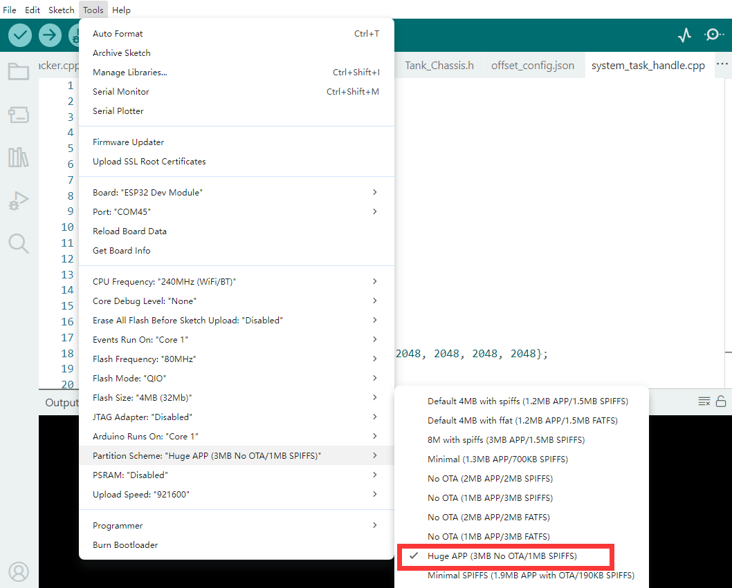
After opening the file, select the development board model. The specific model is shown in the image below:

Click Tools in the menu bar and select the corresponding ESP32 development board configuration according to the image below:
Click the compile button
 first, and then click the upload button
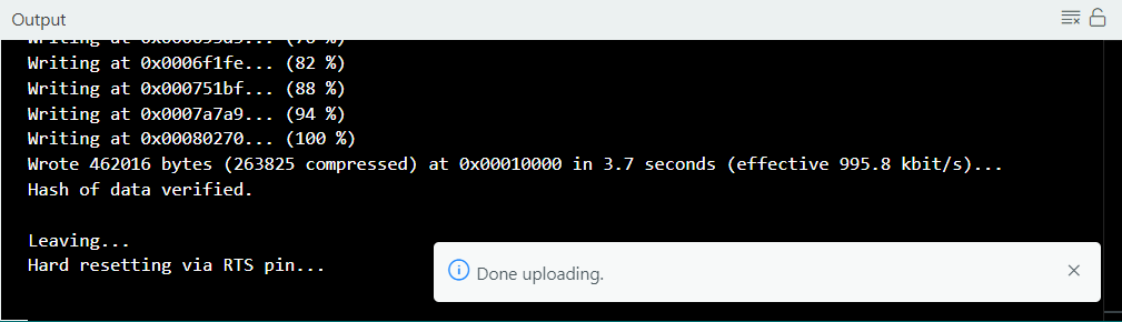
  . The output box at the bottom of the software, displaying the interface below, indicates that the program has been downloaded successfully:
3.5 Control Based on Forward and Inverse Kinematics
3.5.1 Project Introduction
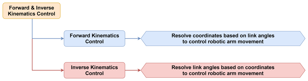
This section demonstrates the conversion relationship between the end-effector pose and the joint angles of the robotic arm by switching between inverse kinematics control mode and forward kinematics calculation mode using buttons. The program provides multiple sets of end-effector poses to directly drive the robotic arm movement. It also provides multiple sets of joint angle data to request forward kinematics calculation from the lower-level controller and subsequently control the movement of the robotic arm based on the calculation results.
3.5.2 Program Flow
3.5.3 Program Download
Locate the folder 02 Source Code in the same directory as this document, and find the program Control Based on Forward and Inverse Kinematics to download it. For specific download steps, refer to 3.4 Program Download Must-Read.
3.5.4 Program Outcome
After the robotic arm power-on initialization is completed, pressing the BOOT key switches the robotic arm movement between multiple sets of inverse kinematics target poses. Pressing the USER key causes the serial port to output the end-effector pose calculated by forward kinematics first. The robotic arm is then driven to the corresponding position according to this calculation result. The OLED screen displays the current end-effector pose information in real time to facilitate observation of the movement results.
3.5.5 Program Analysis
The main program first defines the protocol parsing object, the OLED refresh time, the battery refresh time, the status synchronization time, and the button enable time. It also defines the current inverse kinematics preset index, the current forward kinematics preset index, and the
fk_move_pendingflag.
CommProtocol_t at32_protocol;
uint32_t last_oled_refresh_ms = 0;
uint32_t last_bat_refresh_ms = 0;
uint32_t last_status_sync_ms = 0;
uint32_t button_enable_ms = 0;
uint8_t current_pose_index = 0;
uint8_t current_fk_index = 0;
bool fk_move_pending = false;
Subsequently, two sets of preset data are defined. The array
kDemoPoses[]stores the end-effector poses and movement durations. Pressing the BOOT key retrieves a target set from this array to perform inverse kinematics movement. The arraykDemoJoints[]stores the joint angles, therollparameter, and theclawparameter. Pressing the USER key retrieves a set of joint angle data from this array to perform forward kinematics calculations.
const IkPose kDemoPoses[] = {
    {200.0f, 0.0f, 200.0f, 0.0f, 0.0f, 0.0f, 1200},
    {220.0f, 80.0f, 180.0f, -10.0f, 0.0f, 15.0f, 1200},
};
In the initialization phase, the debugging serial port, the bus servo serial port, and the robotic arm object are initialized first. Then the servo torque is enabled and the robotic arm is returned to the initial position. Subsequently, the protocol parser is started and the callback function is registered.
void register_system_task(esp_event_loop_handle_t *event_loop)
{
    (void)event_loop;

    setCpuFrequencyMhz(240);
    Serial.begin(115200);

    servo.begin(Serial1, 1000000, 16, 17);
    arm.begin();
    arm.set_torque(true);
    delay(1000);
    arm.reset_all(1500);

    at32_protocol.begin();
    at32_protocol.register_success_callback(at32_packet_callback);
}
The function
apply_demo_pose()sequences the inverse kinematics data into a complete action. The function first retrieves the current pose fromkDemoPoses[]based on the index. Then it prints the coordinates, pose, gripper angle, and duration to the serial port. Finally it callsarm.move()to send the target pose to the lower-level controller for execution. Therefore, pressing the BOOT key initiates a clear process consisting of retrieving the current target, printing parameters, and executing movement.
void apply_demo_pose(uint8_t index)
{
    const IkPose& pose = kDemoPoses[index % (sizeof(kDemoPoses) / sizeof(kDemoPoses[0]))];
    Serial.printf(
        "[IK] target pose index %u -> x=%.1f y=%.1f z=%.1f pitch=%.1f roll=%.1f claw=%.1f time=%u\n",
        index,
        pose.x, pose.y, pose.z, pose.pitch, pose.roll, pose.claw, pose.duration_ms
    );
    arm.move(pose.x, pose.y, pose.z, pose.pitch, pose.roll, pose.claw, pose.duration_ms);
}
The function
request_fk_demo()corresponds to forward kinematics. It first retrieves the current joint angle data fromkDemoJoints[]and saves it tolast_requested_fk. Then it setsfk_move_pendingtotrueto indicate that once the forward kinematics result is received, a physical movement will be executed based on the result. Finally the function callsarm.request_fk_calc()to send the joint angles to the lower-level controller for forward kinematics calculation.
void request_fk_demo(uint8_t index)
{
    const FkJoints& joints = kDemoJoints[index % (sizeof(kDemoJoints) / sizeof(kDemoJoints[0]))];
    last_requested_fk = joints;
    fk_move_pending = true;
    arm.request_fk_calc(joints.j1, joints.j2, joints.j3, joints.j4, joints.roll, joints.claw);
}
After sending the request, the next key step is data packet parsing. The function
parse_pose_from_packet()decomposes the raw bytes in the AT32 returned packet intox,y,z,pitch,roll, andclaw. The functionupdate_pose_from_packet()synchronizes these values toarm.current_poseand extracts the positions of the 6 servos from theCMD_GET_CUR_COORDSpacket. In this way, both the serial output and the OLED refresh obtain the latest pose that has just been parsed.
void update_pose_from_packet(PacketTypeDef* rx_packet)
{
    parse_pose_from_packet(rx_packet, arm.current_pose);

    if (rx_packet->elements.cmd == CMD_GET_CUR_COORDS && rx_packet->elements.length >= 26) {
        for (int i = 0; i < 6; ++i) {
            int idx = 12 + i * 2;
            last_servo_positions[i] = (int16_t)((rx_packet->elements.args[idx + 1] << 8) | rx_packet->elements.args[idx]);
        }
        last_servo_feedback_ms = millis();
    }
}
In the
at32_packet_callback()function, when receivingCMD_GET_CUR_COORDSorCMD_IKINE_RESULT_GET, the function updates the current pose first. When receivingCMD_FKINE_RESULT_GET, it first parses the end-effector pose calculated by forward kinematics and checks whetherfk_move_pendingis set. If it is set, it immediately callsarm.move()to perform a physical movement based on the calculation result.
case CMD_FKINE_RESULT_GET:
{
    ArmPose_t fk_pose = {};
    parse_pose_from_packet(rx_packet, fk_pose);

    if (fk_move_pending) {
        fk_move_pending = false;
        arm.move(fk_pose.x, fk_pose.y, fk_pose.z, fk_pose.pitch, fk_pose.roll, fk_pose.claw, 1200);
    }
    break;
}
In the final loop, serial bytes are continuously fed into the protocol parser while the button, buzzer, battery, current status, and OLED are refreshed. When a click on the BOOT key is detected,
apply_demo_pose()is called. When a click on the USER key is detected,request_fk_demo()is called.
if (now >= button_enable_ms && arm.board.button.is_clicked(0)) {
    apply_demo_pose(current_pose_index);
}

if (now >= button_enable_ms && arm.board.button.is_clicked(1)) {
    request_fk_demo(current_fk_index);
}

if (now - last_status_sync_ms >= STATUS_SYNC_INTERVAL_MS) {
    last_status_sync_ms = now;
    arm.update_status();
}

if (now - last_oled_refresh_ms >= OLED_REFRESH_INTERVAL_MS) {
    last_oled_refresh_ms = now;
    arm.board.oled.show_status(
        arm.current_pose.x,
        arm.current_pose.y,
        arm.current_pose.z,
        arm.current_pose.pitch,
        arm.current_pose.roll,
        arm.current_pose.claw
    );
}
3.6 Coordinates and Servo Reading Based on Forward and Inverse Kinematics
3.6.1 Project Introduction
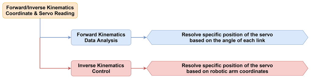
This section reads the calculation results of inverse kinematics and forward kinematics using buttons. It simultaneously outputs position data for the 6 servos. This approach is suitable for verifying the correctness of kinematics calculations without physically driving the movement of the robotic arm.
3.6.2 Program Flow
3.6.3 Program Download
Locate the folder 02 Source Code in the same directory as this document, find the program Coordinates and Servo Reading Based on Forward and Inverse Kinematics to download it. For specific download steps, refer to 3.4 Program Download Must-Read.
3.6.4 Program Outcome
After the robotic arm is powered on, pressing the BOOT key causes the serial port to output the end-effector pose and the 6 servo values calculated by inverse kinematics. Pressing the USER key causes the serial port to output the pose and the corresponding servo values calculated by forward kinematics. The OLED screen continuously displays the current end-effector pose.
3.6.5 Program Analysis
The main program first defines the protocol parsing object, the OLED refresh time, the battery refresh time, the button enable time, and the last servo feedback time. It also defines the current inverse kinematics reading index and the forward kinematics reading index. These variables do not directly control the movement of the robotic arm. Instead, they control when reading is allowed, which preset data set is currently being read, and how often the interface is refreshed.
CommProtocol_t at32_protocol;
uint32_t last_oled_refresh_ms = 0;
uint32_t last_bat_refresh_ms = 0;
uint32_t button_enable_ms = 0;
uint32_t last_servo_feedback_ms = 0;
uint8_t current_ik_index = 0;
uint8_t current_fk_index = 0;
The array
kIkReadTargets[]is used to store the end-effector pose data for inverse kinematics reading. The arraykFkReadTargets[]is used to store joint angle data for forward kinematics reading.
const IkPose kIkReadTargets[] = {
    {200.0f, 0.0f, 200.0f, 0.0f, 0.0f, 0.0f, 1200},
    {220.0f, 80.0f, 180.0f, -10.0f, 0.0f, 15.0f, 1200},
};
In the initialization function, the serial port, the bus servo serial port, the robotic arm object, and the protocol parser are initialized. Then the current status is synchronized once and any key clicks that might remain from the power-on stage are cleared. In this way, when the BOOT key or the USER key is pressed, both requests and returned packets can proceed in a clean state.
void register_system_task(esp_event_loop_handle_t *event_loop)
{
    (void)event_loop;

    setCpuFrequencyMhz(240);
    Serial.begin(115200);

    servo.begin(Serial1, 1000000, 16, 17);
    arm.begin();

    at32_protocol.begin();
    at32_protocol.register_success_callback(at32_packet_callback);
}
The function
request_ik_read()retrieves a set of end-effector poses fromkIkReadTargets[]and sends it to the lower-level controller usingarm.move()with the last parameter set totrue. The parametertrueindicates that the function performs calculations only without physical movement. The functionrequest_fk_read()delivers a set of joint angles toarm.request_fk_calc()and waits for the forward kinematics calculation result from the lower-level controller.
arm.move(pose.x, pose.y, pose.z, pose.pitch, pose.roll, pose.claw, pose.duration_ms, true);
After sending the request, the data in the returned packet needs to be extracted in two steps. The function
parse_pose_from_packet()reconstructs the byte stream intox,y,z,pitch,roll, andclaw. The functionparse_servo_positions_from_packet()extracts the 6 servo values from the latter half of the data. Finally,print_servo_positions()formats and prints these 6 values directly.
bool parse_servo_positions_from_packet(PacketTypeDef* rx_packet, int16_t servo_pos[6])
{
    if (rx_packet->elements.length < 26) {
        return false;
    }

    for (int i = 0; i < 6; ++i) {
        int idx = 12 + i * 2;
        servo_pos[i] = (int16_t)((rx_packet->elements.args[idx + 1] << 8) | rx_packet->elements.args[idx]);
    }
    return true;
}
Based on this parsing, the function
update_cached_feedback()saves the latest real-time feedback. The functionat32_packet_callback()processes returned packets based on the command type. The cache is updated when receiving theCMD_GET_CUR_COORDScommand. When receiving theCMD_IKINE_RESULT_GETorCMD_FKINE_RESULT_GETcommand, the function first parses the pose, then parses the servo values, and finally prints the combined results.
if (rx_packet->elements.cmd == CMD_FKINE_RESULT_GET) {
    ArmPose_t pose = {};
    int16_t servo_pos[6] = {0};
    parse_pose_from_packet(rx_packet, pose);
    parse_servo_positions_from_packet(rx_packet, servo_pos);
    arm.current_pose = pose;

    Serial.printf(
        "[FK] result -> x=%.1f y=%.1f z=%.1f pitch=%.1f roll=%.1f claw=%.1f\n",
        pose.x, pose.y, pose.z, pose.pitch, pose.roll, pose.claw
    );
    print_servo_positions(servo_pos);
}
In the final main loop, serial bytes are continuously fed into the parser, the button, buzzer, and battery status are updated, and the OLED is periodically refreshed. When a click on the BOOT key is detected, the program calls
request_ik_read()to initiate an inverse kinematics reading. When a click on the USER key is detected, it callsrequest_fk_read()to initiate a forward kinematics reading.
if (now >= button_enable_ms && arm.board.button.is_clicked(0)) {
    request_ik_read(current_ik_index);
}

if (now >= button_enable_ms && arm.board.button.is_clicked(1)) {
    request_fk_read(current_fk_index);
}

if (now - last_oled_refresh_ms >= OLED_REFRESH_INTERVAL_MS) {
    last_oled_refresh_ms = now;
    arm.board.oled.show_status(
        arm.current_pose.x,
        arm.current_pose.y,
        arm.current_pose.z,
        arm.current_pose.pitch,
        arm.current_pose.roll,
        arm.current_pose.claw
    );
}
3.7 Speed Planning
3.7.1 Project Introduction
This section demonstrates controlling the robotic arm using different accelerations and movement durations under identical or similar motion tasks. The program includes both single-stage speed planning and multi-stage speed planning to observe the movement differences of the robotic arm during the startup, rapid movement, and deceleration approach phases.
3.7.2 Program Flow

3.7.3 Program Download
Locate the folder 02 Source Code in the same directory as this document, find the program Speed Planning to download it. For specific download steps, refer to 3.4 Program Download Must-Read.
3.7.4 Program Outcome
The robotic arm synchronizes its status after power-on and does not move automatically by default. Pressing the BOOT key switches the robotic arm between the left and right target points, executing movement sequentially using three sets of speed planning parameters: gentle, balanced, and aggressive. The serial port outputs the current plan name, acceleration, duration, and target pose. Pressing the USER key causes the robotic arm to complete movement through four stages in sequence: depart, cruise, settle, and home. The serial port outputs the planning parameters and target pose for each stage, and the OLED screen continuously displays the current end-effector status.
3.7.5 Program Analysis
The main program first defines the state variables required during the execution of speed planning, including the protocol parsing object, the OLED refresh time, the battery refresh time, the status synchronization time, the button enable time, the last servo feedback time, the current speed planning index, and the left-right path switching flag.
CommProtocol_t at32_protocol;

uint32_t last_oled_refresh_ms = 0;
uint32_t last_bat_refresh_ms = 0;
uint32_t last_status_sync_ms = 0;
uint32_t button_enable_ms = 0;
uint32_t last_servo_feedback_ms = 0;

uint8_t current_speed_index = 0;
bool path_toggle = false;
The data used for speed planning is split into two layers. The structure
PoseTargetis used to store target poses. The structureSpeedPlanis used to store the plan name, movement acceleration, and duration. The variableskHomePose,kLeftPose,kRightPose,kApproachPose, andkSettlePosespecify the target poses corresponding to different stages. The arraykSpeedPlans[]provides three sets of parameters to be used cyclically for single-stage planning.
struct SpeedPlan {
    const char* name;
    uint8_t move_acc;
    uint16_t duration_ms;
};

const PoseTarget kHomePose = {200.0f, 0.0f, 200.0f, 0.0f, 0.0f, 0.0f};
const PoseTarget kLeftPose = {210.0f, 90.0f, 170.0f, -8.0f, 0.0f, 10.0f};
const PoseTarget kRightPose = {210.0f, -90.0f, 170.0f, -8.0f, 0.0f, 10.0f};

const SpeedPlan kSpeedPlans[] = {
    {"gentle", 10, 2800},
    {"balanced", 35, 1600},
    {"aggressive", 75, 850},
};
In the initialization phase, the serial port, the bus servo serial port, and the robotic arm object are initialized first. Then the protocol parser is started and the AT32 callback function is registered. Subsequently, the current status is synchronized once and any key clicks remaining from the power-on stage are cleared.
void register_system_task(esp_event_loop_handle_t *event_loop)
{
    (void)event_loop;

    setCpuFrequencyMhz(240);
    Serial.begin(115200);

    servo.begin(Serial1, 1000000, 16, 17);
    arm.begin();

    at32_protocol.begin();
    at32_protocol.register_success_callback(at32_packet_callback);

    sync_arm_feedback(300);
    arm.board.button.update();
    arm.board.button.is_clicked(0);
    arm.board.button.is_clicked(1);
    button_enable_ms = millis() + BUTTON_STARTUP_GUARD_MS;
}
The function
set_move_acc()provides the most critical control interface in speed planning. This function is defined inRobot_Arm.cpp. When called, the acceleration value is packaged into aCMD_SET_MOVE_ACCcommand and sent to the lower-level controller. Therefore, the main program does not only modify the movement duration when controlling speed, but also transmits the acceleration parameter simultaneously.
void Robot_Arm_t::set_move_acc(uint8_t acc)
{
    send_packet(CMD_SET_MOVE_ACC, &acc, 1);
}
The function
move_with_plan()first enables the torque. Then it callsarm.set_move_acc()to set the movement acceleration according to the currentSpeedPlan. Subsequently, the plan name, acceleration, duration, and target pose are printed to the serial port. Finally, the function callsarm.move()to execute the movement.
void move_with_plan(const PoseTarget& pose, const SpeedPlan& plan)
{
    arm.set_torque(true);
    arm.set_move_acc(plan.move_acc);
    Serial.printf(
        "[Speed] plan=%s acc=%u duration=%u -> x=%.1f y=%.1f z=%.1f pitch=%.1f roll=%.1f claw=%.1f\n",
        plan.name,
        plan.move_acc,
        plan.duration_ms,
        pose.x,
        pose.y,
        pose.z,
        pose.pitch,
        pose.roll,
        pose.claw
    );
    arm.move(pose.x, pose.y, pose.z, pose.pitch, pose.roll, pose.claw, plan.duration_ms);
}
The function
run_staged_speed_demo()internally defines three sets of stage parameters in sequence:depart,cruise, andsettle. Then it sequentially moves the robotic arm tokApproachPose,kRightPose,kSettlePose, andkHomePose. Each stage transition sets the corresponding acceleration before executing the target pose. As a result, the entire movement sequence clearly demonstrates the differences between starting up, rapid movement, and decelerating back to the position.
const SpeedPlan stage_depart = {"depart", 8, 2200};
const SpeedPlan stage_cruise = {"cruise", 70, 950};
const SpeedPlan stage_settle = {"settle", 18, 1700};

arm.set_move_acc(stage_depart.move_acc);
arm.move(kApproachPose.x, kApproachPose.y, kApproachPose.z, kApproachPose.pitch, kApproachPose.roll, kApproachPose.claw, stage_depart.duration_ms);

arm.set_move_acc(stage_cruise.move_acc);
arm.move(kRightPose.x, kRightPose.y, kRightPose.z, kRightPose.pitch, kRightPose.roll, kRightPose.claw, stage_cruise.duration_ms);
During the execution of speed planning, the pose updates are still completed through the AT32 returned packets. The function
parse_pose_from_packet()decomposes the returned packet bytes intox,y,z,pitch,roll, andclaw. The functionupdate_pose_from_packet()synchronizes the results toarm.current_poseand updates the feedback timestamp. In this way, regardless of the planning method currently being executed by the robotic arm, the OLED screen always displays the latest end-effector status.
void update_pose_from_packet(PacketTypeDef* rx_packet)
{
    parse_pose_from_packet(rx_packet, arm.current_pose);

    if (rx_packet->elements.cmd == CMD_GET_CUR_COORDS && rx_packet->elements.length >= 26) {
        for (int i = 0; i < 6; ++i) {
            int idx = 12 + i * 2;
            last_servo_positions[i] = (int16_t)((rx_packet->elements.args[idx + 1] << 8) | rx_packet->elements.args[idx]);
        }
        last_servo_feedback_ms = millis();
    }
}
In the main loop, parsing of AT32 returned packets, button updates, buzzer refresh, battery refresh, and OLED refresh are continuously processed. When a click on the BOOT key is detected, the main program retrieves the current planning parameters from
kSpeedPlans[]and callsmove_with_plan()alternately between the left and right target poses. When a click on the USER key is detected, it directly callsrun_staged_speed_demo()to run the entire multi-stage speed planning sequence.
if (now >= button_enable_ms && arm.board.button.is_clicked(0)) {
    const PoseTarget& target = path_toggle ? kLeftPose : kRightPose;
    const SpeedPlan& plan = kSpeedPlans[current_speed_index];
    move_with_plan(target, plan);

    current_speed_index = (current_speed_index + 1) % (sizeof(kSpeedPlans) / sizeof(kSpeedPlans[0]));
    path_toggle = !path_toggle;
}

if (now >= button_enable_ms && arm.board.button.is_clicked(1)) {
    run_staged_speed_demo();
}
3.8 Gripper Control
3.8.1 Project Introduction
This section maintains the robotic arm in a fixed standby pose and controls the opening and closing of the gripper by changing the claw parameter.
3.8.2 Program Flow

3.8.3 Program Download
Locate the folder 02 Source Code in the same directory as this document, find the program Gripper Control to download it. For specific download steps, refer to 3.4 Program Download Must-Read.
3.8.4 Program Outcome
After the robotic arm is powered on, pressing the BOOT key switches the gripper state. The serial port outputs the current gripper angle, acceleration, and duration. Simultaneously, the OLED screen continues to display the current end-effector status to facilitate observation of the gripper opening and closing process.
3.8.5 Program Analysis
The main program first uses
PoseTargetandGripperPresetto define two core categories of data separately.PoseTargetrepresents the spatial pose that remains constant during the gripper demonstration.GripperPresetdescribes the gripper preset name, the gripper angle, the movement acceleration, and the duration.
struct GripperPreset {
    const char* name;
    float claw;
    uint8_t move_acc;
    uint16_t duration_ms;
};

const PoseTarget kStandbyPose = {200.0f, 0.0f, 200.0f, 0.0f, 0.0f, 0.0f};
const GripperPreset kGripperPresets[] = {
    {"open", -50.0f, 16, 900},
    {"close", 15.0f, 16, 900},
};
The initialization phase mainly involves serial port initialization, bus servo serial port initialization, robotic arm object initialization, and protocol callback registration. Then the current status is synchronized once and any button status remaining from the early power-on stage is cleared.
void register_system_task(esp_event_loop_handle_t *event_loop)
{
    (void)event_loop;

    Serial.begin(115200);
    servo.begin(Serial1, 1000000, 16, 17);
    arm.begin();

    at32_protocol.begin();
    at32_protocol.register_success_callback(at32_packet_callback);
}
When executing a gripper movement,
move_to_pose_with_claw()is entered first. This function is responsible for sending the target pose and gripper angle to the lower-level controller for execution. It first enables the torque, then sets the movement acceleration, and finally callsarm.move()to execute the movement.
void move_to_pose_with_claw(const PoseTarget& pose, uint8_t move_acc, uint16_t duration_ms)
{
    arm.set_torque(true);
    arm.set_move_acc(move_acc);
    arm.move(pose.x, pose.y, pose.z, pose.pitch, pose.roll, pose.claw, duration_ms);
}
The function
apply_gripper_preset()connects the two steps of selecting a preset and executing the movement. The function writes theclawvalue from the current preset, prints the preset name, gripper angle, acceleration, duration, and current pose to the serial port, and finally callsmove_to_pose_with_claw().
void apply_gripper_preset(const GripperPreset& preset)
{
    PoseTarget target = kStandbyPose;
    target.claw = preset.claw;

    Serial.printf(
        "[Gripper] preset=%s claw=%.1f acc=%u duration=%u pose=(x=%.1f y=%.1f z=%.1f pitch=%.1f roll=%.1f)\n",
        preset.name,
        preset.claw,
        preset.move_acc,
        preset.duration_ms,
        target.x,
        target.y,
        target.z,
        target.pitch,
        target.roll
    );

    move_to_pose_with_claw(target, preset.move_acc, preset.duration_ms);
}
After the gripper action is executed, the pose updates are still completed through the AT32 returned packets. The function
parse_pose_from_packet()decomposes the raw bytes in the returned packet into pose fields, and thenupdate_pose_from_packet()synchronizes the parsing results toarm.current_pose.
void update_pose_from_packet(PacketTypeDef* rx_packet)
{
    parse_pose_from_packet(rx_packet, arm.current_pose);

    if (rx_packet->elements.cmd == CMD_GET_CUR_COORDS && rx_packet->elements.length >= 26) {
        last_servo_feedback_ms = millis();
    }
}
In the main loop, parsing of AT32 returned packets, button updates, and buzzer refresh are processed first, followed by updates to the battery, current status, and OLED according to time slices. When a click on the BOOT key is detected, the current preset is retrieved from
kGripperPresets[]to callapply_gripper_preset(), andcurrent_gripper_indexis incremented by one.
if (now >= button_enable_ms && arm.board.button.is_clicked(0)) {
    const GripperPreset& preset = kGripperPresets[current_gripper_index];
    apply_gripper_preset(preset);
    current_gripper_index = (current_gripper_index + 1) % (sizeof(kGripperPresets) / sizeof(kGripperPresets[0]));
}

if (now - last_oled_refresh_ms >= OLED_REFRESH_INTERVAL_MS) {
    last_oled_refresh_ms = now;
    arm.board.oled.show_status(
        arm.current_pose.x,
        arm.current_pose.y,
        arm.current_pose.z,
        arm.current_pose.pitch,
        arm.current_pose.roll,
        arm.current_pose.claw
    );
}
3.9 Fixed-Point Gripping and Transport
3.9.1 Project Introduction
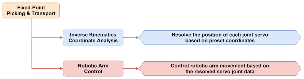
This section completes the fixed-point gripping and transporting tasks of the robotic arm using a preset sequence of fixed points and gripper actions.
3.9.2 Program Flow
3.9.3 Program Download
Locate the folder 02 Source Code in the same directory as this document, find the program Fixed-Point Gripping and Transport to download it. For specific download steps, refer to 3.4 Program Download Must-Read.
3.9.4 Program Outcome
After the robotic arm is powered on, pressing the BOOT key causes the robotic arm to execute gripping, transporting, placing, and returning movements sequentially according to the preset process. The serial port outputs the pose and duration for each step, and the OLED screen continuously displays the current end-effector status.
3.9.5 Program Analysis
The main program first abstracts each movement step into
PoseTarget. The structure uniformly savesx,y,z,pitch,roll,claw, andduration_ms, allowing all movement data to be described using a single data format.
struct PoseTarget {
    float x;
    float y;
    float z;
    float pitch;
    float roll;
    float claw;
    uint16_t duration_ms;
};
The array
kPickPlaceSequence[]organizes the movement process into a sequential list. Each element in the array represents a specific execution step. The first few items handle descending and closing the gripper, the middle items handle lifting and transporting, and the last few items handle descending, opening the gripper, and returning to the end position.
const PoseTarget kPickPlaceSequence[] = {
    {250.0f, 0.0f, 20.0f, -90.0f, 0.0f, -50.0f, 2000},
    {250.0f, 0.0f, 20.0f, -90.0f, 0.0f, 0.0f, 2000},
};
In the initialization function, the serial port, the bus servo serial port, and the robotic arm object are initialized first. Then the torque is enabled. After a delay for stabilization, the robotic arm is returned to the initial position. Finally, the protocol parser is started and the callback function is registered.
arm.begin();
arm.set_torque(true);
delay(1000);
arm.reset_all(1500);

at32_protocol.begin();
at32_protocol.register_success_callback(at32_packet_callback);
When executing each specific movement step, the program enters
run_pose_step(). This function first sets the torque and movement acceleration, then prints the current step number, target pose, gripper angle, and duration to the serial port. Finally, it callsarm.move()to send this step to the lower-level controller for execution. Thedelay()function at the end of the function is designed to allow the current action to finish before entering the next step to prevent overlapping between steps.
void run_pose_step(const PoseTarget& pose, uint8_t step_index)
{
    arm.set_torque(true);
    arm.set_move_acc(PICK_PLACE_MOVE_ACC);

    Serial.printf(
        "[PickPlace] step=%u x=%.1f y=%.1f z=%.1f pitch=%.1f roll=%.1f claw=%.1f time=%u\n",
        (unsigned int)step_index,
        pose.x,
        pose.y,
        pose.z,
        pose.pitch,
        pose.roll,
        pose.claw,
        pose.duration_ms
    );

    arm.move(pose.x, pose.y, pose.z, pose.pitch, pose.roll, pose.claw, pose.duration_ms);
    delay(pose.duration_ms + 150);
}
With the single-step execution function defined, the function
run_pick_place_sequence()is responsible for executing the entire array in sequence. Upon entry, the function prints starting information, then uses aforloop to retrieve each step inkPickPlaceSequence[]sequentially and deliver it torun_pose_step()for execution. Once all steps are completed, ending information is printed accompanied by a buzzer notification.
void run_pick_place_sequence()
{
    Serial.println("[PickPlace] sequence start");

    for (uint8_t i = 0; i < (sizeof(kPickPlaceSequence) / sizeof(kPickPlaceSequence[0])); ++i) {
        run_pose_step(kPickPlaceSequence[i], (uint8_t)(i + 1));
    }

    Serial.println("[PickPlace] sequence finished");
    arm.board.buzzer.set(60, 60, 2, 2200);
}
During execution, the pose feedback is still refreshed by the returned packets. The function
parse_pose_from_packet()decodes the raw bytes returned from the lower-level controller into the current end-effector pose. The functionupdate_pose_from_packet()synchronizes this result toarm.current_poseand updates the timestamp when receiving real-time coordinate returned packets.
void update_pose_from_packet(PacketTypeDef* rx_packet)
{
    parse_pose_from_packet(rx_packet, arm.current_pose);
    if (rx_packet->elements.cmd == CMD_GET_CUR_COORDS) {
        last_servo_feedback_ms = millis();
    }
}
In the main loop, parsing of AT32 returned packets, button updates, buzzer refresh, battery status refresh, and OLED display are continuously processed. When a click on the BOOT key is detected, the program calls
run_pick_place_sequence()to start the entire fixed-point gripping and transporting process.
if (now >= button_enable_ms && arm.board.button.is_clicked(0)) {
    run_pick_place_sequence();
}

if (now - last_oled_refresh_ms >= OLED_REFRESH_INTERVAL_MS) {
    last_oled_refresh_ms = now;
    arm.board.oled.show_status(
        arm.current_pose.x,
        arm.current_pose.y,
        arm.current_pose.z,
        arm.current_pose.pitch,
        arm.current_pose.roll,
        arm.current_pose.claw
    );
}